Unit - 2
Network theorems
Q1) Find the current through  resistance. Using superposition theorem?
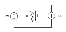
A1)
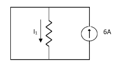
Fig. Short circuit 2V
 1= 0
1= 0

Fig. Open circuit 6A
 2=
2=
 1 +
1 +  2
2 
Q2) Find Value of current I using superposition theorem?
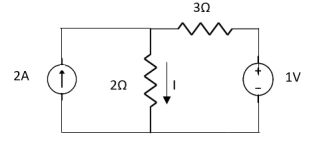
A2)
Applying Superposition Theorem
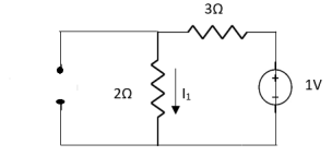
Fig. Circuit with 2A open circuit
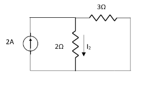
Fig. Circuit with 1V short circuit
 1 =
1 = 
 2 =
2 = 
=
 1 +
1 +  2
2
= 
Q3) Find Vth and Rth for the circuit shown below?

A3)
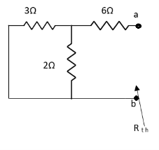
Fig. Circuit for finding Rth


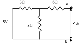
Fig. Finding Vth across a and b


Finding Isc from circuit directly:
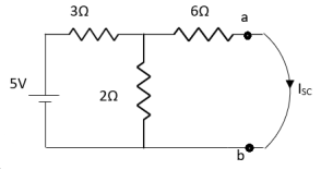
Fig. Finding Isc
By KCL,


Q4) Find Vth and ISC across a and b?
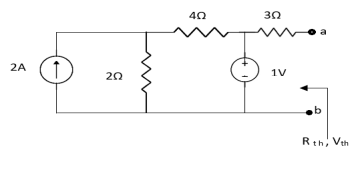
A4)
Finding Rth
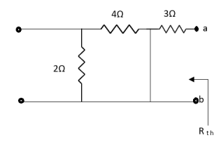
Fig. Circuit for Rth
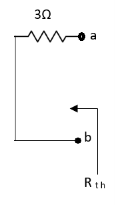
Also, clear from circuit that Vth = 1V.
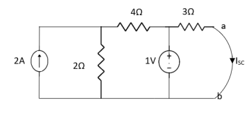
Fig. Circuit for Isc
By applying KVL we get,
1-3Isc=0
Isc= A
A
Q5) Find Isc and Rth across terminal a and b?
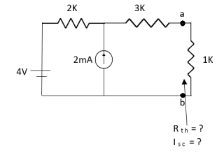
A5)
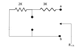
Fig. Circuit for finding RTh
Rth=3k+2k=5k
By applying KVL we get


Therefore, 
Q6) Find the value of voltage Vx?
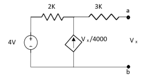
A6)
For Rth
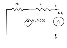
Fig. Circuit for finding Rth
By KCL,


But, 


By KVL,


Q7) Find value of current I in the circuit?
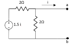
A7)
Since, no independent source is present so,
Isc = 0
And we know that,


Since Rth cannot be zero

Fig. Circuit for finding Rth


But 


Q8) Find out the Norton’s equivalent
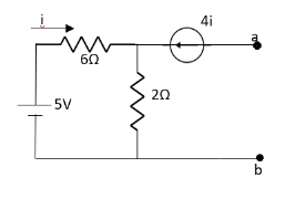
A8)
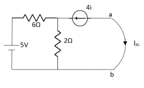
Fig. Circuit for finding Isc
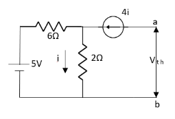
Fig. Circuit for finding Vth

Since, there is no significance of current source


 A
A
Q9) Find out the value of load resistance if power absorbed is maximum.
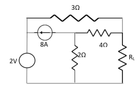
A9)
Find Thevenin’s equation

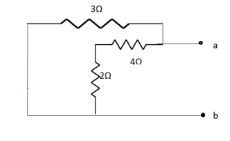
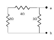
Fig. Finding Rth


Q10) Find maximum power delivered is RL if its value is

- 16Ω
 Ω
Ω- 60Ω
- 20Ω
A10)
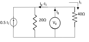
Fig. Circuit for finding Rth


Therefore, 
Q11) For the circuit as shown in figure. Calculate current I3. Let the value of resistance change by small value. Calculate the change in current I3.

A11)
Vs = 50V, R1 = 4 Ω, R2 = 15 Ω, R3 = 10 Ω, ∆R3 = 5Ω.
I3 = Vs R2/ R1.R2 + R2R3+ R1.R3 = 3A
Vc = (I3 ∆ R3) = 50 V
∆ I3 = -Vc / (R3 + ∆ R3) + R1. R2 / R1 + R2 = -19/23 A
Q12) For the circuit shown find the value of RL that absorbs maximum power from the circuit and the corresponding power under this condition.
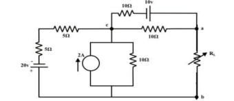
A12)
Load resistance RL is disconnected from the terminals ‘a’ and ‘b’ and the corresponding circuit diagram.
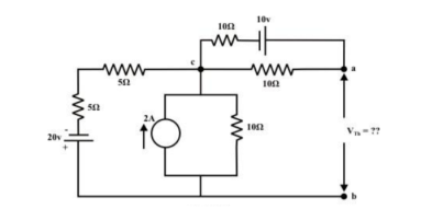
The above circuit is equivalently represented by a Thevenin circuit and the corresponding Thevenin voltage VTh and Thevenin resistance RTh are calculated by following the steps given below:
Considering 20V only
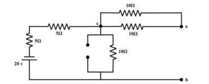
From the above circuit the current through ‘b-c’ branch =20/ 20 = 1𝐴 (𝑓𝑟𝑜𝑚𝑎𝑡𝑜𝑏). Whereas the voltage across the ‘b-a’ branch vba =1 ×10 =10 volt . Since ’b’ is higher potential than ‘a’∴vab = − 10volt.
Considering only 10v source only
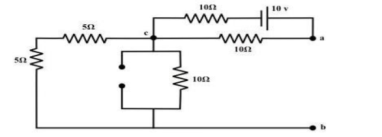
No current is flowing through ‘cb’-branch. Vab = 5v (‘a’ is higher potential than ‘b’).Consider only 2 A current source only
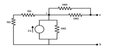
To compute Rth
Replace all voltage and current sources by their internal resistance of the circuit.
Rth = Rab = ((5+5)||10) + (10||10) = 5+5 =10Ω
RL = Rth = 10Ω
The maximum power dissipated to RL is
Pmax = Vth 2 / 4 Rth = ¼ 25 /10 = 0.625 watts
Q13) Find the maximum power that can be delivered to the load resistor RL of the circuit shown in the following figure.

A13)
Step 1 –Using Thevenin’s circuit we get
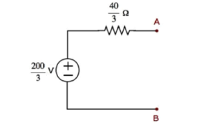
Thevenin’s voltage Vth = 200/3 and Thevenin’s resistance Rth = 40/3
Step 2 – Replace the left side of terminals A & B of the given circuit with the above Thevenin’s equivalent circuit. The resultant circuit diagram will be
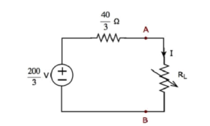
Step 3 − We can find the maximum power that will be delivered to the load resistor, RL by using the following formula.
PL,max = Vth 2 / 4 Rth
Substitute VTh=200/3and RTh=40/3Ω
PL,max = (200/3) 2 / 4 (40/3)
Therefore, the maximum power that will be delivered to the load resistor RL of the given circuit is 250/3 .
Q14) Find RN, IN, the current flowing through and load Voltage across the load resistor in fig (1) by using Norton’s Theorem.

A14)
Step 1:
Short the 1.5 Ω load resistor.
Step 2:
Norton current.
Short AB terminals to obtain IN . The total resistance of the circuit is
2Ω + (6Ω || 3Ω)
RT = 4 Ω
IT = V / RT = 12/ 4 = 3 A
IN = 3 A x [ 6Ω / 3 + 6 )] = 2A
IN = 2A
Step 3:
Open current sources, Short Voltage sources and Open Load resistor.
Step 4:
Calculate Norton Resistance (RN)
Reduce 12V dc source. 3Ω resistor is in series with combination of 6Ω and 2Ω resistor
3Ω + (6Ω||2Ω)
3Ω + 1.5 Ω = 4.5 Ω; RN = 4.5 Ω
Step 5:
Connect RN in parallel with current source IN and the load resistor.
Step 6:
The load current through Load resistor
IL = IN x [ RN/(RN + RL)
=2 A x ( 4.5 / 4.5 + 1.5 K) = 1.5 A
IL = 1.5 A
The voltage across load resistor
VL = IL x RL
= 1.5 x 1.5
VL = 2.25 V
Q15) For the circuit shown in figure, find the current IL through 6 Ω resistor using Thevenin’s theorem.

A15)
Step-1:
Disconnect 6 Ω from the terminals ‘a’ and ‘b’ and the corresponding circuit diagram. Consider point ‘g’ as ground potential and other voltages are measured with respect to this point.
Step-2:
Apply any suitable method to find the Thevenin’s voltage (VTh )
KVL is applied around the closed path ‘gcag’ to compute Thevenin’s voltage.
42 – 8I – 4I -30 = 0 ; I = 1A
Vag = 30+4 = 34 volt
Vbg = 2 x 3 = 6 volt
Vth = Vab = Vag – Vbg = 34 -6 = 28 volt
Step-3:
Thevenin’s resistance RTh can be found by replacing all sources by their internal resistances all voltage sources are short-circuited and current sources are just removed or open circuited.
Rth = (8 x4) / 12 + 2 = 14/3 = 4.666Ω
Step-4:
Thevenin’s equivalent circuit is now equivalently represents the original circuit

IL = Vth / Rth + RL = 28 / 4.666 +6 = 2.625 A
Q16) For the circuit as shown in figure find the current through RL = R2 = 1Ω resistor (Ia-b) branch using Thevenin’s theorem. Find the voltage across the current source.
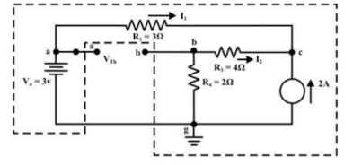
A16)
Step 1: Disconnect the load resistance and reconnect the circuit.
Step 2: Apply any method to calculate Vth
At node C
2 + I1 + I2 =0
2 + (3 -Vc)/3 + (0-Vc/6) --Vc = 6V
The currents I1 and I2 are computed by the following expressions:
I1 = Va -Vc/3 = 3-6/3 = -1A (I1 is flowing from c to a)
I2 = 0 – Vc/6 = -6/6 = -1A (I2 is flowing from c to a)
Step-3:
Redraw the circuit indicating the direction of currents in different branches. One can find the Thevenin’s voltage VTh using KVL around the closed path ‘gabg’
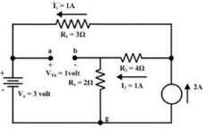
VTh = Vag−Vbg = 3 − 2 =1volt
Step 4:
Replace all sources by their internal resistances. In this problem, voltage source has an internal resistance zero (0) (ideal voltage source) and it is short-circuited with a wire.
On the other hand, the current source has an infinite internal resistance (ideal current source) and it is open-circuited (just remove the current source).
Thevenin’s resistance RTh of the fixed part of the circuit can be computed by looking at the load terminals ‘a’- ‘b’

RTh = ( R1 + R3 ) & R4 = ( 3 + 4 )&2 = 1.555Ω
Step-5: Place RTh in series with VTh to form the Thevenin’s equivalent circuit. Reconnect the original load resistance RL = R2 = 1 Ω to the Thevenin’s equivalent circuit.
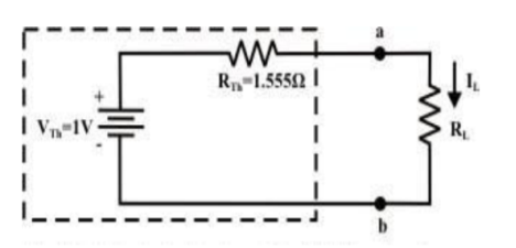

Step-6: The circuit is redrawn to indicate different branch currents. Referring to one can calculate the voltage Vbg and voltage across the current source (Vcg ) using the following equations.
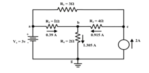
Vbg = Vag−Vab = 3 − 1 × 0.39 =2.61 volt.
Ibg = 2.61 2 = 1.305 A;
Icb = 1.305 − 0.39 = 0.915 A
Vcg = 4 × 0.915 + 2 ×1.305 =6.27 volt.
Q17) Verify the reciprocity theorem for the given network.

Find the current in branch AB
A17)
RT = 2+[3||(2 + 2 || 2)
RT = 3.5 Ω
IT = V / RT = 20/3.5 = 5.71 A
Apply current division technique for the circuit to find the current through branch AB
= 5.71 x 3 / 6 = 2.855 A
Current in branch AB = 2.855 x 2/4 = 1.43A
Interchanging the source to branch AB

Total resistance RT = 3.23Ω IT = 20/3.23 = 6.19A
Apply current division technique for the circuit to find current through branch CD = 6.19 x 2/5.2 = 2.38A
Current in branch CD = 2.38 x 3/5 = 1.43A
Hence reciprocity theorem verified.
Verify the reciprocity theorem for the given circuit:
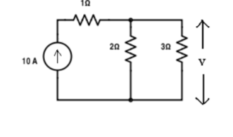
Apply current division technique for the circuit to find current through branch 3Ω
= 10 x 2 / 5 = 4 A.
Voltage across 3Ω = 4 x 3 = 12 V
Replace the current source and find the open circuit voltage.

Apply current division technique and find the current through 2 Ω resistor.
= 10 x 3 / 5 = 6
Voltage across 2Ω resistor = voltage across AB = 6 x 2 = 12 V
Q18) Using Superposition theorem determine the voltage drop and current across the resistor 3.3K as shown in figure below

A18)
Step 1:
Remove 8V power supply from the original circuit such that the new circuit becomes as the following and measure the voltage across resistor.
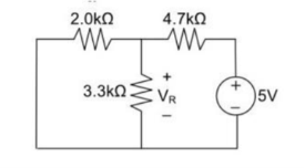
Here 3.3 K and 2K are in parallel therefore the resultant resistance will be 1.245K
Using voltage divider rule across 1.245K will be
V1 =[1.245/(1.245+4.7)] * 5 = 1.047V
Step 2:
Remove the 5V power supply from the original circuit such that the new circuit becomes the following and then measure the voltage across resistor.

Here 3.3K and 4.7K are in parallel therefore the resultant resistance will be 1.938K. Using voltage divider rule voltage across 1.938K will be
V2 =[1.938(1.938+2)] *8 = 3.9377V
Therefore, voltage drop across 3.3K resistor is V1+V2 = 1.047 + 3.9377 = 4.9847V
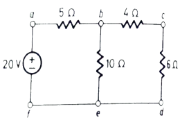
Q19) Verify Reciprocity theorem for given network?
A19)
The value of current Ix flowing due to 20V source is
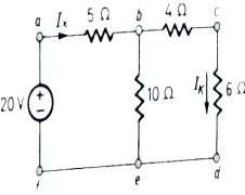
Fig. When 20V is at its place
Ix =  = 2A
= 2A
By current Division
Ik = Ix = 1A
= 1A
Now the voltage source of 20V is connected to branch cd. The current by source now will be given as
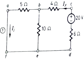
Fig. When 20V is connected to cd
Iy=  = 3/2 A
Then Ij = Iy = 1A
= 1A
From above we see that Ik = Ij = 1A
The reciprocity theorem is verified.
Q20) Using Tellegen’s theorem, find the voltage across 6A current source for the following circuit.
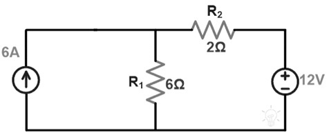
A20)
First, we need to calculate the current or voltage flowing throughout the circuit by applying KVL or KCL to the above network.
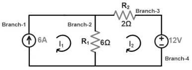
The flow of Current in Circuit
By applying KVL to the loop-2, we can get
-12 = 8I2 – 6I1
The flow of current throughout the branch including current source are I1 =6A;
Substitute this ‘I1’ value in the above equation; we can get ‘I2’ value.
-12 = 8I2 – 6I1
We know that I1 = 6A
-12 = 8I2 – 6(6)
-12 = 8I2 – 36
8I2 = 36 – 12 => 24
I2 = 3A
Flow of current throughout the branch-2 is;
I12 = I1 – I2 => 6 – 3 = 3A
I12 = 3A
Now, wneed to find the power for every branch
P1 = V I1 = V x 6 = 6 x V
P2 = R1 I122 = 6 x 9 = 54W
P3 = R2 I2^2 = 2 x 9 = 18W
P4 = V I2 = -12 x 3 = -36W
Here, energy sources are available in two branches. Thus, these branches can be considered as power delivering branches. Set the positive (+ve) sign to the instant power.
The remaining branches have only resistors. Thus, these are power absorbing branches & set the negative (-) sign to the instant power.
Both the powers like P1 & P4 have a positive sign whereas powers P2 & P3 have a negative sign.
Now, we need to add all instant power.
P1 – P2 – P3 + P4 = 0W
P1 – 54 – 18 + 36 = 108W
The power transmitted throughout the 6A current source is 108W. Thus the voltage across the 6A source of current can be calculated through the following equation.
P1 = V I
108W = V x 6A
V = 108/6 = 18V
So, the voltage across the 6A current source is 18V.