Unit - 5
Channel Coding (PART-II)
Q1) The generator matrix for a block code is given below. Find all code vectors of this code
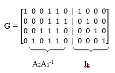
G = 
A1) The Generator matrix G is generally represented as
[G]kn =  kn
kn
 kn =
kn = 
On comparing,
The number of message bits, k = 3
The number of code word bits, n = 6
The number of check bits, q = n – k = 6 – 3 = 3
Hence, the code is a (6, 3) systematic linear block code. From the generator matrix, we have Identity matrix
Ikk = 
The coefficient or submatrix,
Pkq = 
Therefore, the check bits vector is given by,
[C]1q = [M]1k[P]kq
On substituting the matrix form,
[c1 c2 c3] = [m1 m2 m3]
From the matrix multiplication, we have
c1 = (1 m1) ⨁ (0 m2) ⨁ (1 m3)
c2 = (0 m1) ⨁ (1 m2) ⨁ (0 m3)
c3 = (0 m1) ⨁ (1 m2) ⨁ (1 m3)
On simplifying, we obtain
c1 = m1 ⨁ m3
c2 = m2
c3 = m2 ⨁ m3
Hence the check bits (c1 c2 c3) for each block of (m1 m2 m3) message bits can be determined.
(i) For the message block of (m1 m2 m3) = (0 0 0), we have
c1 = m1 ⨁ m3 = 0 ⨁ 0 = 0
c2 = m2 = 0
c3 = m2 ⨁ m3 = 0 ⨁ 0 = 0
(ii) For the message block of (m1 m2 m3) = (0 0 1), we have
c1 = m1 ⨁ m3 = 0 ⨁ 1 = 1
c2 = m2 = 0
c3 = m2 ⨁ m3 = 0 ⨁ 1 = 1
(iii) For the message block of (m1 m2 m3) = (0 1 0), we have
c1 = m1 ⨁ m3 = 0 ⨁ 0 = 0
c2 = m2 = 1
c3 = m2 ⨁ m3 = 1 ⨁ 0 = 1
Similarly, we can obtain check bits for other message blocks.
Q2) For a systematic (6,3) linear block code the parity matrix P is given by
P = 
- Find the possible code vector
- Draw the encoding circuit.
- Draw the syndrome calculation circuit for recorded vector
R = [r1 r2 r3 r4 r5 r6]
A2) Given n=6 and k=3 for (6,3) block code
Since k=3 there are 23 = 8 message vectors given by
(000),(001),(010),(011),(100),(101),(110),(111)
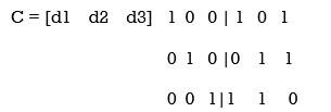
The code vector is found by
[C]= [D][G]
[G] = {Ik|P]= [I3|P]
1 0 0 | 1 0 1
0 1 0 |0 1 1
0 0 1|1 1 0
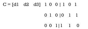
C= [d1,d2,d3,(d1+d3),(d2+d3),(d1+d2)]
Code name | Msg Vector | Code Vector For (6,3) liner block code |
| d 1 d 2 d3 | d 1 d 2 d 3 d 1+d 3 d2 + d3 d1 + d2 |
Ca | 0 0 0 | 0 0 0 0 0 0 |
Cb | 0 0 1 | 0 0 1 1 1 0 |
Cc | 0 1 0 | 0 1 0 0 1 1 |
Cd | 0 1 1 | 0 1 1 1 0 1 |
Ce | 1 0 0 | 1 0 0 1 0 1 |
Cf | 1 0 1 | 1 0 1 0 1 1 |
Cg | 1 1 0 | 1 1 0 1 1 0 |
Ch | 1 1 1 | 1 1 1 0 0 0 |
The code vector is given by
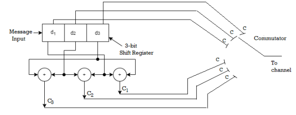
c 1 = d1 , c2 = d2 , c3 = d3 c4 = d1 + d3 c5 = d2 + d3 c6 = d1 + d2
Since k=3 we require 3bit shift registers to move the message bits into it.
We have (n-k) = 6-3 = 3.
Hence we require 3-modulo 2 adders and 6 segement commutator.
For the (6,3) code matrix HT is given by
H T =
1 | 0 | 1 |
0 | 1 | 1 |
1 | 1 | 0 |
1 | 0 | 0 |
0 | 1 | 0 |
0 | 0 | 1 |
H T = [P/In-k] = [P/I3]
S= [s1 s2 s3] = [ r1 r2 r3 r4 r5 r6]
1 | 0 | 1 |
0 | 1 | 1 |
1 | 1 | 0 |
1 | 0 | 0 |
0 | 1 | 0 |
0 | 0 | 1 |
[S] = [S1 s2 s3] = (r1+r3+r4) , (r2+r3+r5),(r1+r2+r6)
S1 = r1+r3+r4
S2 = r2+r3+r5
S3 = r1 +r2 +r6
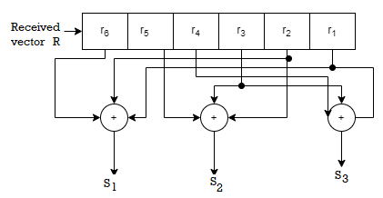
Fig 1 Syndrome calculation circuit
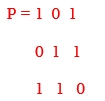
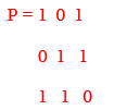
Q3) For a systematic (6,3) linear block code the parity marix P is given by
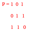
For the recorded code-vector R= [1 1 0 0 1 0] Detect and correct the single error that has occurred due to noise.
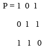
A3) Given
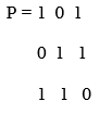
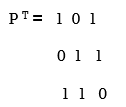
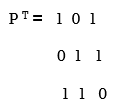
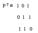
Parity check matrix [H] = [P T | I n-k] = [ PT | I3 ]
1 0 1 1 0 0
0 1 1 0 1 0
1 1 0 0 0 1
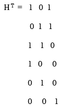
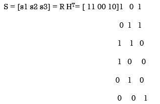
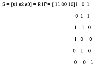
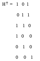
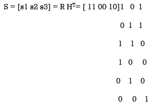
[S]= [100] since s≠0 it represents error. Since [100] present in the 4th row of HT . So the error vector [E] = [0 0 0 1 0 0 ] the the corrected vector is given by
C = R + E = [11 00 10][000100]
C = [110110] which is the valid code
Q4) The generator polynomial of a (7, 4) cyclic code is G(p) = p3 + p + 1. Find all the code vectors for the code in systematic form.
A4)
Here n = 7, k = 4
Therefore, q = n - k = 7 – 4 = 3
Since k = 4, there will be a total of 2k = 24 = 16 message vectors (From 0 0 0 0 to 1 1 1 1). Each can be coded into a 7 bits codeword.
(i) Consider any message vector as
M = (m3 m2 m1 m0) = (1 1 1 0)
By message polynomial,
M(p) = m3p3 + m2p2 + m1p + m0, for k = 4.
For the message vector (1 1 1 0), the polynomial is
M(p) = 1.p3 + 1.p2 + 1.p + 0.1
M(p) = p3 + p2 + p
The given generator polynomial is G(p) = p3 + p + 1
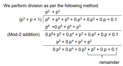
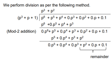
The check bits vector polynomial is
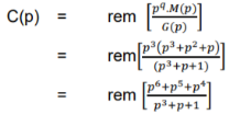

Thus, the remainder polynomial is p2 + 0.p + 0.1.
This is the check bits polynomial C(p)
c(p) = p2 + 0.p + 0.1
The check bits are c = (1 0 0)
Hence the code vector for the message vector (1 1 1 0) in systematic form is
X = (m3 m2 m1 m0⋮ c2 c1 c0) = (1 1 1 0 1 0 0)
(ii) Consider another message vector as
M = (m3 m2 m1 m0) = (1 0 1 0)
The message polynomial is M(p) = p3 + p
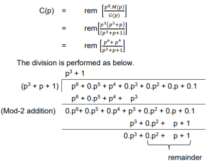
Then the check bits vector polynomial is
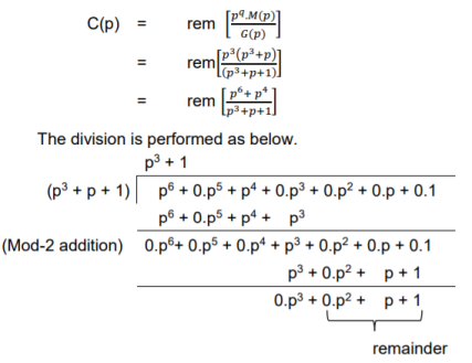
Thus, the check bits polynomial is C(p) = 0.p2 + 1.p + 1.1
The check bits are C = (0 1 1)
Hence the code vector is X= (1 0 1 0 0 1 1)
Similarly, we can find code vector for other message vectors also, using the same procedure.
Q5) Generate the CRC code for the data word of 1 1 1 0. The divisor polynomial is p3 + p + 1
A5)
Data Word (Message bits) = 1 1 1 0
Generator Polynomial (divisor) = p3 + p + 1
Divisor in binary form = 1 0 1 1
The divisor will be of (q + 1) bits long. Here the divisor is of 4 bits long. Hence q = 3. We append three 0s to the data word.
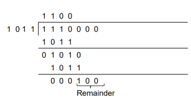
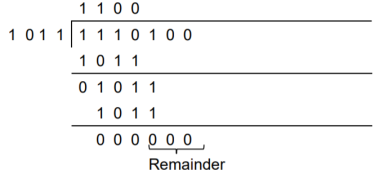
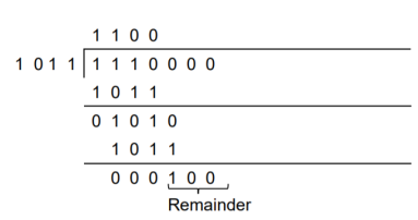
Now the data sequence is 1 1 1 0 0 0 0. We divide this data by the divisor of 1 0 1 1. Binary division is followed.
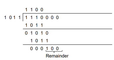
The remainder obtained from division is 100. Then the transmitted codeword is 1 1 1 0 1 0 0.
Q6) A codeword is received as 1 1 1 0 1 0 0. The generator (divisor) polynomial is p3 + p + 1. Check whether there is error in the received codeword.
A6)
Received Codeword = 1 1 1 0 1 0 0
Divisor in binary form = 1 0 1 1
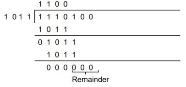
We divide the received codeword by the divisor.

The remainder obtained from division is zero. Hence there is no error in the received codeword.
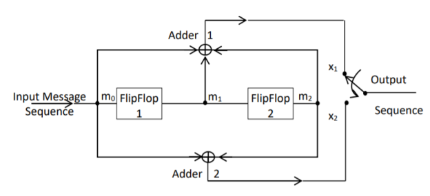
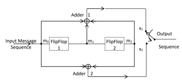
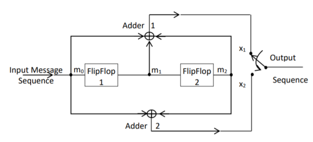
Q7) For the convolutional encoder given below in Figure, determine the following. a) Code rate b) Constraint length c) Dimension of the code d) Represent the encoder in graphical form.
A7)
a) Code rate:
The code rate, r = 𝑘/𝑛. The number of message bits, k = 1.
The number of encoder output bits, n = 2.
Hence code rate, r = 1/2
b) Constraint length:
Constraint length, k = 1 + number of shift registers.
Hence k = 1 + 2 = 3
c) Code dimension:
Code dimension = (n, k,K) = (2, 1, 3)
Hence the given encoder is of ½ rate convolutional encoder of dimension (2, 1, 3).
d) Graphical form representation
The encoder output is X = (x1 x2 x1 x2 x1 x2….. And so on)
The Mod-2 adder 1 output is x1 = m0 m1 m2
The Mod-2 adder 2 output is x2 = m0 m2.
We can represent the encoder output for possible input message bits in the form of a Logic table.
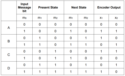
Output x1 = m0 m1 m2 and x2 = m0 m2
- The encoder output depends on the current input message bit and the contents in the shift register ie., the previous two bits.
- The present condition of the previous two bits in the shift register may be in four combinations. Let these combinations 00, 10, 01 and 11 be corresponds to the states A, B, C and D respectively.
- For each input message bit, the present state of the m1 and m2 bits will decide the encoded output.
- The logic table presents the encoded output x1 and x2 for the possible ‘0’ or ‘1’ bit input if the present state is A or B or C or D.
Q8) For given matrixes find standard array?
G =
0 | 1 | 1 | 1 | 0 | 0 |
1 | 0 | 1 | 0 | 1 | 0 |
1 | 1 | 0 | 0 | 0 | 1 |
H
1 | 0 | 0 | 0 | 1 | 1 |
0 | 1 | 0 | 1 | 0 | 1 |
0 | 0 | 1 | 1 | 1 | 0 |
A8)
The standard array has 6 coset leaders of weight 1 and weight 2.
000000 | 001110 | 010101 | 011011 | 100011 | 101101 | 110110 | 111000 |
000001 | 001111 | 010100 | 011010 | 100010 | 101100 | 110111 | 111001 |
000010 | 001100 | 010111 | 111001 | 100001 | 101111 | 110100 | 111010 |
000100 | 001010 | 010001 | 011111 | 100111 | 101001 | 110010 | 111011 |
001000 | 000110 | 011101 | 010011 | 101011 | 100101 | 111110 | 110000 |
010000 | 011110 | 000101 | 001011 | 110011 | 111101 | 100110 | 101000 |
100000 | 101110 | 110101 | 111011 | 000011 | 001101 | 010110 | 011000 |
001001 | 000111 | 011100 | 010010 | 101010 | 100100 | 111111 | 110001 |
Q9) How can we generate code vectors in systematic form of cyclic codes?
A9)
The code word for the systematic form of cyclic codes is given by
X = (k message bits ⋮q check bits)
X = (mk-1 mk-2 …….. m1 m0⋮ cq-1 cq-2….. c1 c0)
In polynomial form, the check bits vector can be written as
C(p) = cq-1pq-1 + cq-2pq-2 + …….. + c1p + c0
In systematic form, the check bits vector polynomial is obtained by
C(p) = rem [𝑝𝑞. 𝑀(𝑝)/𝐺(𝑝) ]
Where:
M(p) is message polynomial
G(p) is generating polynomial
‘rem’ is remainder of the division
Q10) How a code vector can be generated in non-systematic form of cyclic codes?
A10)
Let M = (mk-1, mk-2, …… m1, m0) be ‘k’ bits of message vector. Then it can be represented by the polynomial as,
M(p) = mk-1pk-1 + mk-2pk-2 + ……+ m1p + m0
The codeword polynomial X(P) is given as X (P) = M(P) . G(P)
Where G(P) is called as the generating polynomial of degree ‘q’ (parity or check bits q = n – k). The generating polynomial is given as G (P) = pq + gq-1pq-1+ …….. + g1p + 1
Here gq-1, gq-2….. g1 are the parity bits.
• If M1, M2, M3, …… etc. are the other message vectors, then the corresponding code vectors can be calculated as,
X1 (P) = M1 (P) G (P)
X2 (P) = M2 (P) G (P)
X3 (P) = M3 (P) G (P) and so on
All the above code vectors X1, X2, X3….. Are in non-systematic form and they satisfy cyclic property.
Q11) What are cyclic codes explain?
A11)
Binary cyclic codes are a subclass of the linear block codes. They have very good features which make them extremely useful. Cyclic codes can correct errors caused by bursts of noise that affect several successive bits. The very good block codes like the Hamming codes, BCH codes and Golay codes are also cyclic codes. A linear block code is called as cyclic code if every cyclic shift of the code vector produces another code vector. A cyclic code exhibits the following two properties.
(i) Linearity Property: A code is said to be linear if modulo-2 addition of any two code words will produce another valid codeword.
(ii) (ii) Cyclic Property: A code is said to be cyclic if every cyclic shift of a code word produces another valid code word. For example, consider the n-bit code word, X = (xn-1, xn-2, ….. x1, x0).
If we shift the above code word cyclically to left side by one bit, then the resultant code word is
X’ = (xn-2, xn-3, ….. x1, x0, xn-1)
Here X’ is also a valid code word. One more cyclic left shift produces another valid code vector X’’.
X’’ = (xn-3, xn-4, ….. x1, x0, xn-1, xn-2)
Representation of codewords by a polynomial
• The cyclic property suggests that we may treat the elements of a code word of length n as the coefficients of a polynomial of degree (n-1).
• Consider the n-bit code word, X = (xn-1, xn-2, ….. x1, x0)
This code word can be represented in the form of a code word polynomial as below:
X (p) = xn-1p n-1 + xn-2pn-2 + ….. + x1p + x0
Where X (p) is the polynomial of degree (n-1). p is an arbitrary real variable. For binary codes, the coefficients are 1s or 0s.
- The power of ‘p’ represents the positions of the code word bits. i.e., pn-1 represents MSB and p0 represents LSB.
- Each power of p in the polynomial X(p) represents a one-bit cyclic shift in time. Hence, multiplication of the polynomial X(p) by p may be viewed as a cyclic shift or rotation to the right, subject to the constraint that pn = 1.
- We represent cyclic codes by polynomial representation because of the following reasons.
1. These are algebraic codes. Hence algebraic operations such as addition, subtraction, multiplication, division, etc. becomes very simple.
2. Positions of the bits are represented with the help of powers of p in a polynomial.
Q12) Explain with the diagram CRC encoder?
A12) Cyclic codes are extremely well-suited for error detection. Because they can be designed to detect many combinations of likely errors. Also, the implementation of both encoding and error detecting circuits is practical. For these reasons, all the error detecting codes used in practice are of cyclic code type. Cyclic Redundancy Check (CRC) code is the most important cyclic code used for error detection in data networks & storage systems. CRC code is basically a systematic form of cyclic code.
CRC Generation (encoder)
The CRC generation procedure is shown in the figure below.
- Firstly, we append a string of ‘q’ number of 0s to the data sequence. For example, to generate CRC-6 code, we append 6 number of 0s to the data.
- We select a generator polynomial of (q+1) bits long to act as a divisor. The generator polynomials of three CRC codes have become international standards. They are
- CRC – 12 code: p12 + p11 + p3 + p2 + p + 1
- CRC – 16 code: p16 + p15 + p2 + 1
- CRC – CCITT Code: p16 + p12 + p5 + 1
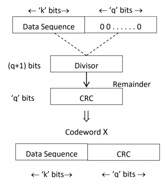
Fig 2 CRC Generation
- We divide the data sequence appended with 0s by the divisor. This is a binary division.
- The remainder obtained after the division is the ‘q’ bit CRC. Then, this ‘q’ bit CRC is appended to the data sequence. Actually, CRC is a sequence of redundant bits.
- The code word generated is now transmitted.
Q13) What is convolution code. Explain convolution encoder?
A13) In block coding, the encoder accepts a k-bit message block and generates an n-bit code word. Thus, code words are produced on a block-by-block basis. Therefore, a buffer is required in the encoder to place the message block. A subclass of Tree codes is convolutional codes. The convolutional encoder accepts the message bits continuously and generates the encoded codeword sequence continuously. Hence there is no need for buffer. But in convolutional codes, memory is required to implement the encoder.
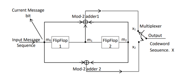
Fig 3. Convolutional Encoder
In a convolutional code, the encoding operation is the discrete-time convolution of the input data sequence with the impulse response of the encoder. The input message bits are stored in the fixed length shift register and they are combined with the help of mod-2 adders. This operation is equivalent to binary convolution and hence it is called convolutional coding. The figure above shows the connection diagram for an example convolutional encoder.
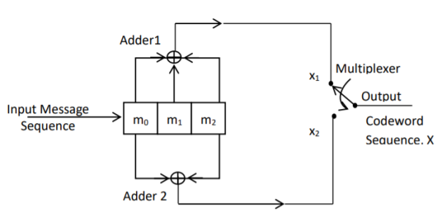
Fig 4. Convolutional Encoder redrawn alternatively
The encoder of a binary convolution code may be viewed as a finite-state machine. It consists of M-stage shift register with prescribed connections to modulo2 adders. A multiplexer serializes the outputs of the adders. The convolutional codes generated by these encoders of Figure above are non-systematic form. Consider that the current message bit is shifted to position m0. Then m1 and m2 store the previous two message bits. Now, by mod-2 adders 1 and 2 we get the new values of X1 and X2. We can write
X1 = m0 m1 m2 and
X2 = m0 m2
The multiplexer switch first samples X1 and then X2. Then next input bit is taken and stored in m0. The shift register then shifts the bit already in m0 to m1. The bit already in m1 is shifted to m2. The bit already in m2 is discarded. Again, X1 and X2 are generated according to this new combination of m0, m1 and m2. This process is repeated for each input message bit. Thus, the output bit stream for successive input bits will be,
X = x1 x2 x1 x2 x1 x2…….. And so on
In this convolutional encoder, for every input message bit, two encoded output bits X1 and X2 are transmitted. Hence number of message bits, k = 1. The number of encoded output bits for one message bit, n = 2.
Q14) Explain the state diagram representation of convolution code?
A14) State diagram representation
- The state of a convolutional encoder is defined by the contents of the shift register. The number of states is given by 2k-1 = 23-1 = 22 = 4. Here K represents the constraint length.
- Let the four states be A = 00, B = 10, C = 01 and D = 11 as per the logic table. A state diagram as shown in the figure below illustrates the functioning of the encoder.
- Suppose that the contents of the shift register is in the state A = 00. At this state, if the incoming message bit is 0, the encoder output is X = (x1 x2) = 00. Then if the m0, m1 and m2 bits are shifted, the contents of the shift register will also be in state A = 00. This is represented by a solid line path starting from A and ending at A itself.
- At the ‘A’ state, if the incoming message bit is 1, then the encoder output is X = 11. Now if the m0, m1 and m2 bits are shifted, the contents of the shift register will become the state B = 10. This is represented by a dashed line path starting from A and ending at B.
- Similarly, we can draw line paths for all other states, as shown in the Figure below.
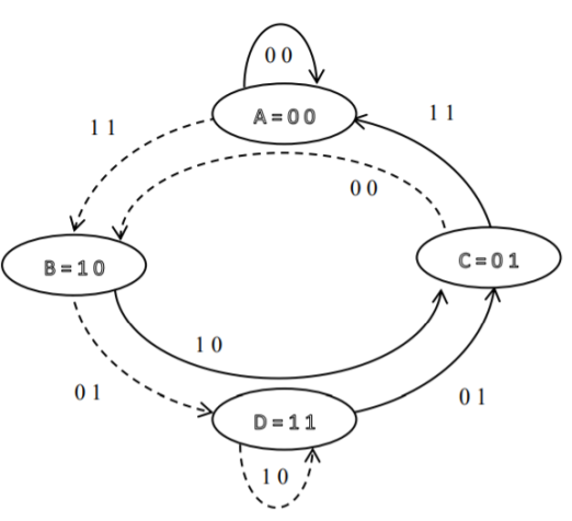
Fig 5. State Diagram
Q15) Explain the code tree representation of convolution code?
A15)
Code tree representation
- The code tree diagram is a simple way of describing the encoding procedure. By traversing the diagram from left to right, each tree branch depicts the encoder output codeword.
- Figure below shows the code representation for this encoder.
- The code tree diagram starts at state A =00. Each state now represents the node of a tree. If the input message bit is m0 = 0 at node A, then path of the tree goes upward towards node A and the encoder output is 00. Otherwise, if the input message bit is m0 = 1, the path of the tree goes down towards node B and the encoder output is 11.
- Similarly depending upon the input message bit, the path of the tree goes upward or downward. On the path between two nodes the outputs are shown.
- In the code tree, the branch pattern begins to repeat after third bit, since particular message bit is stored in the shift registers of the encoder for three shifts.
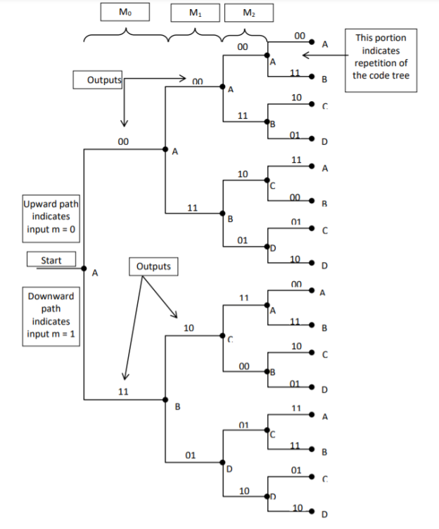
Fig 6. Code Tree Representation
Q16) Explain the code trellis representation of convolution code?
A16)
Code trellis representation
- Code trellis is the more compact representation of the code tree. In the code tree there are four states (or nodes). Every state goes to some other state depending upon the input message bit.
- Code trellis represents the single and unique diagram for such steady state transitions. The Figure below shows the code trellis diagram.
- The nodes on the left denote four possible current states and those on the right represents next state. The solid transition line represents for input message m0 = 0 and dashed line represents input message m0 = 1.
- Along with each transition line, the encoder output x1 x2 is represented during that transition.
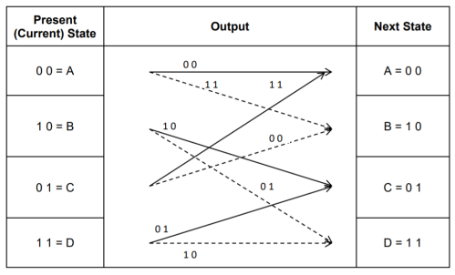
Fig 7. Code Trellis
Q17) Compare Linear block codes and convolution codes?
A17)

Q18) Write short notes on turbo codes?
A18)
The use of a good code with random-like properties is basic to turbo coding. In the first successful implementation of turbo codes11, Berrouet al. Achieved this design objective by using concatenated codes. The original idea of concatenated codes was conceived by Forney (1966). To be more specific, concatenated codes can be of two types: parallel or serial. The type of concatenated codes used by Berrou et al. Was of the parallel type, which is discussed in this section
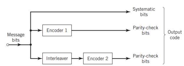
Fig 8. Block diagram of turbo encoder of the parallel type.
Figure above depicts the most basic form of a turbo code generator that consists of two constituent systematic encoders, which are concatenated by means of an interleaver. The interleaver is an input–output mapping device that permutes the ordering of a sequence of symbols from a fixed alphabet in a completely deterministic manner; that is, it takes the symbols at the input and produces identical symbols at the output but in a different temporal order. Turbo codes use a pseudo-random interleaver, which operates only on the systematic (i.e., message) bits. The size of the interleaver used in turbo codes is typically very large, on the order of several thousand bits. There are two reasons for the use of an interleaver in a turbo code:
1. The interleaver ties together errors that are easily made in one half of the turbo code to errors that are exceptionally unlikely to occur in the other half; this is indeed one reason why the turbo code performs better than a traditional code.
2. The interleaver provides robust performance with respect to mismatched decoding, a problem that arises when the channel statistics are not known or have been incorrectly specified.
Ordinarily, but not necessarily, the same code is used for both constituent encoders in Figure above. The constituent codes recommended for turbo codes are short constraint length RSC codes. The reason for making the convolutional codes recursive (i.e., feeding one or more of the tap outputs in the shift register back to the input) is to make the internal state of the shift register depend on past outputs. This affects the behavior of the error patterns, with the result that a better performance of the overall coding strategy is attained.
Q19) Explain two state turbo encoder in detail?
A19) Two-State Turbo Encoder Figure below shows the block diagram of a specific turbo encoder using an identical pair of two-state RSC constituent encoders. The generator matrix of each constituent encoder is given by
G(D)= (1, 1/1+D)
The input sequence of bits has length, made up of three message bits and one termination bit. The input vector is given by
m= m0 m1 m2 m3

Fig 9. Two-state turbo encoder for Example
The parity-check vector produced by the first constituent encoder is given by
b(1) = (b0(1), b1(1), b2(1), b3(1))
Similarly, the parity – check produced by the second constituent encoder is given by
b(2)= (b0(2), b0(2), b0(2), b0(2))
The transmitted code vector is therefore defined by
c = (c(0), c(1), c(2))
With the convolutional code being systematic, we thus have
c(0) = m
As for the remaining two sub-vectors constituting the code vector c, they are defined by
c(1) = b(1)
And
c(2) = b(2)
The transmitted code vector c is therefore made up of 12 bits. However, recalling that the termination bit m3 is not a message bit, it follows that the code rate of the turbo code is
R=3/12=1/4
Q20) Explain the extrinsic form of turbo decoder?
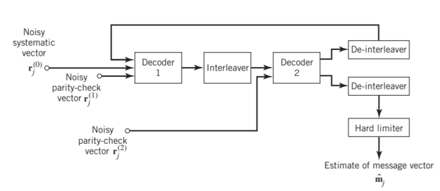
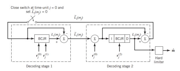
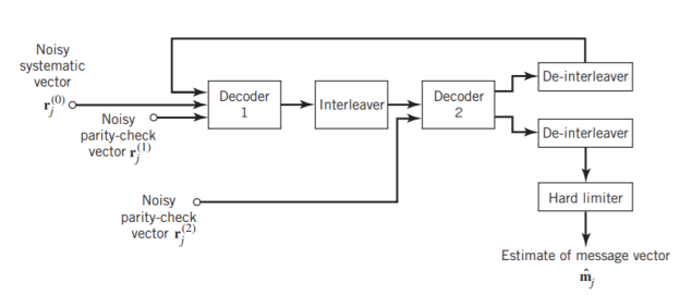
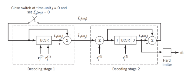
A20) Figure (a) below shows the block diagram of the two-stage turbo decoder. The decoder operates on noisy versions of the systematic bits and the two sets of parity-check bits in two decoding stages to produce an estimate of the original message bits[5]. A distinctive feature of the turbo decoder that is immediately apparent from the block diagram of Figure(a) is the use of feedback, manifesting itself in producing extrinsic information from one decoder to the next in an iterative manner. In a way, this decoding process is analogous to the feedback of exhaust gases experienced in a turbo-charged engine; indeed, turbo codes derive their name from this analogy. In other words, the term “turbo” in turbo codes has more to do with the decoding rather than the encoding process. In operational terms, the turbo encoder in Figure11(a) operates on noisy versions of the following inputs, obtained by demultiplexing the channel output, rj
- Systematic (i.e., message) bits, denoted by rj(0)
- Parity-check bits corresponding to encoder 1 in Figure encoder, denoted by rj(1)
- Parity-check bits corresponding to encoder 2 in Figure encoder, denoted by rj(2)
The net result of the decoding algorithm, given the received vector rj, is an estimate of the original message vector, namely, which is delivered at the decoder output to the user. Another important point to note in the turbo decoder of Figure 11(a) is the way in which the interleaver and de-interleaver are positioned inside the feedback loop. Bearing in mind the fact that the definition of extrinsic information requires the use of intrinsic information, we see that decoder 1 operates on three inputs:
- The noisy systematic (i.e., original message) bits,
- The noisy parity-check bits due to encoder 1, and
- De-interleaved extrinsic information computed by decoder 2
(a)
(b)
Fig 10(a) Block diagram of turbo decoder. (b) Extrinsic form of turbo decoder, where I stand for interleaver, D for deinterleaver, and BCJR for BCJR for BCJR algorithm for log-MAP decoding [5].
In a complementary manner, decoder 2 operates on two inputs of its own:
- The noisy parity-check bits due to encoder 2 and
- The interleaved version of the extrinsic information computed by decoder 1.
- For this iterative exchange of information between the two decoders inside the feedback loop to continuously reinforce each other, the de-interleaver and interleaver would have to separate the two decoders in the manner depicted in Figure a. Moreover, the structure of the decoder in the receiver is configured to be consistent with the structure of the encoder in the transmitter.
Q21) Explain advantages of LDPC codes and explain the code in details?
A21)
The two most important advantages of LDPC codes over turbo codes are:
- Absence of low-weight codewords and
- Iterative decoding of lower complexity.
With regard to the issue of low-weight codewords, we usually find that a small number of codewords in a turbo codeword are undesirably close to the given codeword. Owing to this closeness in weights, once in a while the channel noise causes the transmitted codeword to be mistaken for a nearby code.
In contrast, LDPC codes can be easily constructed so that they do not have such low-weight codewords and they can, therefore, achieve vanishingly small BERs. Turning next to the issue of decoding complexity, we note that the computational complexity of a turbo decoder is dominated by the MAP algorithm, which operates on the trellis for representing the convolutional code used in the encoder. The number of computations in each recursion of the MAP algorithm scales linearly with the number of states in the trellis. Commonly used turbo codes employ trellises with 16 states or more. In contrast, LDPC codes use a simple parity-check trellis that has just two states. Consequently, the decoders for LDPC codes are significantly simpler to design than those for turbo decoders. However, a practical objection to the use of LDPC codes is that, for large block lengths, their encoding complexity is high compared with turbo codes. It can be argued that LDPC codes and turbo codes complement each other, giving the designer more flexibility in selecting the right code for extraordinary decoding performance.
Construction of LDPC Codes
LDPC codes are specified by a parity-check matrix denoted by A, which is purposely chosen to be sparse; that is, the code consists mainly of 0s and a small number of 1s. In particular, we speak of (n, tc, tr) LDPC codes, where n denotes the block length, tc denotes the weight (i.e., number of 1s) in each column of the matrix A, and tr denotes the weight of each row with tr >tc. The rate of such an LDPC code is defined by
r = 1 – tc/tr
Whose validity may be justified as follows. Let denote the density of 1s in the parity check matrix A.
tc = (n-k)
tr = n
Where (n – k) is the number of rows in A and n is the number of columns (i.e., the block length). Therefore, dividing tc by tr, we get
tc/tr = 1 – k/n
The structure of LDPC codes is well portrayed by bipartite graphs, which were introduced by Tanner (1981) and, therefore, are known as Tanner graphs. Figure below shows such a graph for the example code of n = 10, tc = 3, and tr = 5. The left-hand nodes in the graph are variable (symbol) nodes, which correspond to elements of the codeword. The right-hand nodes of the graph are check nodes, which correspond to the set of parity-check constraints satisfied by codewords in the code. LDPC codes of the type exemplified by the graph of Figure below are said to be regular, in that all the nodes of a similar kind have exactly the same degree. In Figure below, the degree of the variable nodes is tc = 3 and the degree of the check nodes is tr = 5. As the block length n approaches infinity, each check node is connected to a vanishingly small fraction of variable nodes; hence the term “low density.”

Fig 11. Bipartite graph of the (10, 3, 5) LDPC code [5]
The matrix A is constructed by putting 1s in A at random, subject to the regularity constraints:
- Each column of matrix A contains a small fixed number tc of 1s;
- Each row of the matrix contains a small fixed number tr of 1s.
In practice, these regularity constraints are often violated slightly in order to avoid having linearly dependent rows in the parity-check matrix A.
The parity-check matrix A of LDPC codes is not systematic (i.e., it does not have the parity-check bits appearing in diagonal form); hence the use of a symbol different from that used in Section 10.4. Nevertheless, for coding purposes, we may derive a generator matrix G for LDPC codes by means of Gaussian elimination performed in modulo-2 arithmetic. The 1-by-n code vector c is first partitioned as shown by
c = [ b | m]
Where m is the k-by-1 message vector and b is the (n – k)-by-1 parity-check vector. Correspondingly, the parity-check matrix A is partitioned as
AT = 
Where A1 is a square matrix of dimensions (n – k) (n – k) and A2 is a rectangular matrix of dimensions k (n – k); transposition symbolized by the superscript T is used in the partitioning of matrix A for convenience of presentation. Imposing a constraint on the LDPC code we may write
[b | m] = 0
= 0
BA1 + mA2 = 0
The vectors m and b are related by
b=mP
The coefficient matrix of LDPC codes satisfies the condition
PA1 + A2 = 0
For matrix P, we get
P =A2A1-1
The generator matrix of LDPC codes is defined by
G = [ P | Ik]
=[A2A1-1 | Ik]
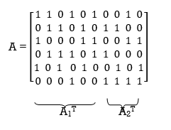
Consider the Tanner graph pertaining to a (10, 3, 5) LDPC code. The parity-check matrix of the code is defined by
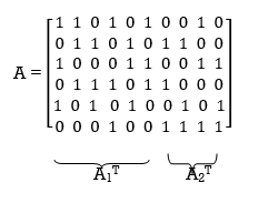
Which appears to be random, while maintaining the regularity constraints: tc = 3 and tr = 5. Partitioning the matrix A in the manner just described, we write
A1 = 
A2 = 
To derive the inverse of matrix A1
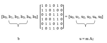
Where we have introduced the vector u to denote the matrix product mA2. By using Gaussian elimination, modulo-2, the matrix A1 is transformed into lower diagonal form (i.e., all the elements above the main diagonal are zero), as shown by
A1 
This transformation is achieved by the following modulo-2 additions performed on the columns of square matrix A1:
- Columns 1 and 2 are added to column 3;
- Column 2 is added to column 4;
- Columns 1 and 4 are added to column 5;
- Columns 1, 2, and 5 are added to column 6.
Correspondingly, the vector u is transformed as shown by
u [u0, u1, u0 + u1 + u2, u1 +u3, u0 + u3 + u4, u0 + u1 + u4 + u5]
Accordingly, pre multiplying the transformed matrix A1 by the parity vector b, using successive eliminations in modulo-2 arithmetic working backwards and putting the solutions for the elements of the parity vector b in terms of the elements of the vector u in matrix form, we get
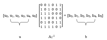
The inverse of matrix A1 is therefore
A1-1 = 
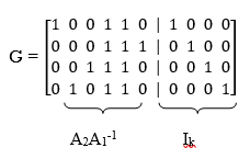
Using the given value of A2 and A1-1 the value of just found, the matrix product A2A1-1 is given by
A2A1-1 = 
LDPC code is defined by
Unit - 5
Unit - 5
Channel Coding (PART-II)
Q1) The generator matrix for a block code is given below. Find all code vectors of this code
G = 
A1) The Generator matrix G is generally represented as
[G]kn =  kn
kn
 kn =
kn = 
On comparing,
The number of message bits, k = 3
The number of code word bits, n = 6
The number of check bits, q = n – k = 6 – 3 = 3
Hence, the code is a (6, 3) systematic linear block code. From the generator matrix, we have Identity matrix
Ikk = 
The coefficient or submatrix,
Pkq = 
Therefore, the check bits vector is given by,
[C]1q = [M]1k[P]kq
On substituting the matrix form,
[c1 c2 c3] = [m1 m2 m3]
From the matrix multiplication, we have
c1 = (1 m1) ⨁ (0 m2) ⨁ (1 m3)
c2 = (0 m1) ⨁ (1 m2) ⨁ (0 m3)
c3 = (0 m1) ⨁ (1 m2) ⨁ (1 m3)
On simplifying, we obtain
c1 = m1 ⨁ m3
c2 = m2
c3 = m2 ⨁ m3
Hence the check bits (c1 c2 c3) for each block of (m1 m2 m3) message bits can be determined.
(i) For the message block of (m1 m2 m3) = (0 0 0), we have
c1 = m1 ⨁ m3 = 0 ⨁ 0 = 0
c2 = m2 = 0
c3 = m2 ⨁ m3 = 0 ⨁ 0 = 0
(ii) For the message block of (m1 m2 m3) = (0 0 1), we have
c1 = m1 ⨁ m3 = 0 ⨁ 1 = 1
c2 = m2 = 0
c3 = m2 ⨁ m3 = 0 ⨁ 1 = 1
(iii) For the message block of (m1 m2 m3) = (0 1 0), we have
c1 = m1 ⨁ m3 = 0 ⨁ 0 = 0
c2 = m2 = 1
c3 = m2 ⨁ m3 = 1 ⨁ 0 = 1
Similarly, we can obtain check bits for other message blocks.
Q2) For a systematic (6,3) linear block code the parity matrix P is given by
P = 
- Find the possible code vector
- Draw the encoding circuit.
- Draw the syndrome calculation circuit for recorded vector
R = [r1 r2 r3 r4 r5 r6]
A2) Given n=6 and k=3 for (6,3) block code
Since k=3 there are 23 = 8 message vectors given by
(000),(001),(010),(011),(100),(101),(110),(111)
The code vector is found by
[C]= [D][G]
[G] = {Ik|P]= [I3|P]
1 0 0 | 1 0 1
0 1 0 |0 1 1
0 0 1|1 1 0
C= [d1,d2,d3,(d1+d3),(d2+d3),(d1+d2)]
Code name | Msg Vector | Code Vector For (6,3) liner block code |
| d 1 d 2 d3 | d 1 d 2 d 3 d 1+d 3 d2 + d3 d1 + d2 |
Ca | 0 0 0 | 0 0 0 0 0 0 |
Cb | 0 0 1 | 0 0 1 1 1 0 |
Cc | 0 1 0 | 0 1 0 0 1 1 |
Cd | 0 1 1 | 0 1 1 1 0 1 |
Ce | 1 0 0 | 1 0 0 1 0 1 |
Cf | 1 0 1 | 1 0 1 0 1 1 |
Cg | 1 1 0 | 1 1 0 1 1 0 |
Ch | 1 1 1 | 1 1 1 0 0 0 |
The code vector is given by
c 1 = d1 , c2 = d2 , c3 = d3 c4 = d1 + d3 c5 = d2 + d3 c6 = d1 + d2
Since k=3 we require 3bit shift registers to move the message bits into it.
We have (n-k) = 6-3 = 3.
Hence we require 3-modulo 2 adders and 6 segement commutator.

For the (6,3) code matrix HT is given by
H T =
1 | 0 | 1 |
0 | 1 | 1 |
1 | 1 | 0 |
1 | 0 | 0 |
0 | 1 | 0 |
0 | 0 | 1 |
H T = [P/In-k] = [P/I3]
S= [s1 s2 s3] = [ r1 r2 r3 r4 r5 r6]
1 | 0 | 1 |
0 | 1 | 1 |
1 | 1 | 0 |
1 | 0 | 0 |
0 | 1 | 0 |
0 | 0 | 1 |
[S] = [S1 s2 s3] = (r1+r3+r4) , (r2+r3+r5),(r1+r2+r6)
S1 = r1+r3+r4
S2 = r2+r3+r5
S3 = r1 +r2 +r6
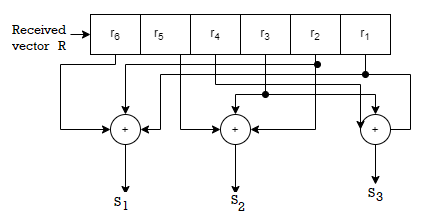
Fig 1 Syndrome calculation circuit
Q3) For a systematic (6,3) linear block code the parity marix P is given by
For the recorded code-vector R= [1 1 0 0 1 0] Detect and correct the single error that has occurred due to noise.
A3) Given
Parity check matrix [H] = [P T | I n-k] = [ PT | I3 ]
1 0 1 1 0 0
0 1 1 0 1 0
1 1 0 0 0 1

[S]= [100] since s≠0 it represents error. Since [100] present in the 4th row of HT . So the error vector [E] = [0 0 0 1 0 0 ] the the corrected vector is given by
C = R + E = [11 00 10][000100]
C = [110110] which is the valid code
Q4) The generator polynomial of a (7, 4) cyclic code is G(p) = p3 + p + 1. Find all the code vectors for the code in systematic form.
A4)
Here n = 7, k = 4
Therefore, q = n - k = 7 – 4 = 3
Since k = 4, there will be a total of 2k = 24 = 16 message vectors (From 0 0 0 0 to 1 1 1 1). Each can be coded into a 7 bits codeword.
(i) Consider any message vector as
M = (m3 m2 m1 m0) = (1 1 1 0)
By message polynomial,
M(p) = m3p3 + m2p2 + m1p + m0, for k = 4.
For the message vector (1 1 1 0), the polynomial is
M(p) = 1.p3 + 1.p2 + 1.p + 0.1
M(p) = p3 + p2 + p
The given generator polynomial is G(p) = p3 + p + 1
The check bits vector polynomial is

Thus, the remainder polynomial is p2 + 0.p + 0.1.
This is the check bits polynomial C(p)
c(p) = p2 + 0.p + 0.1
The check bits are c = (1 0 0)
Hence the code vector for the message vector (1 1 1 0) in systematic form is
X = (m3 m2 m1 m0⋮ c2 c1 c0) = (1 1 1 0 1 0 0)
(ii) Consider another message vector as
M = (m3 m2 m1 m0) = (1 0 1 0)
The message polynomial is M(p) = p3 + p
Then the check bits vector polynomial is
Thus, the check bits polynomial is C(p) = 0.p2 + 1.p + 1.1
The check bits are C = (0 1 1)
Hence the code vector is X= (1 0 1 0 0 1 1)
Similarly, we can find code vector for other message vectors also, using the same procedure.
Q5) Generate the CRC code for the data word of 1 1 1 0. The divisor polynomial is p3 + p + 1
A5)
Data Word (Message bits) = 1 1 1 0
Generator Polynomial (divisor) = p3 + p + 1
Divisor in binary form = 1 0 1 1
The divisor will be of (q + 1) bits long. Here the divisor is of 4 bits long. Hence q = 3. We append three 0s to the data word.
Now the data sequence is 1 1 1 0 0 0 0. We divide this data by the divisor of 1 0 1 1. Binary division is followed.
The remainder obtained from division is 100. Then the transmitted codeword is 1 1 1 0 1 0 0.
Q6) A codeword is received as 1 1 1 0 1 0 0. The generator (divisor) polynomial is p3 + p + 1. Check whether there is error in the received codeword.
A6)
Received Codeword = 1 1 1 0 1 0 0
Divisor in binary form = 1 0 1 1
We divide the received codeword by the divisor.
The remainder obtained from division is zero. Hence there is no error in the received codeword.
Q7) For the convolutional encoder given below in Figure, determine the following. a) Code rate b) Constraint length c) Dimension of the code d) Represent the encoder in graphical form.
A7)
a) Code rate:
The code rate, r = 𝑘/𝑛. The number of message bits, k = 1.
The number of encoder output bits, n = 2.
Hence code rate, r = 1/2
b) Constraint length:
Constraint length, k = 1 + number of shift registers.
Hence k = 1 + 2 = 3
c) Code dimension:
Code dimension = (n, k,K) = (2, 1, 3)
Hence the given encoder is of ½ rate convolutional encoder of dimension (2, 1, 3).
d) Graphical form representation
The encoder output is X = (x1 x2 x1 x2 x1 x2….. And so on)
The Mod-2 adder 1 output is x1 = m0 m1 m2
The Mod-2 adder 2 output is x2 = m0 m2.
We can represent the encoder output for possible input message bits in the form of a Logic table.

Output x1 = m0 m1 m2 and x2 = m0 m2
- The encoder output depends on the current input message bit and the contents in the shift register ie., the previous two bits.
- The present condition of the previous two bits in the shift register may be in four combinations. Let these combinations 00, 10, 01 and 11 be corresponds to the states A, B, C and D respectively.
- For each input message bit, the present state of the m1 and m2 bits will decide the encoded output.
- The logic table presents the encoded output x1 and x2 for the possible ‘0’ or ‘1’ bit input if the present state is A or B or C or D.
Q8) For given matrixes find standard array?
G =
0 | 1 | 1 | 1 | 0 | 0 |
1 | 0 | 1 | 0 | 1 | 0 |
1 | 1 | 0 | 0 | 0 | 1 |
H
1 | 0 | 0 | 0 | 1 | 1 |
0 | 1 | 0 | 1 | 0 | 1 |
0 | 0 | 1 | 1 | 1 | 0 |
A8)
The standard array has 6 coset leaders of weight 1 and weight 2.
000000 | 001110 | 010101 | 011011 | 100011 | 101101 | 110110 | 111000 |
000001 | 001111 | 010100 | 011010 | 100010 | 101100 | 110111 | 111001 |
000010 | 001100 | 010111 | 111001 | 100001 | 101111 | 110100 | 111010 |
000100 | 001010 | 010001 | 011111 | 100111 | 101001 | 110010 | 111011 |
001000 | 000110 | 011101 | 010011 | 101011 | 100101 | 111110 | 110000 |
010000 | 011110 | 000101 | 001011 | 110011 | 111101 | 100110 | 101000 |
100000 | 101110 | 110101 | 111011 | 000011 | 001101 | 010110 | 011000 |
001001 | 000111 | 011100 | 010010 | 101010 | 100100 | 111111 | 110001 |
Q9) How can we generate code vectors in systematic form of cyclic codes?
A9)
The code word for the systematic form of cyclic codes is given by
X = (k message bits ⋮q check bits)
X = (mk-1 mk-2 …….. m1 m0⋮ cq-1 cq-2….. c1 c0)
In polynomial form, the check bits vector can be written as
C(p) = cq-1pq-1 + cq-2pq-2 + …….. + c1p + c0
In systematic form, the check bits vector polynomial is obtained by
C(p) = rem [𝑝𝑞. 𝑀(𝑝)/𝐺(𝑝) ]
Where:
M(p) is message polynomial
G(p) is generating polynomial
‘rem’ is remainder of the division
Q10) How a code vector can be generated in non-systematic form of cyclic codes?
A10)
Let M = (mk-1, mk-2, …… m1, m0) be ‘k’ bits of message vector. Then it can be represented by the polynomial as,
M(p) = mk-1pk-1 + mk-2pk-2 + ……+ m1p + m0
The codeword polynomial X(P) is given as X (P) = M(P) . G(P)
Where G(P) is called as the generating polynomial of degree ‘q’ (parity or check bits q = n – k). The generating polynomial is given as G (P) = pq + gq-1pq-1+ …….. + g1p + 1
Here gq-1, gq-2….. g1 are the parity bits.
• If M1, M2, M3, …… etc. are the other message vectors, then the corresponding code vectors can be calculated as,
X1 (P) = M1 (P) G (P)
X2 (P) = M2 (P) G (P)
X3 (P) = M3 (P) G (P) and so on
All the above code vectors X1, X2, X3….. Are in non-systematic form and they satisfy cyclic property.
Q11) What are cyclic codes explain?
A11)
Binary cyclic codes are a subclass of the linear block codes. They have very good features which make them extremely useful. Cyclic codes can correct errors caused by bursts of noise that affect several successive bits. The very good block codes like the Hamming codes, BCH codes and Golay codes are also cyclic codes. A linear block code is called as cyclic code if every cyclic shift of the code vector produces another code vector. A cyclic code exhibits the following two properties.
(i) Linearity Property: A code is said to be linear if modulo-2 addition of any two code words will produce another valid codeword.
(ii) (ii) Cyclic Property: A code is said to be cyclic if every cyclic shift of a code word produces another valid code word. For example, consider the n-bit code word, X = (xn-1, xn-2, ….. x1, x0).
If we shift the above code word cyclically to left side by one bit, then the resultant code word is
X’ = (xn-2, xn-3, ….. x1, x0, xn-1)
Here X’ is also a valid code word. One more cyclic left shift produces another valid code vector X’’.
X’’ = (xn-3, xn-4, ….. x1, x0, xn-1, xn-2)
Representation of codewords by a polynomial
• The cyclic property suggests that we may treat the elements of a code word of length n as the coefficients of a polynomial of degree (n-1).
• Consider the n-bit code word, X = (xn-1, xn-2, ….. x1, x0)
This code word can be represented in the form of a code word polynomial as below:
X (p) = xn-1p n-1 + xn-2pn-2 + ….. + x1p + x0
Where X (p) is the polynomial of degree (n-1). p is an arbitrary real variable. For binary codes, the coefficients are 1s or 0s.
- The power of ‘p’ represents the positions of the code word bits. i.e., pn-1 represents MSB and p0 represents LSB.
- Each power of p in the polynomial X(p) represents a one-bit cyclic shift in time. Hence, multiplication of the polynomial X(p) by p may be viewed as a cyclic shift or rotation to the right, subject to the constraint that pn = 1.
- We represent cyclic codes by polynomial representation because of the following reasons.
1. These are algebraic codes. Hence algebraic operations such as addition, subtraction, multiplication, division, etc. becomes very simple.
2. Positions of the bits are represented with the help of powers of p in a polynomial.
Q12) Explain with the diagram CRC encoder?
A12) Cyclic codes are extremely well-suited for error detection. Because they can be designed to detect many combinations of likely errors. Also, the implementation of both encoding and error detecting circuits is practical. For these reasons, all the error detecting codes used in practice are of cyclic code type. Cyclic Redundancy Check (CRC) code is the most important cyclic code used for error detection in data networks & storage systems. CRC code is basically a systematic form of cyclic code.
CRC Generation (encoder)
The CRC generation procedure is shown in the figure below.
- Firstly, we append a string of ‘q’ number of 0s to the data sequence. For example, to generate CRC-6 code, we append 6 number of 0s to the data.
- We select a generator polynomial of (q+1) bits long to act as a divisor. The generator polynomials of three CRC codes have become international standards. They are
- CRC – 12 code: p12 + p11 + p3 + p2 + p + 1
- CRC – 16 code: p16 + p15 + p2 + 1
- CRC – CCITT Code: p16 + p12 + p5 + 1
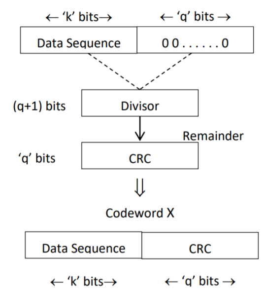
Fig 2 CRC Generation
- We divide the data sequence appended with 0s by the divisor. This is a binary division.
- The remainder obtained after the division is the ‘q’ bit CRC. Then, this ‘q’ bit CRC is appended to the data sequence. Actually, CRC is a sequence of redundant bits.
- The code word generated is now transmitted.
Q13) What is convolution code. Explain convolution encoder?
A13) In block coding, the encoder accepts a k-bit message block and generates an n-bit code word. Thus, code words are produced on a block-by-block basis. Therefore, a buffer is required in the encoder to place the message block. A subclass of Tree codes is convolutional codes. The convolutional encoder accepts the message bits continuously and generates the encoded codeword sequence continuously. Hence there is no need for buffer. But in convolutional codes, memory is required to implement the encoder.
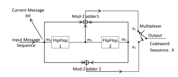
Fig 3. Convolutional Encoder
In a convolutional code, the encoding operation is the discrete-time convolution of the input data sequence with the impulse response of the encoder. The input message bits are stored in the fixed length shift register and they are combined with the help of mod-2 adders. This operation is equivalent to binary convolution and hence it is called convolutional coding. The figure above shows the connection diagram for an example convolutional encoder.
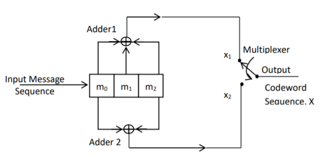
Fig 4. Convolutional Encoder redrawn alternatively
The encoder of a binary convolution code may be viewed as a finite-state machine. It consists of M-stage shift register with prescribed connections to modulo2 adders. A multiplexer serializes the outputs of the adders. The convolutional codes generated by these encoders of Figure above are non-systematic form. Consider that the current message bit is shifted to position m0. Then m1 and m2 store the previous two message bits. Now, by mod-2 adders 1 and 2 we get the new values of X1 and X2. We can write
X1 = m0 m1 m2 and
X2 = m0 m2
The multiplexer switch first samples X1 and then X2. Then next input bit is taken and stored in m0. The shift register then shifts the bit already in m0 to m1. The bit already in m1 is shifted to m2. The bit already in m2 is discarded. Again, X1 and X2 are generated according to this new combination of m0, m1 and m2. This process is repeated for each input message bit. Thus, the output bit stream for successive input bits will be,
X = x1 x2 x1 x2 x1 x2…….. And so on
In this convolutional encoder, for every input message bit, two encoded output bits X1 and X2 are transmitted. Hence number of message bits, k = 1. The number of encoded output bits for one message bit, n = 2.
Q14) Explain the state diagram representation of convolution code?
A14) State diagram representation
- The state of a convolutional encoder is defined by the contents of the shift register. The number of states is given by 2k-1 = 23-1 = 22 = 4. Here K represents the constraint length.
- Let the four states be A = 00, B = 10, C = 01 and D = 11 as per the logic table. A state diagram as shown in the figure below illustrates the functioning of the encoder.
- Suppose that the contents of the shift register is in the state A = 00. At this state, if the incoming message bit is 0, the encoder output is X = (x1 x2) = 00. Then if the m0, m1 and m2 bits are shifted, the contents of the shift register will also be in state A = 00. This is represented by a solid line path starting from A and ending at A itself.
- At the ‘A’ state, if the incoming message bit is 1, then the encoder output is X = 11. Now if the m0, m1 and m2 bits are shifted, the contents of the shift register will become the state B = 10. This is represented by a dashed line path starting from A and ending at B.
- Similarly, we can draw line paths for all other states, as shown in the Figure below.
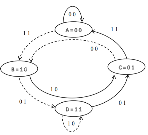
Fig 5. State Diagram
Q15) Explain the code tree representation of convolution code?
A15)
Code tree representation
- The code tree diagram is a simple way of describing the encoding procedure. By traversing the diagram from left to right, each tree branch depicts the encoder output codeword.
- Figure below shows the code representation for this encoder.
- The code tree diagram starts at state A =00. Each state now represents the node of a tree. If the input message bit is m0 = 0 at node A, then path of the tree goes upward towards node A and the encoder output is 00. Otherwise, if the input message bit is m0 = 1, the path of the tree goes down towards node B and the encoder output is 11.
- Similarly depending upon the input message bit, the path of the tree goes upward or downward. On the path between two nodes the outputs are shown.
- In the code tree, the branch pattern begins to repeat after third bit, since particular message bit is stored in the shift registers of the encoder for three shifts.
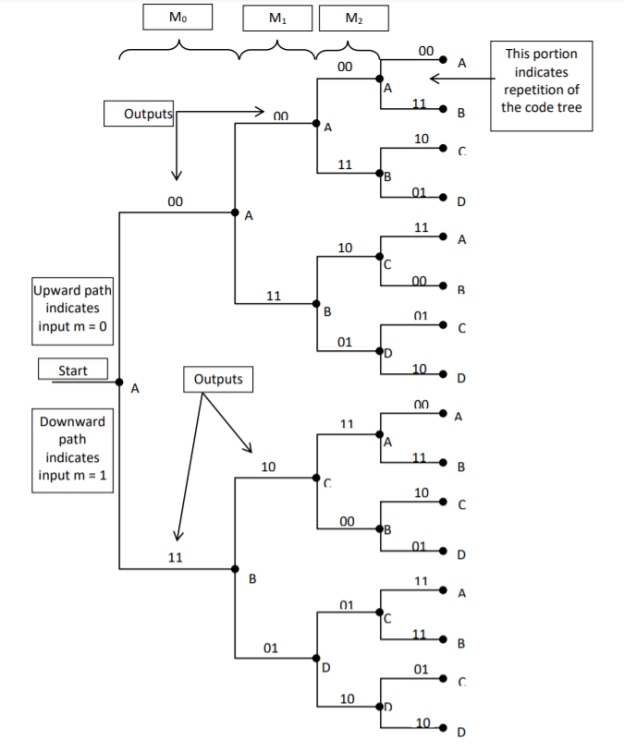
Fig 6. Code Tree Representation
Q16) Explain the code trellis representation of convolution code?
A16)
Code trellis representation
- Code trellis is the more compact representation of the code tree. In the code tree there are four states (or nodes). Every state goes to some other state depending upon the input message bit.
- Code trellis represents the single and unique diagram for such steady state transitions. The Figure below shows the code trellis diagram.
- The nodes on the left denote four possible current states and those on the right represents next state. The solid transition line represents for input message m0 = 0 and dashed line represents input message m0 = 1.
- Along with each transition line, the encoder output x1 x2 is represented during that transition.

Fig 7. Code Trellis
Q17) Compare Linear block codes and convolution codes?
A17)

Q18) Write short notes on turbo codes?
A18)
The use of a good code with random-like properties is basic to turbo coding. In the first successful implementation of turbo codes11, Berrouet al. Achieved this design objective by using concatenated codes. The original idea of concatenated codes was conceived by Forney (1966). To be more specific, concatenated codes can be of two types: parallel or serial. The type of concatenated codes used by Berrou et al. Was of the parallel type, which is discussed in this section

Fig 8. Block diagram of turbo encoder of the parallel type.
Figure above depicts the most basic form of a turbo code generator that consists of two constituent systematic encoders, which are concatenated by means of an interleaver. The interleaver is an input–output mapping device that permutes the ordering of a sequence of symbols from a fixed alphabet in a completely deterministic manner; that is, it takes the symbols at the input and produces identical symbols at the output but in a different temporal order. Turbo codes use a pseudo-random interleaver, which operates only on the systematic (i.e., message) bits. The size of the interleaver used in turbo codes is typically very large, on the order of several thousand bits. There are two reasons for the use of an interleaver in a turbo code:
1. The interleaver ties together errors that are easily made in one half of the turbo code to errors that are exceptionally unlikely to occur in the other half; this is indeed one reason why the turbo code performs better than a traditional code.
2. The interleaver provides robust performance with respect to mismatched decoding, a problem that arises when the channel statistics are not known or have been incorrectly specified.
Ordinarily, but not necessarily, the same code is used for both constituent encoders in Figure above. The constituent codes recommended for turbo codes are short constraint length RSC codes. The reason for making the convolutional codes recursive (i.e., feeding one or more of the tap outputs in the shift register back to the input) is to make the internal state of the shift register depend on past outputs. This affects the behavior of the error patterns, with the result that a better performance of the overall coding strategy is attained.
Q19) Explain two state turbo encoder in detail?
A19) Two-State Turbo Encoder Figure below shows the block diagram of a specific turbo encoder using an identical pair of two-state RSC constituent encoders. The generator matrix of each constituent encoder is given by
G(D)= (1, 1/1+D)
The input sequence of bits has length, made up of three message bits and one termination bit. The input vector is given by
m= m0 m1 m2 m3
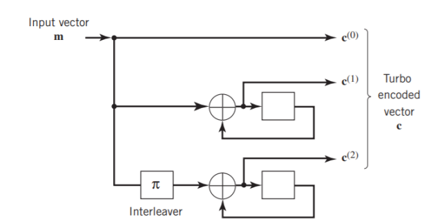
Fig 9. Two-state turbo encoder for Example
The parity-check vector produced by the first constituent encoder is given by
b(1) = (b0(1), b1(1), b2(1), b3(1))
Similarly, the parity – check produced by the second constituent encoder is given by
b(2)= (b0(2), b0(2), b0(2), b0(2))
The transmitted code vector is therefore defined by
c = (c(0), c(1), c(2))
With the convolutional code being systematic, we thus have
c(0) = m
As for the remaining two sub-vectors constituting the code vector c, they are defined by
c(1) = b(1)
And
c(2) = b(2)
The transmitted code vector c is therefore made up of 12 bits. However, recalling that the termination bit m3 is not a message bit, it follows that the code rate of the turbo code is
R=3/12=1/4
Q20) Explain the extrinsic form of turbo decoder?
A20) Figure (a) below shows the block diagram of the two-stage turbo decoder. The decoder operates on noisy versions of the systematic bits and the two sets of parity-check bits in two decoding stages to produce an estimate of the original message bits[5]. A distinctive feature of the turbo decoder that is immediately apparent from the block diagram of Figure(a) is the use of feedback, manifesting itself in producing extrinsic information from one decoder to the next in an iterative manner. In a way, this decoding process is analogous to the feedback of exhaust gases experienced in a turbo-charged engine; indeed, turbo codes derive their name from this analogy. In other words, the term “turbo” in turbo codes has more to do with the decoding rather than the encoding process. In operational terms, the turbo encoder in Figure11(a) operates on noisy versions of the following inputs, obtained by demultiplexing the channel output, rj
- Systematic (i.e., message) bits, denoted by rj(0)
- Parity-check bits corresponding to encoder 1 in Figure encoder, denoted by rj(1)
- Parity-check bits corresponding to encoder 2 in Figure encoder, denoted by rj(2)
The net result of the decoding algorithm, given the received vector rj, is an estimate of the original message vector, namely, which is delivered at the decoder output to the user. Another important point to note in the turbo decoder of Figure 11(a) is the way in which the interleaver and de-interleaver are positioned inside the feedback loop. Bearing in mind the fact that the definition of extrinsic information requires the use of intrinsic information, we see that decoder 1 operates on three inputs:
- The noisy systematic (i.e., original message) bits,
- The noisy parity-check bits due to encoder 1, and
- De-interleaved extrinsic information computed by decoder 2
(a)
(b)
Fig 10(a) Block diagram of turbo decoder. (b) Extrinsic form of turbo decoder, where I stand for interleaver, D for deinterleaver, and BCJR for BCJR for BCJR algorithm for log-MAP decoding [5].
In a complementary manner, decoder 2 operates on two inputs of its own:
- The noisy parity-check bits due to encoder 2 and
- The interleaved version of the extrinsic information computed by decoder 1.
- For this iterative exchange of information between the two decoders inside the feedback loop to continuously reinforce each other, the de-interleaver and interleaver would have to separate the two decoders in the manner depicted in Figure a. Moreover, the structure of the decoder in the receiver is configured to be consistent with the structure of the encoder in the transmitter.
Q21) Explain advantages of LDPC codes and explain the code in details?
A21)
The two most important advantages of LDPC codes over turbo codes are:
- Absence of low-weight codewords and
- Iterative decoding of lower complexity.
With regard to the issue of low-weight codewords, we usually find that a small number of codewords in a turbo codeword are undesirably close to the given codeword. Owing to this closeness in weights, once in a while the channel noise causes the transmitted codeword to be mistaken for a nearby code.
In contrast, LDPC codes can be easily constructed so that they do not have such low-weight codewords and they can, therefore, achieve vanishingly small BERs. Turning next to the issue of decoding complexity, we note that the computational complexity of a turbo decoder is dominated by the MAP algorithm, which operates on the trellis for representing the convolutional code used in the encoder. The number of computations in each recursion of the MAP algorithm scales linearly with the number of states in the trellis. Commonly used turbo codes employ trellises with 16 states or more. In contrast, LDPC codes use a simple parity-check trellis that has just two states. Consequently, the decoders for LDPC codes are significantly simpler to design than those for turbo decoders. However, a practical objection to the use of LDPC codes is that, for large block lengths, their encoding complexity is high compared with turbo codes. It can be argued that LDPC codes and turbo codes complement each other, giving the designer more flexibility in selecting the right code for extraordinary decoding performance.
Construction of LDPC Codes
LDPC codes are specified by a parity-check matrix denoted by A, which is purposely chosen to be sparse; that is, the code consists mainly of 0s and a small number of 1s. In particular, we speak of (n, tc, tr) LDPC codes, where n denotes the block length, tc denotes the weight (i.e., number of 1s) in each column of the matrix A, and tr denotes the weight of each row with tr >tc. The rate of such an LDPC code is defined by
r = 1 – tc/tr
Whose validity may be justified as follows. Let denote the density of 1s in the parity check matrix A.
tc = (n-k)
tr = n
Where (n – k) is the number of rows in A and n is the number of columns (i.e., the block length). Therefore, dividing tc by tr, we get
tc/tr = 1 – k/n
The structure of LDPC codes is well portrayed by bipartite graphs, which were introduced by Tanner (1981) and, therefore, are known as Tanner graphs. Figure below shows such a graph for the example code of n = 10, tc = 3, and tr = 5. The left-hand nodes in the graph are variable (symbol) nodes, which correspond to elements of the codeword. The right-hand nodes of the graph are check nodes, which correspond to the set of parity-check constraints satisfied by codewords in the code. LDPC codes of the type exemplified by the graph of Figure below are said to be regular, in that all the nodes of a similar kind have exactly the same degree. In Figure below, the degree of the variable nodes is tc = 3 and the degree of the check nodes is tr = 5. As the block length n approaches infinity, each check node is connected to a vanishingly small fraction of variable nodes; hence the term “low density.”
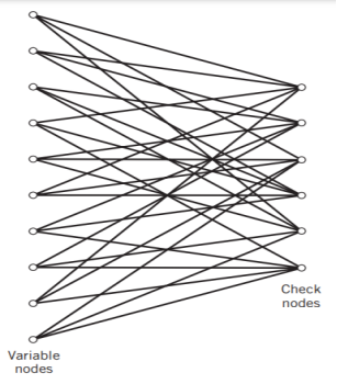
Fig 11. Bipartite graph of the (10, 3, 5) LDPC code [5]
The matrix A is constructed by putting 1s in A at random, subject to the regularity constraints:
- Each column of matrix A contains a small fixed number tc of 1s;
- Each row of the matrix contains a small fixed number tr of 1s.
In practice, these regularity constraints are often violated slightly in order to avoid having linearly dependent rows in the parity-check matrix A.
The parity-check matrix A of LDPC codes is not systematic (i.e., it does not have the parity-check bits appearing in diagonal form); hence the use of a symbol different from that used in Section 10.4. Nevertheless, for coding purposes, we may derive a generator matrix G for LDPC codes by means of Gaussian elimination performed in modulo-2 arithmetic. The 1-by-n code vector c is first partitioned as shown by
c = [ b | m]
Where m is the k-by-1 message vector and b is the (n – k)-by-1 parity-check vector. Correspondingly, the parity-check matrix A is partitioned as
AT = 
Where A1 is a square matrix of dimensions (n – k) (n – k) and A2 is a rectangular matrix of dimensions k (n – k); transposition symbolized by the superscript T is used in the partitioning of matrix A for convenience of presentation. Imposing a constraint on the LDPC code we may write
[b | m] = 0
= 0
BA1 + mA2 = 0
The vectors m and b are related by
b=mP
The coefficient matrix of LDPC codes satisfies the condition
PA1 + A2 = 0
For matrix P, we get
P =A2A1-1
The generator matrix of LDPC codes is defined by
G = [ P | Ik]
=[A2A1-1 | Ik]
Consider the Tanner graph pertaining to a (10, 3, 5) LDPC code. The parity-check matrix of the code is defined by
Which appears to be random, while maintaining the regularity constraints: tc = 3 and tr = 5. Partitioning the matrix A in the manner just described, we write
A1 = 
A2 = 
To derive the inverse of matrix A1
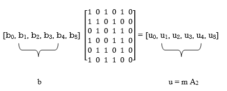
Where we have introduced the vector u to denote the matrix product mA2. By using Gaussian elimination, modulo-2, the matrix A1 is transformed into lower diagonal form (i.e., all the elements above the main diagonal are zero), as shown by
A1 
This transformation is achieved by the following modulo-2 additions performed on the columns of square matrix A1:
- Columns 1 and 2 are added to column 3;
- Column 2 is added to column 4;
- Columns 1 and 4 are added to column 5;
- Columns 1, 2, and 5 are added to column 6.
Correspondingly, the vector u is transformed as shown by
u [u0, u1, u0 + u1 + u2, u1 +u3, u0 + u3 + u4, u0 + u1 + u4 + u5]
Accordingly, pre multiplying the transformed matrix A1 by the parity vector b, using successive eliminations in modulo-2 arithmetic working backwards and putting the solutions for the elements of the parity vector b in terms of the elements of the vector u in matrix form, we get
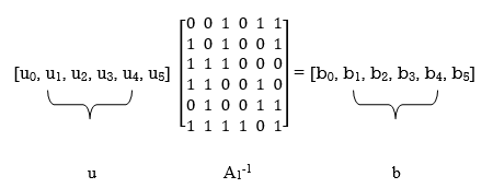
The inverse of matrix A1 is therefore
A1-1 = 
Using the given value of A2 and A1-1 the value of just found, the matrix product A2A1-1 is given by
A2A1-1 = 
LDPC code is defined by

Unit - 5
Channel Coding (PART-II)
Q1) The generator matrix for a block code is given below. Find all code vectors of this code
G = 
A1) The Generator matrix G is generally represented as
[G]kn =  kn
kn
 kn =
kn = 
On comparing,
The number of message bits, k = 3
The number of code word bits, n = 6
The number of check bits, q = n – k = 6 – 3 = 3
Hence, the code is a (6, 3) systematic linear block code. From the generator matrix, we have Identity matrix
Ikk = 
The coefficient or submatrix,
Pkq = 
Therefore, the check bits vector is given by,
[C]1q = [M]1k[P]kq
On substituting the matrix form,
[c1 c2 c3] = [m1 m2 m3]
From the matrix multiplication, we have
c1 = (1 m1) ⨁ (0 m2) ⨁ (1 m3)
c2 = (0 m1) ⨁ (1 m2) ⨁ (0 m3)
c3 = (0 m1) ⨁ (1 m2) ⨁ (1 m3)
On simplifying, we obtain
c1 = m1 ⨁ m3
c2 = m2
c3 = m2 ⨁ m3
Hence the check bits (c1 c2 c3) for each block of (m1 m2 m3) message bits can be determined.
(i) For the message block of (m1 m2 m3) = (0 0 0), we have
c1 = m1 ⨁ m3 = 0 ⨁ 0 = 0
c2 = m2 = 0
c3 = m2 ⨁ m3 = 0 ⨁ 0 = 0
(ii) For the message block of (m1 m2 m3) = (0 0 1), we have
c1 = m1 ⨁ m3 = 0 ⨁ 1 = 1
c2 = m2 = 0
c3 = m2 ⨁ m3 = 0 ⨁ 1 = 1
(iii) For the message block of (m1 m2 m3) = (0 1 0), we have
c1 = m1 ⨁ m3 = 0 ⨁ 0 = 0
c2 = m2 = 1
c3 = m2 ⨁ m3 = 1 ⨁ 0 = 1
Similarly, we can obtain check bits for other message blocks.
Q2) For a systematic (6,3) linear block code the parity matrix P is given by
P = 
- Find the possible code vector
- Draw the encoding circuit.
- Draw the syndrome calculation circuit for recorded vector
R = [r1 r2 r3 r4 r5 r6]
A2) Given n=6 and k=3 for (6,3) block code
Since k=3 there are 23 = 8 message vectors given by
(000),(001),(010),(011),(100),(101),(110),(111)
The code vector is found by
[C]= [D][G]
[G] = {Ik|P]= [I3|P]
1 0 0 | 1 0 1
0 1 0 |0 1 1
0 0 1|1 1 0
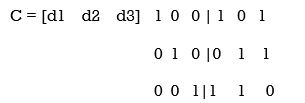
C= [d1,d2,d3,(d1+d3),(d2+d3),(d1+d2)]
Code name | Msg Vector | Code Vector For (6,3) liner block code |
| d 1 d 2 d3 | d 1 d 2 d 3 d 1+d 3 d2 + d3 d1 + d2 |
Ca | 0 0 0 | 0 0 0 0 0 0 |
Cb | 0 0 1 | 0 0 1 1 1 0 |
Cc | 0 1 0 | 0 1 0 0 1 1 |
Cd | 0 1 1 | 0 1 1 1 0 1 |
Ce | 1 0 0 | 1 0 0 1 0 1 |
Cf | 1 0 1 | 1 0 1 0 1 1 |
Cg | 1 1 0 | 1 1 0 1 1 0 |
Ch | 1 1 1 | 1 1 1 0 0 0 |
The code vector is given by
c 1 = d1 , c2 = d2 , c3 = d3 c4 = d1 + d3 c5 = d2 + d3 c6 = d1 + d2
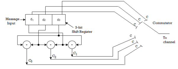
Since k=3 we require 3bit shift registers to move the message bits into it.
We have (n-k) = 6-3 = 3.
Hence we require 3-modulo 2 adders and 6 segement commutator.
For the (6,3) code matrix HT is given by
H T =
1 | 0 | 1 |
0 | 1 | 1 |
1 | 1 | 0 |
1 | 0 | 0 |
0 | 1 | 0 |
0 | 0 | 1 |
H T = [P/In-k] = [P/I3]
S= [s1 s2 s3] = [ r1 r2 r3 r4 r5 r6]
1 | 0 | 1 |
0 | 1 | 1 |
1 | 1 | 0 |
1 | 0 | 0 |
0 | 1 | 0 |
0 | 0 | 1 |
[S] = [S1 s2 s3] = (r1+r3+r4) , (r2+r3+r5),(r1+r2+r6)
S1 = r1+r3+r4
S2 = r2+r3+r5
S3 = r1 +r2 +r6
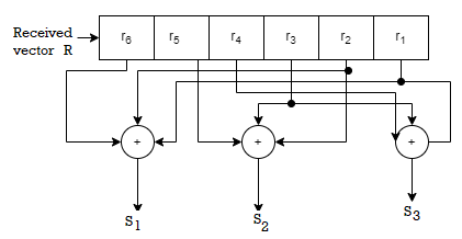
Fig 1 Syndrome calculation circuit
Q3) For a systematic (6,3) linear block code the parity marix P is given by
For the recorded code-vector R= [1 1 0 0 1 0] Detect and correct the single error that has occurred due to noise.
A3) Given

Parity check matrix [H] = [P T | I n-k] = [ PT | I3 ]
1 0 1 1 0 0
0 1 1 0 1 0
1 1 0 0 0 1
[S]= [100] since s≠0 it represents error. Since [100] present in the 4th row of HT . So the error vector [E] = [0 0 0 1 0 0 ] the the corrected vector is given by
C = R + E = [11 00 10][000100]
C = [110110] which is the valid code
Q4) The generator polynomial of a (7, 4) cyclic code is G(p) = p3 + p + 1. Find all the code vectors for the code in systematic form.
A4)
Here n = 7, k = 4
Therefore, q = n - k = 7 – 4 = 3
Since k = 4, there will be a total of 2k = 24 = 16 message vectors (From 0 0 0 0 to 1 1 1 1). Each can be coded into a 7 bits codeword.
(i) Consider any message vector as
M = (m3 m2 m1 m0) = (1 1 1 0)
By message polynomial,
M(p) = m3p3 + m2p2 + m1p + m0, for k = 4.
For the message vector (1 1 1 0), the polynomial is
M(p) = 1.p3 + 1.p2 + 1.p + 0.1
M(p) = p3 + p2 + p
The given generator polynomial is G(p) = p3 + p + 1
The check bits vector polynomial is

Thus, the remainder polynomial is p2 + 0.p + 0.1.
This is the check bits polynomial C(p)
c(p) = p2 + 0.p + 0.1
The check bits are c = (1 0 0)
Hence the code vector for the message vector (1 1 1 0) in systematic form is
X = (m3 m2 m1 m0⋮ c2 c1 c0) = (1 1 1 0 1 0 0)
(ii) Consider another message vector as
M = (m3 m2 m1 m0) = (1 0 1 0)
The message polynomial is M(p) = p3 + p
Then the check bits vector polynomial is

Thus, the check bits polynomial is C(p) = 0.p2 + 1.p + 1.1
The check bits are C = (0 1 1)
Hence the code vector is X= (1 0 1 0 0 1 1)
Similarly, we can find code vector for other message vectors also, using the same procedure.
Q5) Generate the CRC code for the data word of 1 1 1 0. The divisor polynomial is p3 + p + 1
A5)
Data Word (Message bits) = 1 1 1 0
Generator Polynomial (divisor) = p3 + p + 1
Divisor in binary form = 1 0 1 1
The divisor will be of (q + 1) bits long. Here the divisor is of 4 bits long. Hence q = 3. We append three 0s to the data word.
Now the data sequence is 1 1 1 0 0 0 0. We divide this data by the divisor of 1 0 1 1. Binary division is followed.
The remainder obtained from division is 100. Then the transmitted codeword is 1 1 1 0 1 0 0.
Q6) A codeword is received as 1 1 1 0 1 0 0. The generator (divisor) polynomial is p3 + p + 1. Check whether there is error in the received codeword.
A6)
Received Codeword = 1 1 1 0 1 0 0
Divisor in binary form = 1 0 1 1
We divide the received codeword by the divisor.
The remainder obtained from division is zero. Hence there is no error in the received codeword.
Q7) For the convolutional encoder given below in Figure, determine the following. a) Code rate b) Constraint length c) Dimension of the code d) Represent the encoder in graphical form.
A7)
a) Code rate:
The code rate, r = 𝑘/𝑛. The number of message bits, k = 1.
The number of encoder output bits, n = 2.
Hence code rate, r = 1/2
b) Constraint length:
Constraint length, k = 1 + number of shift registers.
Hence k = 1 + 2 = 3
c) Code dimension:
Code dimension = (n, k,K) = (2, 1, 3)
Hence the given encoder is of ½ rate convolutional encoder of dimension (2, 1, 3).
d) Graphical form representation
The encoder output is X = (x1 x2 x1 x2 x1 x2….. And so on)
The Mod-2 adder 1 output is x1 = m0 m1 m2
The Mod-2 adder 2 output is x2 = m0 m2.
We can represent the encoder output for possible input message bits in the form of a Logic table.

Output x1 = m0 m1 m2 and x2 = m0 m2
- The encoder output depends on the current input message bit and the contents in the shift register ie., the previous two bits.
- The present condition of the previous two bits in the shift register may be in four combinations. Let these combinations 00, 10, 01 and 11 be corresponds to the states A, B, C and D respectively.
- For each input message bit, the present state of the m1 and m2 bits will decide the encoded output.
- The logic table presents the encoded output x1 and x2 for the possible ‘0’ or ‘1’ bit input if the present state is A or B or C or D.
Q8) For given matrixes find standard array?
G =
0 | 1 | 1 | 1 | 0 | 0 |
1 | 0 | 1 | 0 | 1 | 0 |
1 | 1 | 0 | 0 | 0 | 1 |
H
1 | 0 | 0 | 0 | 1 | 1 |
0 | 1 | 0 | 1 | 0 | 1 |
0 | 0 | 1 | 1 | 1 | 0 |
A8)
The standard array has 6 coset leaders of weight 1 and weight 2.
000000 | 001110 | 010101 | 011011 | 100011 | 101101 | 110110 | 111000 |
000001 | 001111 | 010100 | 011010 | 100010 | 101100 | 110111 | 111001 |
000010 | 001100 | 010111 | 111001 | 100001 | 101111 | 110100 | 111010 |
000100 | 001010 | 010001 | 011111 | 100111 | 101001 | 110010 | 111011 |
001000 | 000110 | 011101 | 010011 | 101011 | 100101 | 111110 | 110000 |
010000 | 011110 | 000101 | 001011 | 110011 | 111101 | 100110 | 101000 |
100000 | 101110 | 110101 | 111011 | 000011 | 001101 | 010110 | 011000 |
001001 | 000111 | 011100 | 010010 | 101010 | 100100 | 111111 | 110001 |
Q9) How can we generate code vectors in systematic form of cyclic codes?
A9)
The code word for the systematic form of cyclic codes is given by
X = (k message bits ⋮q check bits)
X = (mk-1 mk-2 …….. m1 m0⋮ cq-1 cq-2….. c1 c0)
In polynomial form, the check bits vector can be written as
C(p) = cq-1pq-1 + cq-2pq-2 + …….. + c1p + c0
In systematic form, the check bits vector polynomial is obtained by
C(p) = rem [𝑝𝑞. 𝑀(𝑝)/𝐺(𝑝) ]
Where:
M(p) is message polynomial
G(p) is generating polynomial
‘rem’ is remainder of the division
Q10) How a code vector can be generated in non-systematic form of cyclic codes?
A10)
Let M = (mk-1, mk-2, …… m1, m0) be ‘k’ bits of message vector. Then it can be represented by the polynomial as,
M(p) = mk-1pk-1 + mk-2pk-2 + ……+ m1p + m0
The codeword polynomial X(P) is given as X (P) = M(P) . G(P)
Where G(P) is called as the generating polynomial of degree ‘q’ (parity or check bits q = n – k). The generating polynomial is given as G (P) = pq + gq-1pq-1+ …….. + g1p + 1
Here gq-1, gq-2….. g1 are the parity bits.
• If M1, M2, M3, …… etc. are the other message vectors, then the corresponding code vectors can be calculated as,
X1 (P) = M1 (P) G (P)
X2 (P) = M2 (P) G (P)
X3 (P) = M3 (P) G (P) and so on
All the above code vectors X1, X2, X3….. Are in non-systematic form and they satisfy cyclic property.
Q11) What are cyclic codes explain?
A11)
Binary cyclic codes are a subclass of the linear block codes. They have very good features which make them extremely useful. Cyclic codes can correct errors caused by bursts of noise that affect several successive bits. The very good block codes like the Hamming codes, BCH codes and Golay codes are also cyclic codes. A linear block code is called as cyclic code if every cyclic shift of the code vector produces another code vector. A cyclic code exhibits the following two properties.
(i) Linearity Property: A code is said to be linear if modulo-2 addition of any two code words will produce another valid codeword.
(ii) (ii) Cyclic Property: A code is said to be cyclic if every cyclic shift of a code word produces another valid code word. For example, consider the n-bit code word, X = (xn-1, xn-2, ….. x1, x0).
If we shift the above code word cyclically to left side by one bit, then the resultant code word is
X’ = (xn-2, xn-3, ….. x1, x0, xn-1)
Here X’ is also a valid code word. One more cyclic left shift produces another valid code vector X’’.
X’’ = (xn-3, xn-4, ….. x1, x0, xn-1, xn-2)
Representation of codewords by a polynomial
• The cyclic property suggests that we may treat the elements of a code word of length n as the coefficients of a polynomial of degree (n-1).
• Consider the n-bit code word, X = (xn-1, xn-2, ….. x1, x0)
This code word can be represented in the form of a code word polynomial as below:
X (p) = xn-1p n-1 + xn-2pn-2 + ….. + x1p + x0
Where X (p) is the polynomial of degree (n-1). p is an arbitrary real variable. For binary codes, the coefficients are 1s or 0s.
- The power of ‘p’ represents the positions of the code word bits. i.e., pn-1 represents MSB and p0 represents LSB.
- Each power of p in the polynomial X(p) represents a one-bit cyclic shift in time. Hence, multiplication of the polynomial X(p) by p may be viewed as a cyclic shift or rotation to the right, subject to the constraint that pn = 1.
- We represent cyclic codes by polynomial representation because of the following reasons.
1. These are algebraic codes. Hence algebraic operations such as addition, subtraction, multiplication, division, etc. becomes very simple.
2. Positions of the bits are represented with the help of powers of p in a polynomial.
Q12) Explain with the diagram CRC encoder?
A12) Cyclic codes are extremely well-suited for error detection. Because they can be designed to detect many combinations of likely errors. Also, the implementation of both encoding and error detecting circuits is practical. For these reasons, all the error detecting codes used in practice are of cyclic code type. Cyclic Redundancy Check (CRC) code is the most important cyclic code used for error detection in data networks & storage systems. CRC code is basically a systematic form of cyclic code.
CRC Generation (encoder)
The CRC generation procedure is shown in the figure below.
- Firstly, we append a string of ‘q’ number of 0s to the data sequence. For example, to generate CRC-6 code, we append 6 number of 0s to the data.
- We select a generator polynomial of (q+1) bits long to act as a divisor. The generator polynomials of three CRC codes have become international standards. They are
- CRC – 12 code: p12 + p11 + p3 + p2 + p + 1
- CRC – 16 code: p16 + p15 + p2 + 1
- CRC – CCITT Code: p16 + p12 + p5 + 1

Fig 2 CRC Generation
- We divide the data sequence appended with 0s by the divisor. This is a binary division.
- The remainder obtained after the division is the ‘q’ bit CRC. Then, this ‘q’ bit CRC is appended to the data sequence. Actually, CRC is a sequence of redundant bits.
- The code word generated is now transmitted.
Q13) What is convolution code. Explain convolution encoder?
A13) In block coding, the encoder accepts a k-bit message block and generates an n-bit code word. Thus, code words are produced on a block-by-block basis. Therefore, a buffer is required in the encoder to place the message block. A subclass of Tree codes is convolutional codes. The convolutional encoder accepts the message bits continuously and generates the encoded codeword sequence continuously. Hence there is no need for buffer. But in convolutional codes, memory is required to implement the encoder.
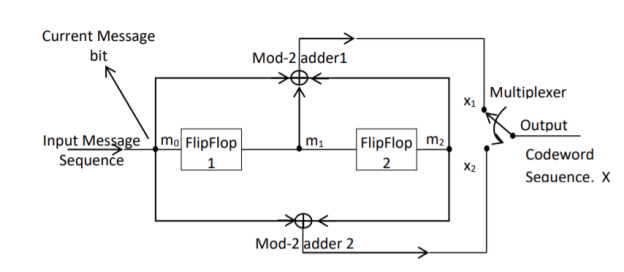
Fig 3. Convolutional Encoder
In a convolutional code, the encoding operation is the discrete-time convolution of the input data sequence with the impulse response of the encoder. The input message bits are stored in the fixed length shift register and they are combined with the help of mod-2 adders. This operation is equivalent to binary convolution and hence it is called convolutional coding. The figure above shows the connection diagram for an example convolutional encoder.
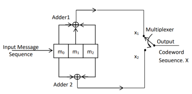
Fig 4. Convolutional Encoder redrawn alternatively
The encoder of a binary convolution code may be viewed as a finite-state machine. It consists of M-stage shift register with prescribed connections to modulo2 adders. A multiplexer serializes the outputs of the adders. The convolutional codes generated by these encoders of Figure above are non-systematic form. Consider that the current message bit is shifted to position m0. Then m1 and m2 store the previous two message bits. Now, by mod-2 adders 1 and 2 we get the new values of X1 and X2. We can write
X1 = m0 m1 m2 and
X2 = m0 m2
The multiplexer switch first samples X1 and then X2. Then next input bit is taken and stored in m0. The shift register then shifts the bit already in m0 to m1. The bit already in m1 is shifted to m2. The bit already in m2 is discarded. Again, X1 and X2 are generated according to this new combination of m0, m1 and m2. This process is repeated for each input message bit. Thus, the output bit stream for successive input bits will be,
X = x1 x2 x1 x2 x1 x2…….. And so on
In this convolutional encoder, for every input message bit, two encoded output bits X1 and X2 are transmitted. Hence number of message bits, k = 1. The number of encoded output bits for one message bit, n = 2.
Q14) Explain the state diagram representation of convolution code?
A14) State diagram representation
- The state of a convolutional encoder is defined by the contents of the shift register. The number of states is given by 2k-1 = 23-1 = 22 = 4. Here K represents the constraint length.
- Let the four states be A = 00, B = 10, C = 01 and D = 11 as per the logic table. A state diagram as shown in the figure below illustrates the functioning of the encoder.
- Suppose that the contents of the shift register is in the state A = 00. At this state, if the incoming message bit is 0, the encoder output is X = (x1 x2) = 00. Then if the m0, m1 and m2 bits are shifted, the contents of the shift register will also be in state A = 00. This is represented by a solid line path starting from A and ending at A itself.
- At the ‘A’ state, if the incoming message bit is 1, then the encoder output is X = 11. Now if the m0, m1 and m2 bits are shifted, the contents of the shift register will become the state B = 10. This is represented by a dashed line path starting from A and ending at B.
- Similarly, we can draw line paths for all other states, as shown in the Figure below.
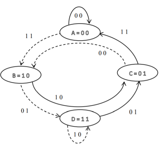
Fig 5. State Diagram
Q15) Explain the code tree representation of convolution code?
A15)
Code tree representation
- The code tree diagram is a simple way of describing the encoding procedure. By traversing the diagram from left to right, each tree branch depicts the encoder output codeword.
- Figure below shows the code representation for this encoder.
- The code tree diagram starts at state A =00. Each state now represents the node of a tree. If the input message bit is m0 = 0 at node A, then path of the tree goes upward towards node A and the encoder output is 00. Otherwise, if the input message bit is m0 = 1, the path of the tree goes down towards node B and the encoder output is 11.
- Similarly depending upon the input message bit, the path of the tree goes upward or downward. On the path between two nodes the outputs are shown.
- In the code tree, the branch pattern begins to repeat after third bit, since particular message bit is stored in the shift registers of the encoder for three shifts.
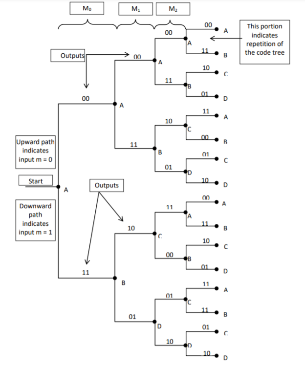
Fig 6. Code Tree Representation
Q16) Explain the code trellis representation of convolution code?
A16)
Code trellis representation
- Code trellis is the more compact representation of the code tree. In the code tree there are four states (or nodes). Every state goes to some other state depending upon the input message bit.
- Code trellis represents the single and unique diagram for such steady state transitions. The Figure below shows the code trellis diagram.
- The nodes on the left denote four possible current states and those on the right represents next state. The solid transition line represents for input message m0 = 0 and dashed line represents input message m0 = 1.
- Along with each transition line, the encoder output x1 x2 is represented during that transition.
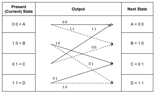
Fig 7. Code Trellis
Q17) Compare Linear block codes and convolution codes?
A17)

Q18) Write short notes on turbo codes?
A18)
The use of a good code with random-like properties is basic to turbo coding. In the first successful implementation of turbo codes11, Berrouet al. Achieved this design objective by using concatenated codes. The original idea of concatenated codes was conceived by Forney (1966). To be more specific, concatenated codes can be of two types: parallel or serial. The type of concatenated codes used by Berrou et al. Was of the parallel type, which is discussed in this section
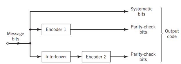
Fig 8. Block diagram of turbo encoder of the parallel type.
Figure above depicts the most basic form of a turbo code generator that consists of two constituent systematic encoders, which are concatenated by means of an interleaver. The interleaver is an input–output mapping device that permutes the ordering of a sequence of symbols from a fixed alphabet in a completely deterministic manner; that is, it takes the symbols at the input and produces identical symbols at the output but in a different temporal order. Turbo codes use a pseudo-random interleaver, which operates only on the systematic (i.e., message) bits. The size of the interleaver used in turbo codes is typically very large, on the order of several thousand bits. There are two reasons for the use of an interleaver in a turbo code:
1. The interleaver ties together errors that are easily made in one half of the turbo code to errors that are exceptionally unlikely to occur in the other half; this is indeed one reason why the turbo code performs better than a traditional code.
2. The interleaver provides robust performance with respect to mismatched decoding, a problem that arises when the channel statistics are not known or have been incorrectly specified.
Ordinarily, but not necessarily, the same code is used for both constituent encoders in Figure above. The constituent codes recommended for turbo codes are short constraint length RSC codes. The reason for making the convolutional codes recursive (i.e., feeding one or more of the tap outputs in the shift register back to the input) is to make the internal state of the shift register depend on past outputs. This affects the behavior of the error patterns, with the result that a better performance of the overall coding strategy is attained.
Q19) Explain two state turbo encoder in detail?
A19) Two-State Turbo Encoder Figure below shows the block diagram of a specific turbo encoder using an identical pair of two-state RSC constituent encoders. The generator matrix of each constituent encoder is given by
G(D)= (1, 1/1+D)
The input sequence of bits has length, made up of three message bits and one termination bit. The input vector is given by
m= m0 m1 m2 m3
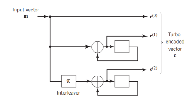
Fig 9. Two-state turbo encoder for Example
The parity-check vector produced by the first constituent encoder is given by
b(1) = (b0(1), b1(1), b2(1), b3(1))
Similarly, the parity – check produced by the second constituent encoder is given by
b(2)= (b0(2), b0(2), b0(2), b0(2))
The transmitted code vector is therefore defined by
c = (c(0), c(1), c(2))
With the convolutional code being systematic, we thus have
c(0) = m
As for the remaining two sub-vectors constituting the code vector c, they are defined by
c(1) = b(1)
And
c(2) = b(2)
The transmitted code vector c is therefore made up of 12 bits. However, recalling that the termination bit m3 is not a message bit, it follows that the code rate of the turbo code is
R=3/12=1/4
Q20) Explain the extrinsic form of turbo decoder?
A20) Figure (a) below shows the block diagram of the two-stage turbo decoder. The decoder operates on noisy versions of the systematic bits and the two sets of parity-check bits in two decoding stages to produce an estimate of the original message bits[5]. A distinctive feature of the turbo decoder that is immediately apparent from the block diagram of Figure(a) is the use of feedback, manifesting itself in producing extrinsic information from one decoder to the next in an iterative manner. In a way, this decoding process is analogous to the feedback of exhaust gases experienced in a turbo-charged engine; indeed, turbo codes derive their name from this analogy. In other words, the term “turbo” in turbo codes has more to do with the decoding rather than the encoding process. In operational terms, the turbo encoder in Figure11(a) operates on noisy versions of the following inputs, obtained by demultiplexing the channel output, rj
- Systematic (i.e., message) bits, denoted by rj(0)
- Parity-check bits corresponding to encoder 1 in Figure encoder, denoted by rj(1)
- Parity-check bits corresponding to encoder 2 in Figure encoder, denoted by rj(2)
The net result of the decoding algorithm, given the received vector rj, is an estimate of the original message vector, namely, which is delivered at the decoder output to the user. Another important point to note in the turbo decoder of Figure 11(a) is the way in which the interleaver and de-interleaver are positioned inside the feedback loop. Bearing in mind the fact that the definition of extrinsic information requires the use of intrinsic information, we see that decoder 1 operates on three inputs:
- The noisy systematic (i.e., original message) bits,
- The noisy parity-check bits due to encoder 1, and
- De-interleaved extrinsic information computed by decoder 2
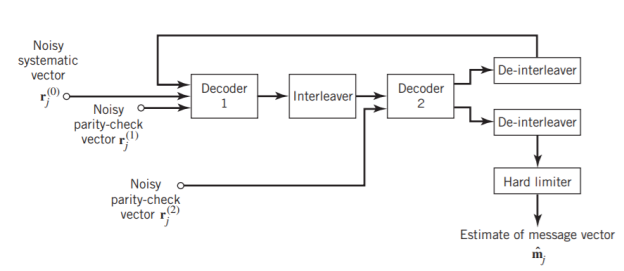
(a)

(b)
Fig 10(a) Block diagram of turbo decoder. (b) Extrinsic form of turbo decoder, where I stand for interleaver, D for deinterleaver, and BCJR for BCJR for BCJR algorithm for log-MAP decoding [5].
In a complementary manner, decoder 2 operates on two inputs of its own:
- The noisy parity-check bits due to encoder 2 and
- The interleaved version of the extrinsic information computed by decoder 1.
- For this iterative exchange of information between the two decoders inside the feedback loop to continuously reinforce each other, the de-interleaver and interleaver would have to separate the two decoders in the manner depicted in Figure a. Moreover, the structure of the decoder in the receiver is configured to be consistent with the structure of the encoder in the transmitter.
Q21) Explain advantages of LDPC codes and explain the code in details?
A21)
The two most important advantages of LDPC codes over turbo codes are:
- Absence of low-weight codewords and
- Iterative decoding of lower complexity.
With regard to the issue of low-weight codewords, we usually find that a small number of codewords in a turbo codeword are undesirably close to the given codeword. Owing to this closeness in weights, once in a while the channel noise causes the transmitted codeword to be mistaken for a nearby code.
In contrast, LDPC codes can be easily constructed so that they do not have such low-weight codewords and they can, therefore, achieve vanishingly small BERs. Turning next to the issue of decoding complexity, we note that the computational complexity of a turbo decoder is dominated by the MAP algorithm, which operates on the trellis for representing the convolutional code used in the encoder. The number of computations in each recursion of the MAP algorithm scales linearly with the number of states in the trellis. Commonly used turbo codes employ trellises with 16 states or more. In contrast, LDPC codes use a simple parity-check trellis that has just two states. Consequently, the decoders for LDPC codes are significantly simpler to design than those for turbo decoders. However, a practical objection to the use of LDPC codes is that, for large block lengths, their encoding complexity is high compared with turbo codes. It can be argued that LDPC codes and turbo codes complement each other, giving the designer more flexibility in selecting the right code for extraordinary decoding performance.
Construction of LDPC Codes
LDPC codes are specified by a parity-check matrix denoted by A, which is purposely chosen to be sparse; that is, the code consists mainly of 0s and a small number of 1s. In particular, we speak of (n, tc, tr) LDPC codes, where n denotes the block length, tc denotes the weight (i.e., number of 1s) in each column of the matrix A, and tr denotes the weight of each row with tr >tc. The rate of such an LDPC code is defined by
r = 1 – tc/tr
Whose validity may be justified as follows. Let denote the density of 1s in the parity check matrix A.
tc = (n-k)
tr = n
Where (n – k) is the number of rows in A and n is the number of columns (i.e., the block length). Therefore, dividing tc by tr, we get
tc/tr = 1 – k/n
The structure of LDPC codes is well portrayed by bipartite graphs, which were introduced by Tanner (1981) and, therefore, are known as Tanner graphs. Figure below shows such a graph for the example code of n = 10, tc = 3, and tr = 5. The left-hand nodes in the graph are variable (symbol) nodes, which correspond to elements of the codeword. The right-hand nodes of the graph are check nodes, which correspond to the set of parity-check constraints satisfied by codewords in the code. LDPC codes of the type exemplified by the graph of Figure below are said to be regular, in that all the nodes of a similar kind have exactly the same degree. In Figure below, the degree of the variable nodes is tc = 3 and the degree of the check nodes is tr = 5. As the block length n approaches infinity, each check node is connected to a vanishingly small fraction of variable nodes; hence the term “low density.”
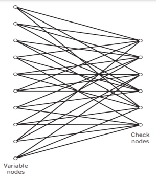
Fig 11. Bipartite graph of the (10, 3, 5) LDPC code [5]
The matrix A is constructed by putting 1s in A at random, subject to the regularity constraints:
- Each column of matrix A contains a small fixed number tc of 1s;
- Each row of the matrix contains a small fixed number tr of 1s.
In practice, these regularity constraints are often violated slightly in order to avoid having linearly dependent rows in the parity-check matrix A.
The parity-check matrix A of LDPC codes is not systematic (i.e., it does not have the parity-check bits appearing in diagonal form); hence the use of a symbol different from that used in Section 10.4. Nevertheless, for coding purposes, we may derive a generator matrix G for LDPC codes by means of Gaussian elimination performed in modulo-2 arithmetic. The 1-by-n code vector c is first partitioned as shown by
c = [ b | m]
Where m is the k-by-1 message vector and b is the (n – k)-by-1 parity-check vector. Correspondingly, the parity-check matrix A is partitioned as
AT = 
Where A1 is a square matrix of dimensions (n – k) (n – k) and A2 is a rectangular matrix of dimensions k (n – k); transposition symbolized by the superscript T is used in the partitioning of matrix A for convenience of presentation. Imposing a constraint on the LDPC code we may write
[b | m] = 0
= 0
BA1 + mA2 = 0
The vectors m and b are related by
b=mP
The coefficient matrix of LDPC codes satisfies the condition
PA1 + A2 = 0
For matrix P, we get
P =A2A1-1
The generator matrix of LDPC codes is defined by
G = [ P | Ik]
=[A2A1-1 | Ik]
Consider the Tanner graph pertaining to a (10, 3, 5) LDPC code. The parity-check matrix of the code is defined by
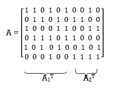
Which appears to be random, while maintaining the regularity constraints: tc = 3 and tr = 5. Partitioning the matrix A in the manner just described, we write
A1 = 
A2 = 
To derive the inverse of matrix A1

Where we have introduced the vector u to denote the matrix product mA2. By using Gaussian elimination, modulo-2, the matrix A1 is transformed into lower diagonal form (i.e., all the elements above the main diagonal are zero), as shown by
A1 
This transformation is achieved by the following modulo-2 additions performed on the columns of square matrix A1:
- Columns 1 and 2 are added to column 3;
- Column 2 is added to column 4;
- Columns 1 and 4 are added to column 5;
- Columns 1, 2, and 5 are added to column 6.
Correspondingly, the vector u is transformed as shown by
u [u0, u1, u0 + u1 + u2, u1 +u3, u0 + u3 + u4, u0 + u1 + u4 + u5]
Accordingly, pre multiplying the transformed matrix A1 by the parity vector b, using successive eliminations in modulo-2 arithmetic working backwards and putting the solutions for the elements of the parity vector b in terms of the elements of the vector u in matrix form, we get
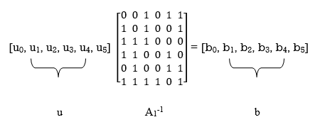
The inverse of matrix A1 is therefore
A1-1 = 
Using the given value of A2 and A1-1 the value of just found, the matrix product A2A1-1 is given by
A2A1-1 = 
LDPC code is defined by
