Unit - 5
Hydrodynamic pumps
Q1) What is centrifugal pump?
A1)
Hydraulic machine that converts the mechanical energy into hydraulic energy / pressure are called pumps. If the mechanical energy is converted into pressure energy by means of centrifugal force acting on the fluid, the hydraulic machine is called centrifugal pump.
It acts as a reverse of an inward radial flow reaction turbine. Flow is in the radial outward direction.
Works on the principle of forced vortex flow, when a certain mass of liquid is rotated by an external torque, the rise in pressure head of the rotating liquid takes place.
Rise in pressure head 
At the outlet of the impeller, the rise in pressure head will be more due to which the liquid can be lifted to a higher level.
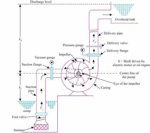
Fig.: Centrifugal pump
Q2) Explain work done by the centrifugal pump (impeller) on water
A2)
Work is done by impeller on water. The water enters the impeller radially at inlet for best efficiency of the pump.
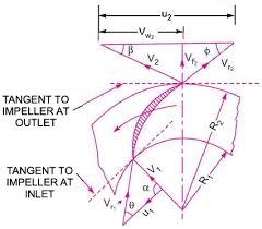
Fig: Work done by the centrifugal pump (impeller) on water
The absolute velocity of water at inlet makes an angle 900 with the direction of motion of the impeller at inlet.
= 90 and Vw1 = 0
Let,
N = Speed of impeller in RPM
D1 = Diameter of impeller at inlet
U1 = Tangential velocity of impeller at inlet = 
D2 = Diameter of impeller at outlet
U2 = Tangential velocity of impeller at outlet = 
V1 = Absolute velocity of water at inlet
Vr1 = Relative velocity of water at inlet
= Angle made by relative velocity (V1) at inlet with the direction of motion of vane.
= Angle made by relative velocity (Vr1) at inlet with the direction of motion of vain.
V2, , Corresponding values at outlet
When water enters, = 90 and Vw1 = 0
Centrifugal pump is reverse of radically inward flow turbine.
The work done by water on a runner per second per unit weight of the water is striking per second is given by (for turbine).
=  Vw1 U1 - Vw2 U2)
Work done by impeller on water per second =  Vw2 U2
W = weight of water = gQ
Q = AV = πD1B1 Vf1
Q = πd2B2 Vf2
Q = Volume of water
B1& B2 are width of impeller at inlet & outlet
Q3) Give Classification of Centrifugal pumps
A3)
- According to the types of stages:
Single stage pumps:
- It is known as single impeller pump.
- It is simple in design and easy in maintenance.
- It is ideal for large flow rates and low pressure installations.
Two stage pump:
- It has two impellers operating side by side.
- It is used for medium use applications.
Multistage Pumps:
- It has three or more impellers in series.
- They are used for high head applications.
- According to the type of case – split:
Axial split:
- In these types of pumps the volute casing is split axially and split line at which the pump casing separates is at the shaft’s centre – line.
Radial split:
- In it pump case is split radially, the volute casing split is perpendicular to shaft centre line.
- According to the types of impeller design.
Single suction:
- It has single suction impeller which allows fluid to enter blades only through a single opening.
Double Suction:
- It has double suction impeller which allows fluid to enter from both the sides of blades.
- They are most common types of pumps.
- According to the type of volute:
Single volute pump:
- It is usually used for low capacity pumps, as it has small volute size.
Double volute pump:
- It has two volutes which are placed 180 degrees apart.
- It has a good capability of balancing radial loads.
- According to the shaft orientation:
Horizontal Centrifugal pumps:
- It is suitable for low pressure.
Vertical Centrifugal pumps:
- It can easily withstand higher pressure loads.
- It is more expensive than horizontal pumps.
Q4) What are Component of Centrifugal Pump?
A4)
1. Impeller
- The rotating part of a centrifugal pump is called impeller it consists of a series of a backward curved vanes.
- The impeller is mounted on a shaft which is connected to the shaft of an electric motor.
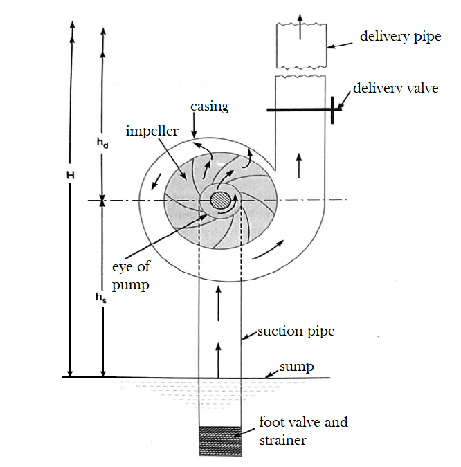
2. Casing
- It is an airtight passage surrounding the impeller and is designed in such a way that the kinetic energy of the water discharge at the outlet of the impulse is converted into pressure energy before the bottle leaves the casing and enters the delivery pipe.
- The following three types of the casings are commonly adopted
a) Volute casing:
- Above Figure shows the volute casing which surrounds the impeller.
- It is of spiral type in which area of flow increases gradually.
- The increase in area of flow decreases the velocity of flow.
- The decrease in velocity increases the pressure of the water flowing through the casing.
b) Vortex casing
- If a circular chamber is introduced between the casing and impeller as shown in figure, the casing is known as vortex casing.
- By introducing the circular chamber, the loss of energy due to the formation of eddies is reduced to a considerable extent.
- Also the liquid from the impeller has first to pass through the circular chamber in which the liquid is having free vortex flow.
- Hence velocity of liquid reduces while flowing through circular chamber. The decrease in velocity increases pressure.
- Thus the efficiency of the pump is more than the efficiency when only volute casing is provided.
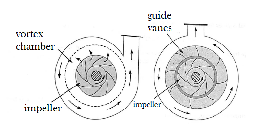
Fig. Vortex Casing Casing with Guide Blades
c) Casing with guide blades or turbine pump
- This casing is shown in figure in which the impeller is surrounded by a series of guide blades mounted on a ring which is known as diffuser.
- The guide vanes are designed in such a way that the water from the imperial enters the guide vanes without stock.
- Also the area of the guide vanes increases does reducing the velocity of flow through guide vanes and consequently increasing the pressure of water.
- The water from the guide vanes then passes through the surrounding casing which is in most of the cases concentric with the impeller as shown in figure
- Casing with guide blades is more efficient because of gradually reduction in velocity through guide blades.
3. Suction pipe with a foot valve and strainer
- A pipe whose one end is connected to the inlet of the pump and other and end dips into water in a sump is known as suction pipe.
- A foot valve which is non return valve or one way type of valve is fitted at the lower end of the suction pipe. The foot valve opens in the upward direction.
- A strainer is also fitted at the lower end of the suction pipe.
4. Delivery pipe
- A pipe whose one end is connected to the outlet of the pump and other and deliver the water at required height is known as delivery pipe.
Q5) Explain various heads in centrifugal pump.
A5)
Various heads
1. Suction head (hs)
It is the vertical height of the centerline of the centrifugal pump above the water surface in the tank from which water is to be lifted. This is also called suction lift and is denoted by hs.
2. Delivery head (hd)
The vertical between the centre line of the pump and the water surface in the tank to which water is delivered is known as delivery head. This is denoted by hd.
3. Static head (Hs)
The sum of suction head and delivery head is known as static head.
This is represented byHsand is written as
Hs = hs+ hd
4. Manometric head (Hm)
The manometric head is defined as the head against which a centrifugal pump has to work. It is denoted by Hm
Hm = Head imparted by the impeller – Loss of head in the pump to the water
=  - Loss of head in the impeller and casing
=  if loss of pump is zero.
Head imported by the impeller- loss of head in the pump to the water
Head in the impeller and casing
If loss of pump is zero
Hm = Total head at the outlet of pump-total head at the inlet of pump
Hm = 
 = Pressure head at outlet of pump
 = Velocity head at outlet of pump
 = Velocity head in delivery pipe
Zo Vertical height of the outlet of pump from datum line
Hm = hs+ hd+ hfs+ hfd+ 
hfs = Frictional head loss in suction pipe
hfd = Frictional head loss in delivery pipe
Vd = Velocity of water in delivery pipe
Q6) Explain Velocity triangles and their analysis
A6)
- In case of the centrifugal pump, work is done by the impeller on the water.
- The expression for the work done by the impeller on the water is obtained by drawing velocity triangles at inlet and outlet of the impeller.
- The water enters the impeller radially at inlet for best efficiency of the pump, which means the absolute velocity of water at inlet makes an angle of 90° with the direction of motion of the impeller at inlet. Hence angle
= 90˚
And
Vw1 = 0
- Figure shows the velocity triangles at the inlet and outlet tips of the vanes fixed to an impeller,
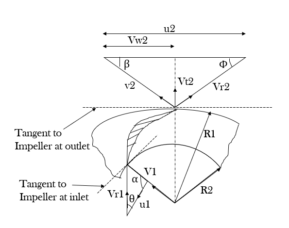
Let, N= speed of the impeller in r.p.m
D1 = Diameter of impeller at inlet
u1 = Tangential velocity of impeller at inlet= 
D2 = Diameter of impeller at Outlet
u12 = Tangential velocity of impeller at outlet= 
V1 = Absolute velocity of water at inlet
Vr1 = Relative velocity of water at inlet
= Angle made by absolute velocity (V1)at inlet with the direction of motion of vane
= Angle made by relative velocity (Vr1) at inlet with the direction of motion of vane and V2, Vr2, & are the corresponding values at outlet.
A centrifugal pump is the reverse of a radially inward flow reaction turbine. But in case of radially inward flow reaction turbine, the work done by the water on the runner per second per unit weight of water striking per second is given by equation
1/g [Vw1 u1 – Vw2 u2]
Work done by the impeller on the water per second per unit weight of water striking per second = - [work done in case of turbine]
= - [1/g (Vw1 – Vw2) = 1/g [Vw2 u2 – Vw1 u1]
= 1/g vw2 u2 (as Vw1 = 0)
Work done by impeller on water per second
= W/g vw2 u2
Where W = weight of water= ×g×Q
Where Q= Volume of water
And, Q= Area × velocity of flow = πD1 B1 × Vf1 = πD2 B2 × Vf2 ................( 19.2 A)
Where B1 and B2are width of impeller at inlet and outlet andVf1 and Vf2 velocity of flow at inlet and outlet
Q7) What is NPSH?
A7)
Net Positive Suction Head (NPSH)
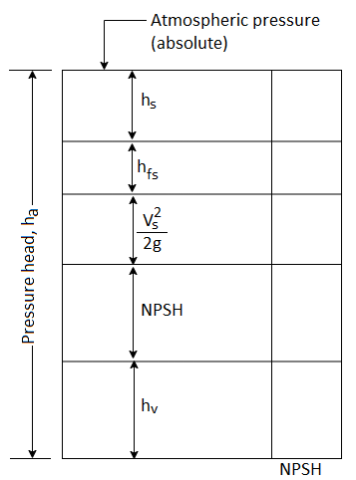
The net positive suction head (NPSH) is defined as the absolute pressure head at the inlet to the pump to force the liquid into the pump at a given temperature.
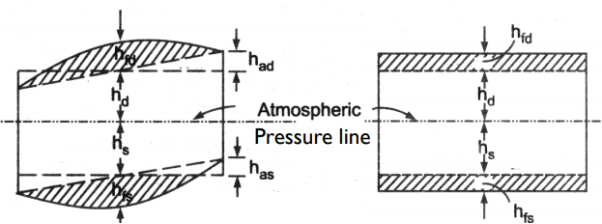
Fig. Shows how the pressure at the eye of impeller falls below the atmospheric pressure.
It is necessary that NPSH into the eye of impeller.
NPSH =  +
+ 
Therefore,
NPSH = ha – ( hv + 
The value of NPSH is mainly affected by the temperature of liquid to be handled by the pump since hv and hfs are the function of temperature
NPSH (Required)
Required NPSH is based on the pump design and its speed and capacity. It is then tested to determine the NPSH at de pomp gives the maximum efficiency. Accordingly, the value of NPSH required is specified by the manufacturer of mp It presents the minimum value of NPSH to avoid cavitation at specified discharge and speed.
NPSH (Available)
Available NPSH of the pump is estimated after installation of pump which is based on the suction pipe diameter, liquid be handled and temperatures of operation (both the place of installation and the liquid temperature), length of suction pipe a coefficient of friction and flow rates. While estimating this NPSH, the diameter of suction pipe must be same as per acturer's design specifications.
In order to have cavitation free operation of pump the available NPSH must be greater than the required NPSH. NPSH available must be higher than NPSH required.
Q8) Explain Cavitation in centrifugal pump.
A8)
Cavitation is defined as the phenomenon of formation of vapour bubbles in the region of flowing liquid where its pressure falls below the vapour pressure of liquid, then the liquid will vaporize and flow will no longer will be continuous.
When these vapour bubbles travel into the region of higher pressure, they suddenly collapse on the metallic surfaces and the surrounding liquid rushes to fill the cavities of vapour bubbles. The severe rush of liquid causes the development of extremely high pressures
Prolonged cavitation causes erosion and putting of metals, severn vibrations and noise. Fig. Shows the suction side of pump. Consider two points A and B at inlet to eye of impeller and on the sump level respectively.
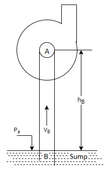
Let,
Pa = absolute atmospheric pressure.
Ps= absolute pressure at eye of impeller
Hs = suction lift
Vs = velocity in suction pipe
Hfs = friction losses in suction pipe
By Bernoulli’s theorem
 +
+ 


Therefore, the absolute pressure at inlet to eye of impeller falls below that of atmospheric pressure
Q9) Explain estimation of Maximum Permissible Suction Lift (Limited by Cavitation)
A9)
As discussed above, the cavitation occurs when the pressure at inlet to impeller falls below the vapour pressure liquid, p. Therefore, to avoid cavitation the condition is that

Therefore, the limiting value of absolute suction pressure at inlet to impeller is p, P. On substituting this value a
Equation the maximum permissible suction lift, h, can be estimated as follows

Permissible suction lift,

Note: The vapour pressure of liquid increases with the increase in temperature.
Q10) What are performance characteristics of centrifugal pump?
A10)
A centrifugal pump is designed to develop certain manometric head and discharge at constant speed since the pumps are usually driven by A.C. Motors. In certain cases, the pumps may be driven by an I.C. Engine at variable speed or the pump in actual practice may needed to develop a certain head or discharge. Under these actual conditions, the behaviour of the pump will be different than expected. Therefore, various tests on the pump under variable conditions are conducted in order to predict the behaviour and performance of the pump. The test results are then plotted on a graph under different flow rates, head and speed.
The curves thus obtained are known as characteristic curves for the pump.
Types of Performance Characteristic Curves
The performance characteristic curves are broadly divided into following four categories:
1. Main characteristic curves.
2. Operating characteristic curves.
3. Iso-efficiency or Muschel curves.
4. Constant head and constant discharge curves.
Q11) What are the types of performance characteristics?
A11)
1. Main Characteristic Curves
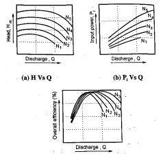
Main characteristic curves are obtained by test run at constant speed and the discharge is varied by means of delivery valve.
At each discharge, the manometric head Hm and input power P are measured and the overall efficiency ηo is calculated. Test curves are plotted between Hm vs Q, P vs Q and ηo Vs Q as shown in figure for that constant speed. The test run is repeated by running the pump at another constant speed. A family of curves will be obtained a various constant speed N1, N2 .... As shown in Fig.
2. Operating characteristic curves
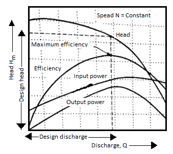
The pumps are designed for maximum, efficiency at a given speed called designed speed. Therefore, the pumps are test run at designed speed as provided by the manufacturer of the pump. The discharge is varied as discussed in case of main characteristic curve and the head and power input are measured. The overall efficiency of the pump is calculated. The performance curve thus obtained at design speed are called operating characteristic curve at shown in figure.
3. Iso-efficiency or Muschel curves
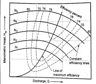
Iso-efficiency i.e. constant efficiency curves are useful in predicting the performance on entire operations and its best performance.
These characteristic curves can be drawn with the help of ηo Vs Q and Hm vs Q curves shown in figure in previous part. The method is as follows:
- Draw a horizontal line on ηo Vs Q curve. It represents the constant efficiency line.
- The points at which the constant efficiency line cuts the constant speed lines, the discharges are noted.
- At a given discharge and speed, the Hm is noted from Hm vs Q graph.
- These values of Hm and Q at constant efficiency and speed are projected on a graph of Hm vs Q as shown below.
- The points corresponding to same overall efficiency are joined with smooth curve. These curves represent the iso efficiency curves.
4. Constant head and constant discharge curves
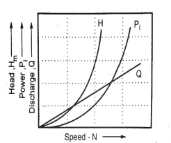
Pumps do not always operate at designed speed and conditions. So, it is necessary to compute performance of pump under various conditions to predict the performance. For these curves, delivery valve opening is fixed and kept constant during the test on pump. Then it is operated at variable speed and characteristics are plotted as shown below.
Q12) What is self priming pump?
A12)
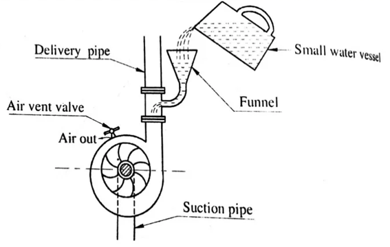
- Priming of centrifugal pump is defined as the operation in which the suction pipe, casing of the pump and a portion of the delivery pipe up to the delivery valve is completely filled up from outside source with liquid to be raised by the pump before starting the pump.
- Thus the air from these parts of the pump is removed and these parts are filled with the liquid to be pumped.
- The work done by the impulse per unit weight of liquid per second is known as the head generated by the pump.
- Equation gives the head generated by the pump as =
 metre.
 - This equation is independent of the density of the liquid.
- This means that when pump is running in air the head generated is in terms of metre of air.
- If the pump is primed with water, the head generated is same metre of water.
- But as the density of air is very low, the generated head of air in terms of equivalent metre of water head is negligible and hence the water may not be sucked from the pump.
- To avoid this difficulty priming is necessary.
- The pumps can be primed by any of the following method
- Manually
- In this method water is poured in the pump through funnel.
- When priming is being done, an air escapes through air vent valve.
Q13) Give Reciprocating pump: Basic principle.
A13)
Definition
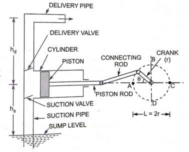
The Reciprocating Pump is a Positive Displacement type pump that works on the basis of piston movement in forward and backward directions. When a specified amount of fluid (usually sump) needs to be carried from the lowest to the highest location by applying pressure, reciprocating pumps are used. It is used in various industries including Gas industries, Petrochemical industries, Oil refineries
Diagram
Q14) Give Working, advantages and disadvantages of reciprocating pump.
A14)
The reciprocating pump's crank rotates through an electric motor when voltage is provided. The movement of the piston inside the cylinder is controlled by the angle created by the crank. When the crank reaches position A, i.e.=0, the piston advances to the extreme left of the cylinder, as shown in the diagram. Similarly, when the crank reaches position C, i.e. 180, the piston advances to the extreme right of the cylinder. When the piston is moved to the right extreme position (=0 to=180), a partial vacuum is created in the cylinder, allowing the liquid to enter the suction pipe. This is due to the reason that the sump liquid is subjected to atmospheric pressure, which is much lower than the pressure inside the cylinder. As a result of the pressure difference, water enters the cylinder through a non-return valve. The water that remains in the cylinder volume must be discharged to the discharge pipe via the discharge valve, which can be done when the crank rotates from C to A, i.e. (=180 to=360), moving the piston forward. The pressure inside the cylinder rises due to the forward movement of the piston, which is larger than the ambient pressure. The delivery valve opens and the suction valve closes as a result of this. The water cannot return to the cylinder once it enters the delivery valve since it is a non-return valve. It then enters the delivery pipe, where it is delivered to the desired location.
Advantages
- Unlike centrifugal pumps, the reciprocating pump does not require priming.
- It can transfer liquid from the sump to the desired height at high pressure.
Disadvantages
- Because there are so many pieces, the maintenance costs are extremely high.
- This pump has a high initial cost.
- The flow rate is lower.
- Pumping viscous fluids is tough.
Q15) Give the classification of reciprocating pump?
A15)
Based on Cylinder type:
- Single Acting
- Double Acting
The pump is called a single acting pump if the water only comes into contact with one side of the piston, and a double acting pump if the water comes into contact with both sides of the piston.
Based on No. Of Cylinder
- Single Cylinder
- Double Cylinder
- Multi-Cylinder
A single cylinder pump is a reciprocating pump with only one cylinder. It could be a single-action or a double-action pump. Multi-cylinder pumps are those that have more than one cylinder. Two pumps, three pumps, three throw pumps
The following are commonly known types of reciprocating pumps:
- Single-acting reciprocating pump: This has one suction valve and one discharge valve. When the piston is moved backward, suction happens and when it moves forward, the delivery valve opens up to discharge the liquid.
- Double-acting reciprocating pump: Unlike single acting pump, here there are two suction and delivery valves. When the piston is moved forward or backward, with each stroke, both suction and expulsion happen simultaneously. Thus, it requires two inflow pipes and two outflow pipes. Some of the common applications of these kinds of pumps are in Salt Water Disposal, Well Service, Descaling, Hydraulic Fracturing, and Oil & Gas Pipelines.
- Double acting – Air and Steam pumps: These are double acting pumps where steam, air or gas is used to transmit power to the liquid through the piston. The ratio of total steam force (steam pressure per unit area x area of the steam piston) to total liquid force (pump head x area of the liquid piston) helps determine the efficiency with which the pump produces pressure. They can operate at any point of pressure and flow, within a flexible range. Because of these features, steam driven pumps are mostly used in the refineries for pump-out service, with low NPSH and the fluids used are hydrocarbons mostly with high viscosity and high temperature.
- Simplex, Duplex, triplex, Quintuplex Pumps: Many reciprocating type pumps are simplex(one), duplex (two) or triplex (three) cylinder. Duplex pumps are usually used where the two pumps can be used alternatively. Such pumps are commonly used in oil-line pumping, mine de-watering, and chemical and petroleum products transfer, but has many more applications. A triplex pump consists of three plungers, with the aim of reducing the pulsation of a single reciprocating pump. Quintuple pumps are designed with a gear case that assists in a high-pressure task. Common applications of which are in cement slurries, sand-laden fluids, crude oil, acids, mud and other oil well-servicing fluids.
- Metering Pumps: A metering pump is usually used where the rate of flow of the liquid needs to be adjusted in a specific time period. Most of the metering pumps are piston driven and are called Piston pumps. Piston pumps can pump at a constant flow rate against any kind of discharge pressure. Both Piston pumps and Plunger pumps are reciprocating positive displacement pumps that use a plunger or piston to move fluid/substance through a cylindrical chamber.
Q16) What are the component of reciprocating pump?
A16)
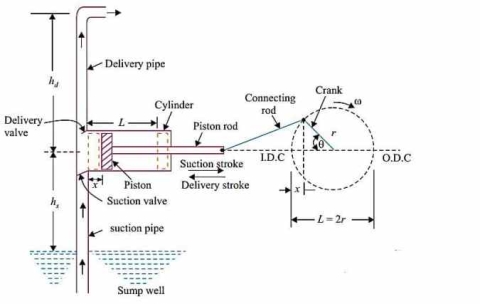
The main components of reciprocating pump are as follows:
- Suction Pipe
- Suction Valve
- Delivery Pipe
- Delivery Valve
- Cylinder
- Piston and Piston Rod
- Crank and Connecting Rod
- Strainer
- Air Vessel
1. Suction Pipe
Suction pipe connects the source of liquid to the cylinder of the reciprocating pump. The liquid is suck by this pipe from the source to the cylinder.
2. Suction Valve
Suction valve is non-return valve which means only one directional flow is possible in this type of valve. This is placed between suction pipe inlet and cylinder. During suction of liquid it is opened and during discharge it is closed.
3. Delivery Pipe
Delivery pipe connects cylinder of pump to the outlet source. The liquid is delivered to desired outlet location through this pipe.
4. Delivery Valve
Delivery valve also non-return valve placed between cylinder and delivery pipe outlet. It is in closed position during suction and in opened position during discharging of liquid.
5. Cylinder
A hollow cylinder made of steel alloy or cast iron. Arrangement of piston and piston rod is inside this cylinder. Suction and release of liquid is takes place in this so, both suction and delivery pipes along with valves are connected to this cylinder.
6. Piston and Piston Rod
Piston is a solid type cylinder part which moves backward and forward inside the hollow cylinder to perform suction and deliverance of liquid. Piston rod helps the piston to its linear motion.
7. Crank and Connecting Rod
Crank is a solid circular disc which is connected to power source like motor, engine etc. for its rotation. Connecting rod connects the crank to the piston as a result the rotational motion of crank gets converted into linear motion of the piston.
8. Strainer
Strainer is provided at the end of suction pipe to prevent the entrance of solids from water source into the cylinder.
9. Air Vessel
Air vessels are connected to both suction and delivery pipes to eliminate the frictional head and to give uniform discharge rate.
Q17) Define Slip
A17)
Slip of pump is defined as the difference between the theoretical discharge (Qth) and actual discharge (Qact).
Slip = Qth Q act)
Percentage Slip= 
= 
Cd = Co-efficient of discharge
Negative Slip: In the majority of cases, the slip is positive. However, in some situations, the actual discharge of the pump may exceed the theoretical discharge, causing Cd to be greater than one and the slip to be negative, resulting in negative slip. This happens in pumps with a long suction pipe and a small delivery head, especially when they're running fast. This is because the inertia pressure opens before in the suction pipe builds up to the point where the delivery valve the suction stroke is finished. As a result, even before the delivery stroke begins, some liquid is pumped right into the delivery pipe. As a result, the real discharge will be higher than the theoretical discharge.
Q18) Explain work done by Reciprocating pump.
A18)
A single acting pump has only one suction stroke and one delivery stroke each revolution of the crank. The liquid is only delivered during the delivery stroke. As a result, the liquid provided per second flow rate is
Q =LAN/60
L = stroke length = 2r r = stroke radius
A = Cylinder cross-section
N is the number of rotations per minute of the crank.
Therefore Work Done is,

Hs = suction head, Hd = delivery head

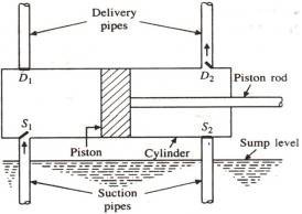
For Double Acting pump it has 2 Delivery pipes so the liquid provided per second flow rate is
Q =2LAN/60
Force on piston on Forward Stroke, F g Hs A g H A
Force on Backward Stroke, F g Hs (A) g A Hd
Total force, F g HsHd A


Q19) Write a note on Indicator diagram of reciprocating pump
A19)
Ideal indicator diagram of reciprocating pump is basically a graph between the absolute pressure head in the cylinder and the distance travelled by the piston from inner dead center for one complete revolution of the crank. As the maximum distance travelled by the piston will be equal to the stroke length and hence, we can also say that ideal indicator diagram of reciprocating pump will be basically a graph between the absolute pressure head in the cylinder and stroke length of the piston for one complete revolution.
As we know that volume of water delivered in one revolution will be the product of area of cross section of the piston or cylinder and length of stroke i.e. V = A x L
Where, cross sectional area of the piston or cylinder will be constant and therefore volume of water delivered in one revolution will be directionally proportional to the length of stroke V α L.
Therefore, ideal indicator diagram of reciprocating pump could also be considered as graph between the absolute pressure head and volume for one complete revolution of the crank.
Following figure, shown here, indicates the reciprocating pump.
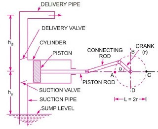
Where,
Hatm = Atmospheric pressure head
L = Length of stroke
hs = Suction head or vertical height of the cylinder axis from the water surface in the sump
hd= Delivery head or vertical height of delivery point from the cylinder axis
The graph between the absolute pressure head in the cylinder and stroke length of the piston for one complete revolution will be the ideal indicator diagram of reciprocating pump. Therefore, absolute pressure head will be taken as ordinate and stroke length will be taken as abscissa as displayed here in following figure.
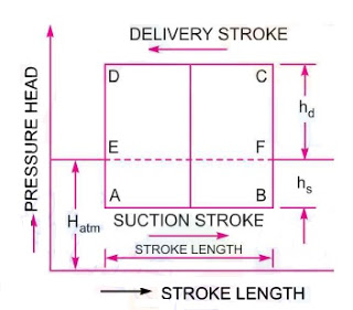
In ideal case, if we neglect the velocity and acceleration of fluid in cylinder piston and suction pipe, the suction pressure should be sufficient enough to lift the liquid i.e. water by a vertical height hs.
Therefore, suction pressure head will be equal to the vertical depth hs. In ideal case, the pressure head inside the cylinder will be constant throughout the process of suction stroke where piston moves towards outer dead center.
Therefore, AB line will indicate here the suction stroke and it will be below than the atmospheric pressure head EF as displayed in above figure.
At the end of suction stroke, piston will push the liquid i.e. water. If we assume the liquid as fully incompressible, there will be instant increase in pressure of liquid as soon as piston will push the liquid.
Because, if we recall the property of a fully incompressible liquid, liquid will be pressurized instantly without change in volume. BC line shows the instant pressure rise of liquid up to delivery pressure head when piston will push the liquid at the end of suction stroke.
CD shows the delivery stroke in above figure. During delivery stroke, the pressure head in the cylinder will be constant and will be equal to the delivery head hd and it will be above the atmospheric pressure head by a height of hd as displayed in above figure.
Total static lift of the pump will be hs + hd.
Similarly, at the end of delivery stroke when piston will come to inner dead center, there will be instant pressure drop when piston start to move towards outer dead center. This instant pressure drop, when piston start to move towards outer dead center, is shown by DA in above diagram of reciprocating pump.
Therefore, for one complete revolution of the crank, pressure head in the cylinder will be indicated by the diagram A-B-C-D-A. This diagram is known as ideal indicator diagram of reciprocating pump.
Work done by the reciprocating pump per second will be given by following equation as mentioned below.
Work done by the reciprocating pump = ρ g A L N x (hs + hd) / 60
Work done by the reciprocating pump = K x L x (hs + hd)
Since, ρ g A N / 60 = Constant = K
Therefore, we can say that
Work done by the reciprocating pump = K x AB x BC
Q20) Define air vessels.
A20)
An air vessel is a closed cast iron chamber with a bottom hole that connects to a suction or delivery pipe. Compressed air is contained in the vessel's upper part.
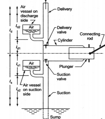
A reciprocating pump's air vessel functions similarly to an I.C. Engine's fly wheel. The compressed air at the top of the vessel can contract and expand to absorb the majority of the pressure variations. When the pressure rises, water over the mean discharge is driven into the air vessel, compressing the air inside. When the water pressure in the pipe drops, the compressed air ejects the excess water out, implying that the air vessel works as an intermediary reservoir on the suction side, accumulating water first before being delivered to the pump's cylinder. Water is sent to the air vessel first, then to the delivery pipe. The water in the pipe is constantly flowing.
Work Done by Air Vessel
In single Acting Cylinder mean Discharge from pump

Instantaneous Flow rate

Net discharge

If the equation is positive, liquid is flowing into the air vessel; if the equation is negative, liquid is flowing out of the air vessel; and if there is no liquid flowing into or out of the air vessel, the equation equals zero. The relation is parabolic


This results in two valves of ϴ =18 degrees or 161 degrees
The discharge is equivalent to mean discharge for these crank angle positions.
In double acting Pump instantaneous Discharge

Mean Discharge from pump

Net Discharge


The oscillations in the velocity of flow in suction and delivery pipes are reduced by using air vessels, which reduces head frictional losses in the pipes and saves a certain amount of energy. It is expected that the air vessel is installed relatively close to the pump cylinder, and that head loss due to friction in the tiny pipe between the pump and the air vessel is minimal. Because the flow velocity in the pipe beyond the air vessel is uniform and equal to the mean velocity, the power lost in friction per second is equal to

Power lost in friction per stroke when there is no air vessel

Power saved by fitting air vessel

The percentage of the power saved by air vessel installation

For a double-acting pump, the discharge is 2 times and lost in power per stroke is

The percentage of the power saved by air vessel installation

