Unit - 1
Control System controls
Q1) Differentiate between AC and DC Tachometer?
A1)
| D.C. Tachometer | A.C. Tachometer |
1. | They convert rotational speed into a proportional dc voltage. | They convert the rotational speed into a proportional ac voltage. |
2. | It uses a permanent magnet for producing magnetic field. It contains iron core rotor. | It works on principle of induction generator. |
3. | The permanent magnet controls the magnetic field therefore the induce voltage at terminal of armature is proportional to shaft speed. | The reference winding is supplied by reference voltage and the output voltage is induced across the output winding. |
4. | The polarity depends on direction of rotation. | The amplitude and phase depends on the direction of rotation. |
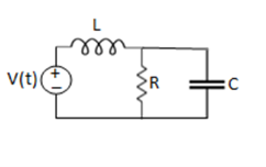
Q2) For the circuits given below write the voltage equations:
A2)
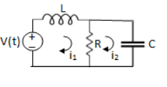
Let current i1be in loop 1 current and i2 for loop 2


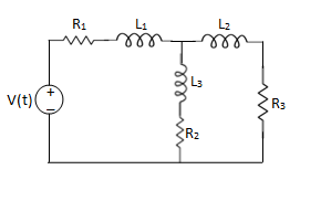
Q3) Write the loop equations for the given circuit below?
A3)
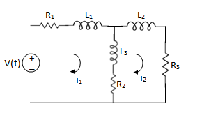
For loop 1

For loop 2

Q4) Write the integro-differential equation for the loop currents shown below.
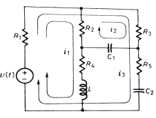
A4)
Equation for loop 1 with current i1
v(t)=(R1+R2+R4)i1 +L -R2 i2+ R5i3
Equation for loop 2 with current i2
-R2i1+(R2+R3) i2 + +R3i3 = 0
Equation for loop 3 with current i3
V(t) = R1i3+R3i3+(R1+R3+R5) i3+
Q5) For the given network write the integro differential equation?
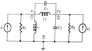
A5)
Let V1 and V2 be the node voltages.
Equation for node v1 will be
 +
+ +
+ +C1
+C1 = i1
= i1
 + C2
+ C2 + C1
+ C1 +
+ = i2
= i2
Q6) Draw the free body diagram and write the differential equation for system below.
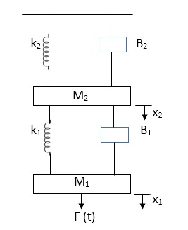
A6)
The free body diagram for M1 will be
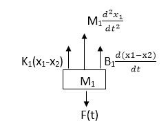
Fig. FBD for Mechanical System
F(t) = M1 d2/dt2x1+ B1 d/dt (x1-x2)+ k1(x1-x2)
Similarly for M2we have
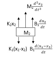
Fig. FBD for Mechanical System
K1(x1-x2) + B1d/dt(x1-x2) = k2x2+M2d2/dt2+B2dx2/dt
Q7) For the given mechanical system below draw the analogous system (force. Voltage) & find V0(s)/V1(s)
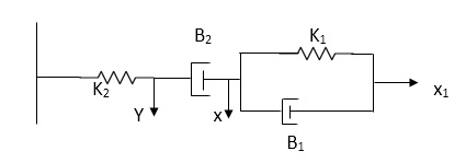
A7)
Form the table above we can find the analogus values of system components.
(1) Consider two displacement as two nodes.
(2) If masses are present connect them to reference lines
(3) Connect other elements of system to the nodes
(4) Applying modal analysis to find the system equation.
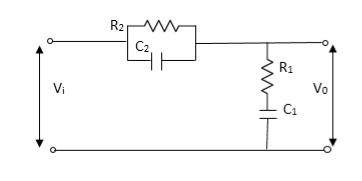
Let Z1 = R2 11 1/c2
=R2*1/c2s/R2+1/c2s
Z1= R2/1+R2c2s
Let Z2 = R1+1/c1s
Z2= 1+R1c1s/c1s
V0(s)/vi(s) = z2/z1+z2
= 1+R1c1s/c1s/R2/1+R2c2s+1+R1c1s/c1s
V0(s)/v0(s) =(c1+R1c1s) (1+R2c2s)/R2c1s+1+sR1c1s2R1R2c1c2
Q8) What are magnetic amplifiers, explain its working and types?
A8)
They are basically electromagnetic device used for amplification of electrical signals. The basic working of this amplifier depends on the saturation of core principle. It consists of two cores connected in opposite phases, with control and AC winding. By applying small amount of DC currents on control winding large amount of current on AC winding can be controlled. They are of two types
- Half wave magnetic amplifier: When DC supply is given to the control winding the magnetic flux is generated in the iron core. As flux increases the output impedance decreases and the current through AC winding in output increases. Here only half cycle of AC is utilised.

If the current through the control winding is zero, then the impedance of the output winding will be very high making no current to flow through the load or output winding. A diode is connected to the output winding which acts as a rectifier, used for reversing the polarity of the AC supply constantly from cancelling out control winding flux.
- Full wave magnetic amplifier: It utilizes both the half cycles of the AC supply. Due to wound of the two halves of the output winding the direction of magnetic flux created by these two halves in centre leg is same as direction of control winding flux
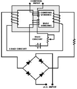
No control voltage is supplied there will be some flux present in magnetic core, hence impedance of the output winding will never attain its maximum value and current through load never attain its minimum value. The operation of the amplifier can be controlled by using the bias winding.
Q9) Explain servomechanism and ac servomotor with torque speed characteristics?
A9)
Servomechanism is also called servo which is a device usually error sensing device connected as a feedback element to correct the action of a mechanism. Here instead of controlling a device by variable input signal, the device is controlled by feedback signal.
The input signal applied to such systems generate the required output which is compared again to the input signal. If the device achieves its desired output, there will be no longer the logical difference between the two signals. Hence, the primary task of servomechanism is to maintain the output of a system at the desired value in the presence of disturbances.
A.C. Servomotors:
A.C servomotor is a two-phase ac induction motor. There are two windings in this motor, one is fixed or reference winding is supplied with a fixed voltage and frequency from a constant voltage source. Second winding is control winding with variable supply voltage of same frequency as reference winding but having a phase displacement of 900 electrical. A flux is induced due to the phase change which cuts the conducting bars of rotor and causes a time varying current, this current produces a time varying flux and reacts with the stator flux causing the rotor to rotate.
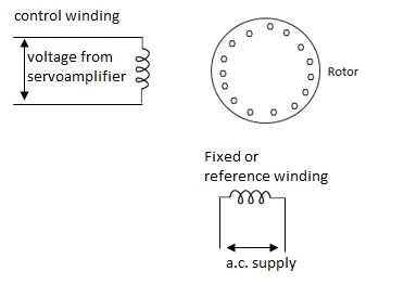
The rotor of A.C. Servomotos are of two types,
(a). Squirrel Cage Rotor
(b). Drag cup type rotor
(a). Squirrel cage rotor: They have high resistance as the rotor is having large length and small diameter. The air gap here is kept small.

(b). Drag cup type motor: For the drag cup rotor there are two air gaps. For the rotor a cup of non-magnetic conducting material is used. A stationary iron core is placed between the conducting cup to complete the magnetic circuit. The resistance of drag cup type is high and therefore, has high starting torque. Generally aluminium is used for cup.
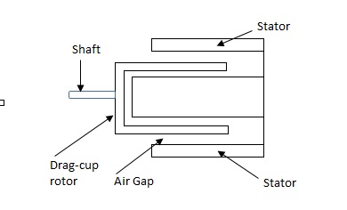
Torque-speed characteristic:
The torque speed characteristics of the two phase servomotor depends on ratio of reactance to resistance(X/R).
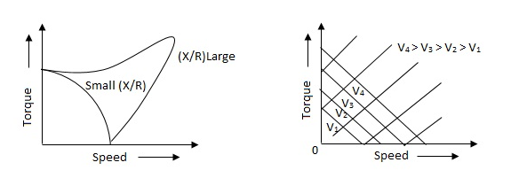
(i). For high ‘R’ and low X, the characteristic is linear and
(ii). For high X and low R, it becomes non-linear.
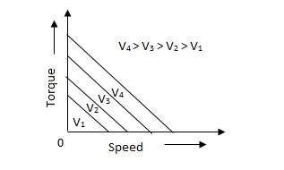
The torque-speed characteristic for various voltage is almost linear.
Q10) What are tachometers and list the difference between its types?
A10) These are electromechanical devices which convert mechanical input at their shaft to corresponding electrical output. It is basically used to measure speed of motor. It has negative feedback. These devices are most commonly used to find speed of any rotating machine.
| D.C. Tachometer | A.C. Tachometer |
1. | They convert rotational speed into a proportional dc voltage. | They convert the rotational speed into a proportional ac voltage. |
2. | It uses a permanent magnet for producing magnetic field. It contains iron core rotor. | It works on principle of induction generator. |
3. | The permanent magnet controls the magnetic field therefore the induce voltage at terminal of armature is proportional to shaft speed. | The reference winding is supplied by reference voltage and the output voltage is induced across the output winding. |
4. | The polarity depends on direction of rotation. | The amplitude and phase depends on the direction of rotation. |
Q11) Explain synchros transformer?
A11) Its basic working principle is similar to the synchro transformer. Here the rotor is cylindrical type. It is an electromechanical device. The combination of synchro transmitter and synchro transformer is used as an error detector.
The basic diagram is shown below,
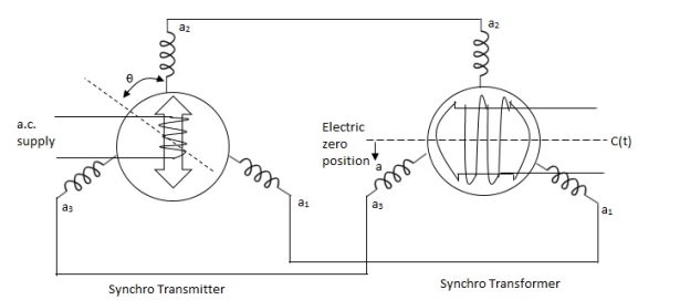
Fig. Synchros Transformers
Let transmitter rotate at an angle ϴ and control transformer rotor rotate in same direction through α. Then,
φ = ( 90 - ϴ + α )
Voltage across rotor terminal is given as,
e(t) = K1Vrcos ϴSinwot
e(t) = K1VrSin(ϴ - α) Sin wot
From above equation we can conclude that when two rotor shafts are not aligned, the rotor voltage of transformer is a sine function of difference between two angles.
For small angular displacement between two rotor position
e(t) = K1Vr(ϴ - α)Sinwot
Q12) For circuit shown above find value of current I?
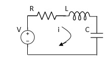
Fig. RLC Circuit
A12)
Applying Kirchoff’s voltage Law
V= Ri +Ldi/dt +1/c
V= Rdq/dt + L d2q/dt2+q/c
Now By kirchoff’s current low
I= V/R+ 1/L  + cdv/dt
But V= dø/dt
I= 1/R dø/dt + 1/L ø+cd2ø/dt2
But v= dø/dt
I= 1/R dø/dt+ 1/L. ø+c d2ø/dt2
Q13) For the given mechanical system below draw the analogus system (force. Voltage) & find V0(s)/V1(s)
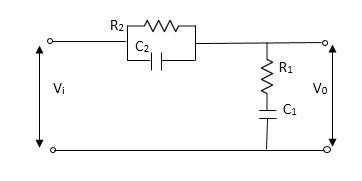
A13)
Let Z1 = R2 11 1/c2
=R2*1/c2s/R2+1/c2s
Z1= R2/1+R2c2s
Let Z2 = R1+1/c1s
Z2= 1+R1c1s/c1s
V0(s)/vi(s) = z2/z1+z2
= 1+R1c1s/c1s/R2/1+R2c2s+1+R1c1s/c1s
V0(s)/v0(s) =(c1+R1c1s) (1+R2c2s)/R2c1s+1+sR1c1s2R1R2c1c2
Q14) What is a transfer function of control system? Explain the concept of poles and zeros?
A14)
It is the ratio of Laplace transform of the output to Laplace transform of input with all initial conditions zero.

Fig. System with Transfer Function G(s)
Poles and zero of a Transfer Function:
The transfer function can be represented by the ratio of two polynomials
G (S) = a0sn+a1 sn-1-------+an/b0sm+b1sm-1+-----+bn
a0—an ---- constants
G(S) = K(s+z1) (s+z2) (as2+bs+c)/(S+A) (s+p2) (As2+Bs +c)
K= a0/b0 ( Gain of system)
For poles –They are the values of s for which
G(S)
(S+p1)(S+p2)(AS2 + BS + C) = 0
S= p1, -p2 , -B±B2-4Ac/2A
For ZEROS – They are the values of s for which
G(S)0
S=-z1, -z2 , -b±b2-4ac/2a
- Location of poles and zeros in s place determines the reliability of the system
- There can be multiple poles and zeros
- The numerator of transfer function when equalized to zero gives zero of system
- The denominator of transfer function which equalized to zero gives poles of system.
Q15) Explain the properties of Laplace Transform?
A15)
It is a technique for solving differential equations. The time domain differential equations are transformed into algebraic equation of frequency domain. After solving the algebraic equation in frequency domain, the result then is finally transformed to time domain form to achieve the ultimate solution of the differential equation.
The Laplace Transform is given as
F(s)= dt
dt
The advantages of Laplace Transform are:
1) It is systematic.
2) It gives total solution (transient and sustained solution) in one operation.
3) The initial conditions are automatically specified in the transformed equations.
There are many functions which do not have Laplace Transforms. These functions are not generally used in analysis of linear systems. But some conditions can be defined to get Laplace transformation of such functions. The Dirichlet condition defines the necessary condition for transformation of some functions such as:
a) The function should be continuous. The function should be single-valued.
b) The function must be of exponential order.
Properties of Laplace Transform:
1) Linearity Property:
If f1(t) and f2(t) are two functions of time. Then, in domain of convergence
L[a f1(t)+b f2(t)]=a + b
+ b
=aF1(s)+bF2(s)
2) Differentiation Property:
If x(t) is function of time then Laplace transform of nth derivative is given as


3) Integration Property:
The Laplace of nth order integral is given as
L[ ]=
]= +
+
L[f-n(t)]= +
+ +
+ +……….
+……….
As 
 ……..=0. Hence
L[f-n(t)]=
Q16) Derive expression of Laplace Transform of basic R, L and C components?
A16)
LAPALACE TRANSFORM:
If LT[f(t)]= F(s)
Where F(s)= dt
dt
f(t) F(s)
F(s)

 sF(s)-f(0-)
 f(t)
f(t) S2F(s)-sf(0-)-f’(0-)
Now, we find Laplace for 
 =
= +
+
Now if f(t)=ic(t) [current through capacitor]
 =
= +
+
 =
= +
+
=[q(0)-q( )]+
)]+
=[q(0)-0]+
Multiplying both sides by 1/C
 =
= +
+
Vc(t)= +
+
Vc(t)=Vc(0)+
By Laplace Transform
Vc(s)= +
+
Vc(s)= +
+

Fig. Laplace transformed circuit for C
Now by source conversion
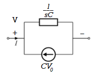
Fig. Source transformed circuit for C
 =
= +
+
Now if f(t)=VL(t) [voltage across inductor]
 =
= +
+
 =
= +
+
= -
- ]+
]+
= -0]+
-0]+
Multiplying both sides by 1/L

 =
= +
+
iL(t)=iL(0)+
By Laplace Transform
IL(s)= +
+
IL(s)= +
+
NOTE: Voltage------->Series circuit
Current------->Parallel circuit
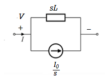
Fig. Laplace transformed circuit for L
By source transformation

Fig. Source transformed circuit for L
Current through capacitor
iC(t)=
IC(s)=C[sVc(s)-Vc(0)]
Vc(s)= +
+
Voltage about inductor,
VL(t)=
VL(s)=L[sIL(s)-iL(0)]
IL(s)= +
+
Q17) Compare open loop and closed loop systems?
A17)
Open Loop System | Closed Loop system |
1.It does Not have any feedback. | 1. This system comprise of feedback |
2.As no feedback so easier to build. | 2.As it has feedback so difficult to build |
3.Theaccuracy of this system depends on the calibration of input. | 3.They are accuracy because of the feedback. |
4.Open Loop system are more stable. | 4.In closed Loop system stability depends on system components. |
5.optimization is not possible | 5. Optimization is possible |
6.These systems are not reliable. | They are more reliable |
Q18) What are prime movers?
A18)
The actual meaning of prime mover is a primary source of power. It means all the machinery that provide power for performing different mechanical work. Technically, it is a group of machines that transform energy from thermal, electrical or pressure into mechanical form for use in different sources for some mechanical work. Engines and turbines are examples.
The prime movers are listed based on the sources of energy utilized by them.
A. Thermal prime movers These are the prime movers which use the thermal energy of source to produce power. Different thermal prime movers are given below: -
Fuels (Heat engines): - These prime movers use several fuels like petrol, diesel, oil, gas to produce mechanical power. Heat engines are two types: -
1. External combustion engines: -Reciprocating steam engines Steam turbine Closed cycle gas turbine
2. Internal combustion engines: -Reciprocating I.C. Engines Open cycle gas turbine
- Nuclear (Nuclear power plant): - This prime mover utilises the heat energy of atoms by fission or fusion method to develop the mechanical power. It is chiefly used in nuclear power plants. Different radioactive components like uranium, thorium is used for these fission or fusion process in a nuclear reactor.
- Geothermal: - In this kind of prime mover the heat energy is recovered from a certain depth or the hot part of the earth beneath earth surface then it is transformed into mechanical by the proper engine.
- Biogas: - Biogas is principally produced from garbage or any other waste which is used to generate power by the prime mover in a biogas plant.
- Solar energy: - The solar energy spread to the earth in the form of radiation or electromagnetic waves. This energy trapped in with the help of solar panel made up of semiconductor element. This heat energy is then turned into power.
B. Non-thermal prime movers: - These kinds of prime movers do not use the heat energy to transform it into mechanical power. The following are the non-thermal prime movers:
- Hydraulic turbines: - This kind of prime mover uses the stored potential energy of water to generate power.
- Wind power: - With the help of the wind turbine, wind energy is transformed into power.
- Tidal power: - The energy of tides from the ocean is transformed into power by the use of the turbine which is known as tidal power.
Q19) Write short notes on automobile steering control?
A19)
- Collection of components which allows to follow the desired course.
- In a car: ensure that wheels are pointing in the desired direction of motion.
- Convert rotary motion of the steering to the angular turn of the wheel.
- Mechanical advantage is used in this case.
- The joints and the links should be adjusted with precision.
- Smallest error can be dangerous
- Mechanism should not transfer the shocks in the road to the driver's hands.
- It should minimize the wear on the tyres.
RACK AND PINION STEERING SYSTEM
- The pinion moves the rack converting circular motion into linear motion along a different axis
- Rack and pinion give good feedback there by imparts a feel to the driving
- Most commonly used system in automobiles now.
- Disadvantage of developing wear and there by backlash.
RECIRCULATING BALL
- Used in Older automobiles
- The steering wheel rotates the shaft which turns the worm gear.
- Worm gear is fixed to the block and this moves the wheels.
- More mechanical advantage.
- More strength and durable
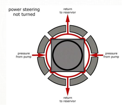
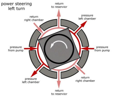
POWER STEERING
- Too much physical exertion was needed for vehicles
- External power is only used to assist the steering effort.
- Power steering gives feedback of forces acting on the front wheel to give a sense of how wheels are interacting with the road.
- Hydraulic and electric systems were developed.
- Also, hybrid hydraulic-electric systems were developed.
- Even if the power fails, driver can steer only it becomes heavier.
ELECTRIC POWER STEERING
- Uses an electric motor to assist the driving
- Sensors detect the position of the steering column.
- An electronic module controls the effort to be applied depending on the conditions.
- The module can be customised to apply varying amounts of assistance depending on driving conditions.
- The assistance can also be tuned depending on vehicle type, driver preferences
Q20) Write short notes on liquid level control?
A20)
Consider the flow through a short pipe connecting two tanks. The Resistance, R for liquid flow in such a pipe or restriction, is defined as the change in the level difference, necessary to cause a unit change in the flow rate.
R = Change in level difference/Change in flow rate
The Capacitance, C of a tank is defined to the change in quantity of stored liquid necessary to cause in the potential (head).
C = Change in liquid stored/Change in head
A simple liquid level system is shown in the below figure with steady flow rate, Q and steady state head, H.
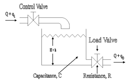
Fig. Liquid Level System
Let Q = Steady state flow rate(before any change has occured)
Qi = Small deviation of inflow rate from its steady-state value
Qo = Small deviation of outflow rate from its steady-state value
H = Steady state head (before any change has occurred)
h = Small deviation of head from its steady state value
Let the system be considered linear. The differential equation governing the system is obtained by equating the change in flow rate to the amount stored in the tank. In a small time interval dt, let the change in flow rate be (qi - qo) and the change in height be dh.
Now, Change In storage = Change in flow rate
C dh = (qi - qo) dh

Qo = h/R
On substituting for qo, we get,
 RC dh/dt + h = qi R
The above equation is the differential equation governing the system. The term RC is the time constant of the system .On the Laplace's transform of above equation we get,


The above equation is the required transfer function of the Hydraulic system.