Unit - 2
Transfer Function system Representation through Block Diagram and Signal Flow Graph
Q1) Find SFG for the block diagram below?
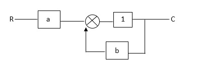
A1)
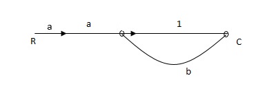
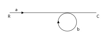
Ra+cb =c
c/R= a/1-b
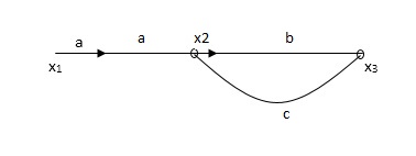
Q2) The SFG shown has forward path and singles isolated loop determine overall transmittance relating X3 and X1?
A2)
X1- I/p node
X2-Intenmediale node
X3- o/p node
Ab- forward path (p)
Bc- 1 loop (L)
At node XQ:
X2 = x1a + x3c [Add i/p signals at node]
At node x3:
x2b =x3
(x1a+x3c) b = x3
X1ab = x3 (1-bc)
X1 = x3 (1-bc)/ab
Ab/(1-bc) = x3/x1
T= p/1-L

X1:- I/p node x2, x3,x4,x5,Qnlexmedili node
X0:- o/p node abdeg:- forward path
Bc, ef :- Loop [isolated]
x2 = ax1+c x3
x3= bx2
x4 = d x3+f x5
x5 = e x4
x6= g x5
x6 = g(e x4) = ge [dx3+ e f x5]
xb = ge [d (bx2) + f (e x4)]
xb = ge [ db (ax1+cx3) + fe (dx3+ fx5)]
xb = ge [db (ax1+cb (ax1+x3) +fe[cdbx2]+
f( e [db (ax1+ cx3)
x2 = ax1 + cb (x2) x4 = d bx2 + f exq
x2 = ax1 + cbx2 = db (d4) + fe/1-cb
x2 = ax1/(1-cb) xy = db x2 + f x6/g
xy = db [ax1]/1-cb + f xb/g
x5 = c db ( ax1)/1-cb + efxb/g
xb = gx5
= gedb (ax1)/1-cb + g efxb/g
Xb = gx5
Gedb (ax1)/1-cb + g efxb/g
(1-gef/g) xb = gedb ax1/1-ab
Xb/x1 = gedb a/ (1- ef – bc + beef
Xb/x1 = p/ 1- (L1+L2) + L1 L2for isolated loops
Q3) Reduce given B.D to canonical (simple form) and hence obtain the equivalent Tf = c(s)/ R(S)?
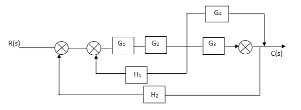
A3)
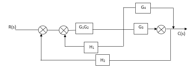


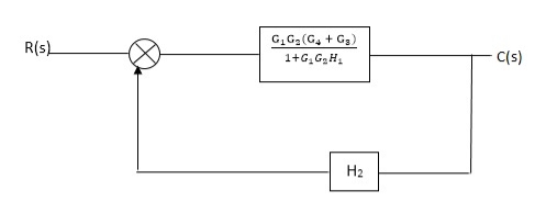
Fig. Final reduced block diagram
C(S)/R(S) = (G1G2) (G3+G4)/1+G1G2H1)/1-G1,G2(G3+G4) H2/1+G1G2H1
= G1G2(G3+G4)/1+G1G2H1-G1G2H2(G3+G4)
=G1G2(G3+G4)/1+(H1-H2)(G1G2) (G3+G4)
C(s)/R(S) = G1G2(G3+G4)/1+(H1-H2(G3+G4)) G1 G2
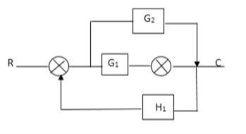
Q4) Reduce using Masons gain formula
A4)
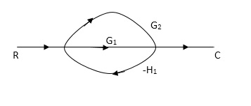
P1= G1 p2 =G2 Delta1 =1
L1= -G1 H1
 = 1-(-G1H1)
= 1+G1H1
T= G1+G2/1+G1H1
Q5) Determine overall gain reliably x5 and x1 Draw SFG
X2 = ax1+ f x2
X3= bx2 +exy
X4 = cx3+hx5
X5 =dx4 + gx2
A5)
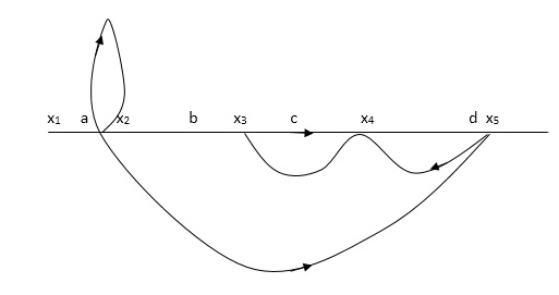
P1 = abcd p2 = ag
L1 = f L2 = ce, L3= dh
 1 = 1
1 = 1
 2= 1-ce
 = 1-[L2+L2+L3] + [L1 L2 +L1 L3]
= 1-[f+ le = dh] + [fce +fdh]
T= abcd+ ag (1-ce)/1-[ftce + dh ] + (fce + fdh)
Q6)Write short note on hydraulic system and also mention its types?
A11) The Hydraulic system of interest to control engineers may be classified into,
1.Liquid Level system
2.Hydraulic devices
The liquid level system consists of storage tanks and connecting pipes. The variables to be controlled are liquid height in tanks and flow rate in pipes. The driving force is the relative difference of the liquid heights in the tanks. The Hydraulic devices are devices using incompressible oil as their working medium. In this we will be learning transfer function of hydraulic system.
These devices are used for controlling the forces and motions. The driving force is the high-pressure oil supplied by the Hydraulic pumps. Liquids are slightly compressible at high pressures.
In hydraulic system, the compressibility effects may be neglected and conservation of volume is used as the basic physical law. The variables of hydraulic system are volumetric flow rate, q and pressure, R The volumetric flow rate, q is through variable and it is analogous to current. The pressure, P is across variable and it is analogous to voltage.
Three basic elements of hydraulic systems are the Resistance, Capacitance and lnertance. The liquid flowing out of a tank can meet the resistance in several ways. Liquid while flowing through a pipe meet with resistance due to the friction between pipe walls and liquid. Presence of valves, bends, coupling of pipes of different diameter also offer resistance to liquid flow.
The capacitance is an energy storage element and it represents storage in gravity field. The inertance represents fluid inertia and is derived from the inertia forces required to accelerate the fluid in a pipe. It is also an energy storage element. But the energy storage due to inertance element is negligible compared to that of capacitance element.
Consider the flow through a short pipe connecting two tanks. The Resistance, R for liquid flow in such a pipe or restriction, is defined as the change in the level difference, necessary to cause a unit change in the flow rate.
R = Change in level difference/Change in flow rate
The Capacitance, C of a tank is defined to the change in quantity of stored liquid necessary to cause in the potential (head).
C = Change in liquid stored/Change in head
A simple liquid level system is shown in the below figure with steady flow rate, Q and steady state head, H.
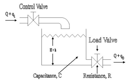
Fig. Liquid Level System
Let Q = Steady state flow rate(before any change has occured)
Qi = Small deviation of inflow rate from its steady-state value
Qo = Small deviation of outflow rate from its steady-state value
H = Steady state head (before any change has occurred)
h = Small deviation of head from its steady state value
Let the system be considered linear. The differential equation governing the system is obtained by equating the change in flow rate to the amount stored in the tank. In a small time interval dt, let the change in flow rate be (qi - qo) and the change in height be dh.
Now, Change In storage = Change in flow rate
C dh = (qi - qo) dh

Qo = h/R
On substituting for qo, we get,
 RC dh/dt + h = qi R
The above equation is the differential equation governing the system. The term RC is the time constant of the system .On the Laplace's transform of above equation we get,


The above equation is the required transfer function of the Hydraulic system.
Q7) List advantages and disadvantages of block diagram reduction?
A7)
Advantages of Block diagram reduction technique:
- Very simple to Construct the Block diagram of complicated electrical & mechanical systems.
- The function of individual element can be visualized form block diagram
- Individual as well as overall performance of the system can be studied by the figure shown in Block diag.
- Overall CLTF can be easily calculated by Block diagram reduction rules.
Disadvantages of Block diagram reduction technique:
It does not include any information above physical construct of system (completely mathematical approach). Source of energy is generally not shown in the block diagram so diff. Block diagram can be drawn for the same function.
CLTf: -ve feedback
C(s)/R(s)= G(s)/1+G(s)H(s)
CLTF:-+ve feedback
C(S)/R(S) = G(S)/1-G(s)H(S)
Q8) Taking examples list the rules of block diagram reduction?
A8)
Rules of Block diagram Algebra:
Block in cascade


Moving summing point after a block

Moving summing point ahead of block

Moving take off point after a block

Moving take off point ahead a block

Eliminating a feedback Loop

Fig. Block Diagram Reduction Techniques
Q9) Find the observable canonical realization of the system H(s)=
A9)
The above transfer function can be also written as
H(s)=
Comparing above equation with standard equation we conclude that
The gains of forward paths are 
The feedback loop gains are 
The SFG satisfying above conditions will be
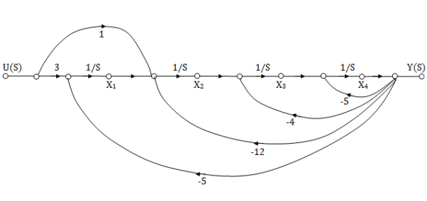
The observable canonical form can be obtained by converting the above SFG to block diagram
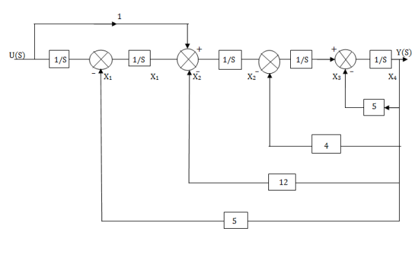
Fig. Observable canonical form can be obtained by converting the above SFG to block diagram
Q10) Reduce the give block diagram to find the transfer function?

A10)
The above block diagram can be reduced as shown below

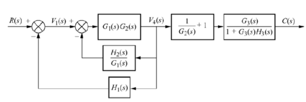


From above reduced figure the transfer function is very clear.
Q11) Reduce the given figure using block diagram reduction to find its transfer function?
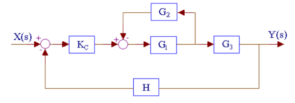
A11)
The above system can be reduced as

Kc, (G1/1+G1G2) and G3 are in series. H is in feedback with them.

Q12) Reduce the given system using block diagram reduction technique?
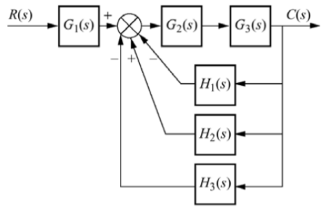
A12)
The figure can be reduced as
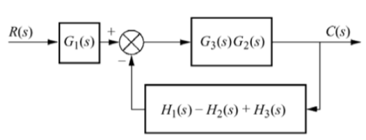
G1 and G2 are in series and H1, H2 and H3 are in parallel.

G1 is in series with feedback configuration. The transfer function becomes
C(s)/R(s) =

Q13) Compute the transfer function of the given figure?
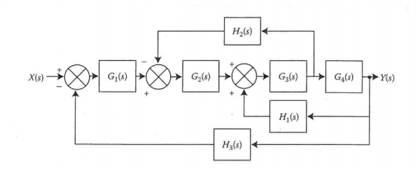
A13)
The branch point at the left of the block with transfer function G4(s) is moved at the right of G4(s). The equivalent block diagram is
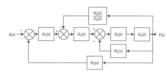
The transformation is applied to blocks with transfer function G3(s), G4(s) and H1(s).
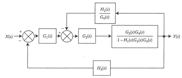
We apply transformation to the loop with TF H2(s)/G4(s) we get

Again, applying same transformation to above figure we get the final reduced structure

Q14) Derive the transfer function of thermal system?
A14)
Thermal systems are those that involve the transfer of heat from one substance to another. The model of thermal systems is obtained by using thermal resistance and capacitance which are the basic elements of the thermal system. The thermal resistance and capacitance are distributed in nature. But for simplicity in analysis lumped parameter models are used.
Consider a simple thermal system shown in the below figure. Let us assume that the tank is insulated to eliminate heat loss to the surrounding air, there is no heat storage in the insulation and liquid in the tank is kept at uniform temperature by perfect mixing with the help of a stirrer. Thus, a single temperature is used to describe the temperature of the liquid in the tank and of the out flowing liquid. The transfer function of thermal system can be derived as shown below.
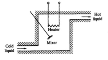
Fig. Thermal System
Let θ1 = Steady state temperature of inflowing liquid, °C
θ0 = Sandy state temperature of outflowing liquid, °C
G = Steady state liquid flow rate, Kg/sec
M = Mass of liquid in tank, Kg
c = Specific heat of liquid, Kcal/Kg °C
R = Thermal resistance, °C - sec/Kcal
C = Thermal capacitance, Kcal/°C
Q = Steady state heat input rate, Kcal/Sec
Let us assume that the temperature of inflowing liquid is kept constant. Let the heat input rate to the thermal system supplied by the heater is suddenly changed from Q to Q + q1. Due to this, the heat output flow rate will gradually change from Q to Q + q0. The temperature of the outflowing liquid will also be changed from θ0 to θ0 + θ.
For this system the equation for q0, C and R is obtained as follows,

Thermal capacitance, C = Mass, M x Specific heat of liquid, c = Mc

On substituting for qo from equation (1) in equation (3) we get,

In this thermal system, rate of change of temperature is directly proportional to change in heat input rate.


The constant of proportionality is capacitance C of the system.
Equation (5) is the differential equation governing system. Since, equation (5) is of first order equation, the system is first order system.
From equation (3), R = θ/q0
q0 = θ/R
On substituting for q0 from equation (6) in equation (5) we get,


Let, L {θ} = θ(s); L{dθ/dt} = sθ(s) ; L{q1} = Q1(s)
On taking Laplace transform of equation (7)
RC s θ(s) + θ(s) = R Q1(s)
θ(s) [sRC + 1] = R Q1(s)
θ(s)/Q1(s) is the required transfer function of thermal system.

Q15) Find the controllable canonical realization of the following systems H(s)=
A15)
H(s)=
Let H(s)=
 =
=
H1(s)= 1/s+6
1/s+6
X(s)=sX1(s)+6X1(s)
SX1(s)= X(s) +6X1(s)
We can get X1(s) by passing sX1(s) through integrator. The above equation can be realised as
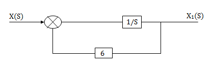
Fig. H1(s)= 1/s+6
1/s+6
H2(s)= s+2
s+2
Similarly, Y(s)= sX1(s)+2X1(s)
H2(s)= s+2
s+2

Fig. H2(s)= s+2
s+2
The complete realization of transfer function can be obtained by combining the above two realizations. The complete realization will be
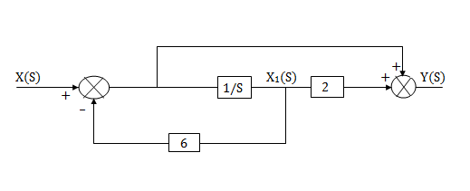
Fig. Complete realization of H(s)=
Q16) Find the controllable canonical realization of the following systems
H(s)=
A16)
Let H(s)= =
= 
 =s+3
=s+3
Y(s)=sX1(s)+3X1(s)
The above transfer function can be realised as

Fig.  =s+3
=s+3
Now,  =
=
s2X1(s)=X(s)-2sX1(s)-5X1(s)
Assuming s2X1(s) is available the above transfer function can be realised as
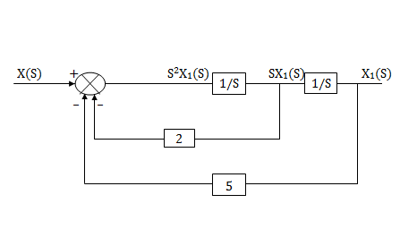
Fig.  =
=
The complete realization of transfer function can be obtained by combining the above two realizations. The complete realization will be
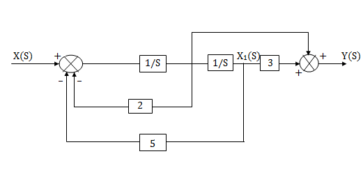
Fig. H(s)=