Unit - 4
Turning moment Vs crank angle diagram for single- cylinder and multiple-cylinder engines
Q1) Define Turning Moment Diagram
A1)
Turning Moment Diagram -Definition
Turning second diagram is a graphical illustration of turning second or torque (alongside Y-axis) as opposed to crank perspective (X-axis) for diverse positions of a crank. It is likewise known as a Crack attempt Diagram. It is plotted on cartesian coordinates, wherein the turning second is taken because the ordinate and crank perspective as abscissa.
Q2) Give the significance of turning moment diagram.
A2)
Significance of Turning Moment Diagram:-
1. It indicates version of Turning second with admire to the crank perspective of an Engine.
2. The version of Torque suggests the dimensions of Flywheel
3. More version suggests Larger Flywheel and vice-a-versa.
4. Single curve version is a sign of unmarried-cylinder engine.
5. More than one curve suggests Multi-cylinder engine.
6. Area beneath neath and above of the suggest torque line indicated the requirement of electricity or technology of electricity all through that perspective.
The above factors may be nicely understood and defined through the Turning second diagram and we will layout the right flywheel for the engine for lowering the rate version of the crank all through every cycle.
Uses of Turning Moment Diagram
The paintings performed according to cycle while divided through the crank perspective according to cycle offers the suggest torque T m.
The suggest torque Tm extended through the angular pace of the crank offers the electricity fed on through the gadget or advanced through an engine. The place of the TMD above the suggest torque line represents the extra power that can be saved through the flywheel, which allows to layout the dimensions & mass of the flywheel.
Turning Moment Diagram
For Single cylinder double performing engine
A turning second diagram for a unmarried cylinder double performing steam engine is proven in Fig.
The vertical ordinate represents the turning second and the horizontal ordinate represents the crank perspective.
The turning second at the crankshaft,
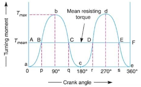
Fig. Turning moment diagram for single cylinder acting engine
Where
FP = Piston effort,
r = Radius of crank,
n = Ratio of the connecting rod length and radius of the crank, and
θ = Angle turned by the crank from the inner dead center.
From the above expression, we see that the turning second (T) is 0 whilst the crank perspective (θ) is 0.
It is most whilst the crank perspective is 90° and it's far once more 0 whilst the crank perspective is 180°.
This is proven through the curve abc in Fig and it represents the turning second diagram for outstroke.
The curve cde is the turning second diagram for in stroke and is extremely just like the curve abc.
Since the paintings carried out is the fabricated from the turning second and the perspective turned, consequently the region of the turning second diagram represents the paintings carried out in line with revolution.
In real practice, the engine is thought to paintings in opposition to the imply resisting torque, as proven through a horizontal line AF.
The peak of the ordinate aA represents the imply peak of the turning second diagram.
Since it's far assumed that the paintings carried out through the turning second in line with revolution is identical to the paintings carried out in opposition to the imply resisting torque, consequently the region of the rectangle aAFe is proportional to the paintings carried out in opposition to the imply resisting torque.
Q3) Explain Turning Moment Diagram for Single Cylinder 4 Stroke I.C. Engine
A3)
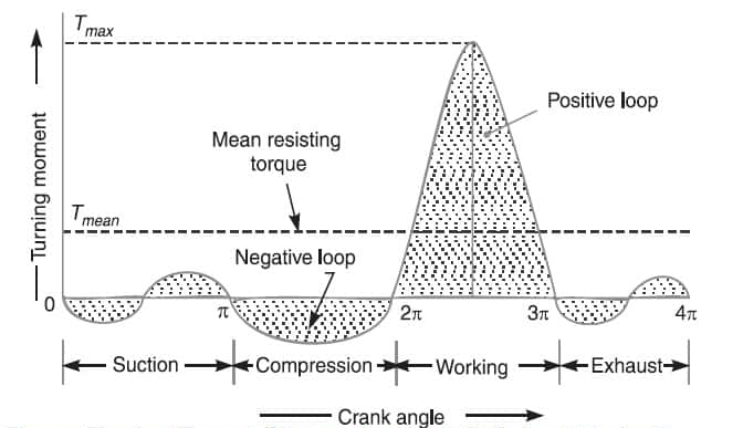
We know that in a four-stroke cycle internal combustion engine, there is one working stroke after the crank has turned through two revolutions, i.e. 720° (or 4 π radians).
The inner of an internal-combustion engine is a pretty much the maximum violent area on Earth.
For an engine to live to tell the tale all of the rocking and rolling it produces, the ones forces want to be counterbalanced with same—or as a minimum almost same—forces.
Text, Red, White, Line, Font, Colorfulness, Carmine, Orange, Parallel, Rectangle, “The forces that effect engine stability come from 3 sources,” explains Kevin Hoag, the accomplice director of the Engine Research Center on the University of Wisconsin–Madison
To counter the rotational and reciprocating forces, the cylinders in a single financial institution circulate in actual competition to the ones of the other, thereby absolutely canceling the forces created via way of means of every.
For example, a 4-cylinder would love to hearthplace at each a hundred and eighty levels of crankshaft rotation (720/4=a hundred and eighty). Having firing occasions that arise in same increments, as on this instance, is fine for stability. The flat-4 fires at a hundred and eighty-diploma intervals, and its V attitude is a hundred and eighty levels, which results in a stability of firing forces. The flat-4, in fact, balances all 3 of the exclusive forms of forces.
A cross-aircraft, ninety-diploma V-eight has balanced rotational and reciprocating forces as it is lots like 4 of the balanced ninety-diploma V-2s proven withinside the aforementioned illustration. To stability the firing pressure, a cylinder has to hearthplace each time the crankshaft rotates ninety levels. Since the financial institution attitude is ninety levels and the firing forces arise in ninety-diploma intervals, the cross-aircraft V-eight additionally manages to stability all 3 of the forces.
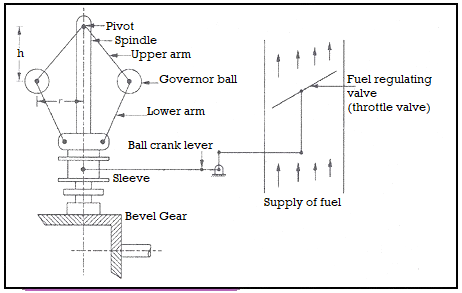
Fig. Turning moment diagram for single cylinder 4 stroke IC engine
[1] Since the pressure inside the engine cylinder is less than the atmospheric pressure during the suction stroke, therefore a negative loop is formed as shown in Fig.
[2] During the compression stroke, the work is done on the gases; therefore a higher negative loop is obtained.
[3] During the expansion or working stroke, the fuel burns and the gases expand; therefore a large positive loop is obtained. In this stroke, the work is done by the gases.
[4] During the exhaust stroke, the work is done on the gases; therefore a negative loop is formed.
Q4) Explain Cylinder and multiple-cylinder engines, punching machines etc.
A4)
Without any context, it isn't viable to mention that both one is higher than the other. For small ability engines, unmarried cylinder engines are higher, as they're less expensive to manufacture (much less cylinders, much less parts, and much less cost). Single cylinder additionally gives higher torque output and at decrease RPMs in comparison to a multi-cylinder engine.
On the contrary, a multi-cylinder engine will usually provide you with better energy output at height rpm. Single cylinder engines are theoretically constantly imbalanced absolutely balancing a unmarried cylinder engine isn't always viable. So they may constantly have greater vibrations while in comparison to multi cylinder engines. But they're greater compact in comparison to multi cylinder engines. So they are able to match into tight areas less difficult. Multiple cylinder engines may be turbocharged for higher energy and efficiency. Single cylinder engines can't be turbocharged.
It is usually less difficult to have an air cooled unmarried cylinder engine. It's hard to make a feasible air cooled multi cylinder engine. There are professionals and cons to each the designs. Which is why they're used for distinct purposes. Unless, you've got a particular application, it's far pretty not possible to mention if one is higher than the other.
Compared with multi-cylinder engines, unmarried-cylinder engines are generally less complicated and compact. Due to the extra ability for airflow round all facets of the cylinder, air cooling is frequently greater powerful for unmarried cylinder engines than multi-cylinder engines.
This reduces the load and complexity of air-cooled unmarried-cylinder engines, in comparison with liquid-cooled engines. Drawbacks of unmarried-cylinder engines encompass a greater pulsating energy shipping via every cycle and better tiers of vibration.
The choppy energy shipping method that frequently a unmarried-cylinder engine calls for a heavier flywheel than a similar multi-cylinder engine, ensuing in enormously slower modifications in engine speed. To lessen the vibration level, they frequently make extra use of stability shafts than multi-cylinder engines, in addition to greater severe techniques which include a dummy connecting rod (as an instance the Ducati Supermono).
These balancing gadgets can lessen the blessings of unmarried-cylinder engines concerning decrease weight and complexity. Most unmarried-cylinder engines utilized in motor cars are fueled with the aid of using petrol (and use a four-stroke cycle), but diesel unmarried-cylinder engines also are utilized in desk bound applications (which include the Lombardini 3LD and 15LD).
Q5) Explain flywheel selection.
A5)
Flywheels are heavy rotating disks which have a excessive mass and are linked to a rotating shaft. Because they shop angular momentum, flywheels provide a easy shipping of torque, or turning energy, from a motor or engine. The inertia of flywheels lets in them to soak up and launch strength with little alternate in speed.
Specifications Flywheels had been used for decades in all forms of equipment to make sure regular shaft rotation while a choppy torque is applied, inclusive of in a reciprocating or piston-pushed engine. Flywheels also can be used to shop up kinetic strength this is launched to offer quick periods of extra energy output in small motors.
A popular shift flywheel is established at the engine shaft and disengages in short from a stress plate established at the transmission shaft while the motive force places a foot at the seize to shift gears.
When the motive force gets rid of a foot from the seize, a friction plate is sandwiched among the flywheel and the stress plate, permitting the engine shaft to show the transmission.
Cars and vehicles with guide or popular transmissions use flywheels of various weights relying on the scale of the automobile and the engine. A truck flywheel is heavier to shop extra strength and offer extra acceleration.
Features
Aluminum flywheels are utilized in a few vehicles. An aluminum flywheel is lighter in weight than a metallic flywheel, permitting an engine to shift faster. Aluminum flywheels make bigger at two times the charge of metallic, so that they need to be tightened nicely at ambient temperatures to make sure choicest capability while the engine is running.
Aluminum flywheels are utilized in excessive overall performance engines due to the fact they're long lasting and strong, however also are light-weight and positioned much less strain at the crankshaft.
A flywheel is a mechanical tool which makes use of the conservation of angular momentum to shop rotational strength; a shape of kinetic strength proportional to the manufactured from its second of inertia and the rectangular of its rotational speed.
In particular, assuming the flywheel's second of inertia is constant (i.e., a flywheel with constant mass and 2d second of region revolving approximately a few constant axis) then the saved (rotational) strength is without delay related to the rectangular of its rotational speed.
Since a flywheel serves to shop mechanical strength for later use, it's miles herbal to don't forget it as a kinetic strength analogue of an electrical inductor.
As with different forms of accumulators, a flywheel inherently smooths small enough deviations withinside the energy output of a device, thereby correctly gambling the position of a low-by skip clear out with admire to the mechanical speed (angular, or otherwise) of the device.
More precisely, a flywheel's saved strength will donate a surge in energy output upon a drop in energy enter and could conversely soak up any extra energy enter (device-generated energy) withinside the shape of rotational strength.
Common makes use of a flywheel include: Smoothing the energy output of an strength supply. For instance, flywheels are utilized in reciprocating engines due to the fact the lively torque from the man or woman pistons is intermittent.
Energy garage structures
Delivering strength at charges past the capacity of an strength supply. This is finished with the aid of using amassing strength in a flywheel through the years after which liberating it quickly, at charges that exceed the capabilities of the strength supply.
Controlling the orientation of a mechanical device, gyroscope and response wheel Flywheels are commonly made from metallic and rotate on traditional bearings; those are typically constrained to a most revolution charge of some thousand RPM Flywheels are frequently used to offer non-stop energy output in structures wherein the strength supply isn't always non-stop.
For instance, a flywheel is used to easy speedy angular speed fluctuations of the crankshaft in a reciprocating engine. In this case, a crankshaft flywheel shops strength while torque is exerted on it with the aid of using a firing piston, and returns it to the piston to compress a clean rate of air and fuel. Another instance is the friction motor which powers gadgets inclusive of toy cars.
In unstressed and less expensive cases, to shop on cost, the majority of the mass of the flywheel is in the direction of the rim of the wheel. Pushing the mass far from the axis of rotation heightens rotational inertia for a given overall mass.
Modern car engine flywheel
A flywheel will also be used to deliver intermittent pulses of strength at energy degrees that exceed the capabilities of its strength supply.
This is finished with the aid of using gathering strength withinside the flywheel over a length of time, at a charge this is like minded with the strength supply, after which liberating strength at a far better charge over a fairly quick time while it's miles needed.
For instance, flywheels are utilized in energy hammers and riveting machines. Flywheels may be used to govern path and oppose undesirable motions.
Flywheels on this context have a huge variety of programs from gyroscopes for instrumentation to deliver balance and satellite tv for pc stabilization (response wheel), to hold a toy spin spinning (friction motor), to stabilize magnetically levitated objects (Spin-stabilized magnetic levitation)
Alternatives Name σlink/ KIC/ Price/Mass Frgamentability
M1 300 M 100 8.61 4200 Poor
M2 2024-T3 49.65 13.47 2100 Poor
M3 7050-T73651 78.01 12.55 2100 Poor
M4 Ti-6AI-4V 108.8826 10 500 Poor
M5 E glass-epoxy FRP 70 10 2735 Excellent
M6 S glass-epoxy FRP 165 25 4095 Excellent
M7 Carbon-epoxy FRP 440.25 22.01 35470 Fairly good
M8 Kevlar 29-epoxy FRP 242.86 28.57 11000 Fairly good
M9 Kevlar 49-epoxy FRP 616.44 34.25 25000 Fairly good
M10 Boron-epoxy FRP 500 23 315000 Good
Q6) Define speed governors.
A6)
Speed governors
Governor, in technology, tool that mechanically keeps the rotary pace of an engine or different top mover inside moderately near limits no matter the weight. A normal governor regulates an engine’s pace through various the fee at which gasoline is supplied to it.
Nearly all governors rely for his or her movement on centrifugal pressure and include a couple of loads rotating approximately a spindle pushed through the top mover and stored from flying outward through a controlling pressure, typically carried out through springs.
With an boom in pace, the controlling pressure is conquer and the loads pass outward; the motion of the loads is transmitted to valves imparting the top mover with its running fluid or gasoline.
The revolving loads are balls connected to a vertical spindle through hyperlink arms, and the controlling pressure includes the burden of the balls. If the weight at the engine decreases, the rate will boom, the balls M will pass out, and the member C will slide up the vertical spindle and decrease the steam admitted to the engine, as a result lowering the rate.
Modern governors are used to adjust the waft of fuel to internal-combustion engines and the waft of steam, water, or fueloline to numerous varieties of turbines. Compare flywheel.
Governors categorized into
- Centrifugal governor
- Inertia governor
- Centrifugal governor
This form of governor has a mass referred to as the Governor Ball that rotates at a distance from the axis. The governing movement relies upon at the extrade of pace and centrifugal pressure via way of means of the governor ball. The valve is operated via way of means of the real extrade of pace of the engine. Centrifugal governors are in addition categorized into Pendulum kind Gravity managed (lifeless weight loaded), and spring managed (spring loaded).
In gravity managed pace governor the centrifugal pressure because of revolving mass is specifically balanced via way of means of gravity, while in spring managed governor, the centrifugal pressure because of revolving mass is balanced via way of means of springs.
The examples for centrifugal governors are
Pendulum kind: Watt governor Gravity managed:
Porter governor, Proell governor.
Q7) What is inertia governer?
A7)
Inertia governor
In this form of governor, similarly to centrifugal forces at the governor balls, the pressure because of the angular acceleration and deceleration of the spindle influences the placement of the ball. I.e. the inertia governor relies upon at the fee of extrade of the rate of the engine. In an inertia governor each centrifugal pressure and inertia pressure are in movement.
This form of governors is attached to the crankshaft or flywheels of an engine. The Governor balls are organized in the sort of manner that the angular acceleration and deceleration of this shaft have a tendency to transport their position. Similar to spring loaded centrifugal governors, a appropriate spring is supplied to govern the quantity of displacement of governor balls.
The inertia governor is extra sensitive; the reaction fee of an inertia governor is quicker than the centrifugal governor. Why are centrifugal governors maximum broadly used? Because it is simple to stability the revolving a part of a centrifugal governor.
Here is the quick comparison between the centrifugal governors and inertia governor.
Q8) Give the difference between centrifugal governor and inertia governor.
A8)
Centrifugal Governor | Inertia Governor |
The operation of a centrifugal governor depends on the change in speed and centrifugal force on the governor balls. | In addition to centrifugal force, the position of governor ball and thus the operation of governor controlled by force of angular acceleration and retardation of the spindle. |
Only centrifugal force is in controlling action | In inertia governor, both centrifugal force and inertia force are in action. |
The sensitiveness is less when compared to inertia governor | Highly sensitive to varying load. |
The response is slower than that of inertia governor | The reaction of inertia governor is faster than that of the centrifugal governor (quick response). |
Easy to balance the revolving parts | Hard to balance revolving parts |
This type of governor more frequently used. | They are not popular. |
Q9) What is watt governor?
A9)
Watt governor
The handiest kinds of centrifugal governors are the watt governor. In the preceding article, we've got mentioned the centrifugal governor in detail.
Watt governors are the handiest shape of centrifugal governors. Centrifugal governors are a unique form of governors with a response device that controls engine velocity with the aid of using controlling the go with the drift of gasoline or operating fluid. The Watt Governor has fly balls connected to 2 hands of negligible mass. The watt governor is used to deliver the desired quantity of gasoline at a one-of-a-kind velocity.
Construction of Watt Governor:
A watt governor is a easy shape of centrifugal governor used to manipulate the fluctuations evolved on the time the engine is run. Governor, The form of governor, is used to deliver the desired quantity of gasoline at diverse speeds, the principle cause being to manipulate it. Engine velocity in keeping with conditions. When we want to boom the gasoline deliver to boom the velocity, and if a decrease velocity is required, the gasoline deliver ought to be reduced. Controlling the gasoline deliver is performed with the assist of a watt governor; hereby, we Can acquire the desired load at the engine with non-stop clean characteristic.
In this process, the principle characteristic is achieved with the aid of using the moments of the sleeve, which actions upward & downward with the assist of rotating balls; the sleeve receives lifted whilst the 2 balls connected to the hands rotate, & the momentum of the sleeve relies upon on what velocity the balls rotate.
Working of Watt Governor:
Watt governor has balls which might be connected to each hands that are of negligible mass. The top a part of the hands is taped in order that its balls circulate up and down. These hands are connected to the axles. The engine drives the axle via the bevel gear. When the engine velocity increases, the spindle rotates at excessive velocity. The hands, in addition to the balls connected to the spindle, rotate at excessive speeds. The balls circulate in an upward course as they spin off the ball at excessive velocity, and the top a part of the hands are tapped at the axis.
Limitations of Watt Governor:
Watt governors are confined to in verticals function applications. Watt governor is utilized in very slow-velocity engines. At better velocity, the sensitivity will decrease.
Applications of Watt Governor:
It is utilized in ships and trains to preserve the velocity of the engine. It may be utilized in AC turbines to preserve electric powered deliver.
Q10) Explain portal governor.
A10)
Portal governors
Construction of porter governor
The balls are pivoted at the top just so it can float up and down on a vertical spindle because the price of revolution of the spindle vary. The lower links are connected to the essential sleeve. Vertical sleeve can float up and down along with the ball movements. Two stoppers are supplied in spindle to limition the movement of the sleeve. The sleeve is carrying a heavy essential load. A mechanism is mounted to the sleeve of the governor to actuate the throttle valve.
Working of porter governor
The engine is mounted to the essential spindle of governor via gadget trains. When the burden on an engine decrease, there is probably a sudden increase in speed of the engine.
Governor spindle speed moreover increases. The centrifugal effect has a bent ball pair to move outward direction. The pinnacle hands of ball pivoted at the top.
Hence the lower arm pushes the sleeve upward as ball float outward. It actuates the throttle valve via the mechanism connected to the sleeve to decrease the gas supply to the engine. The decreased availability of gas decreases the price. Hence speed is maintained.
In the case of developing the burden speed of the engine decreases. It motives downward movement of ball and sleeve.
It makes throttle valve to increase gas supply and therefore to increase the price of the engine.
Q11) Explain proel governor.
A11)
Proel Governor:
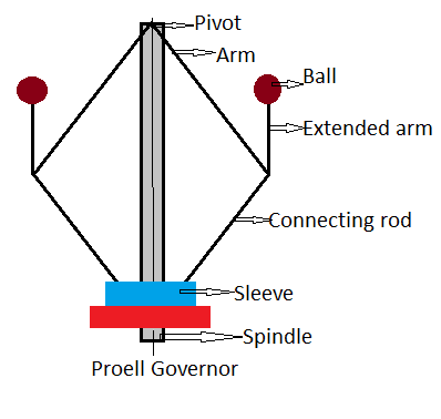
Proel Governor: Proell Governor is a touch unique sort of governor and which an up to date shape of easy centrifugal governor. Proell Governor is a sort of governor carries an moreover prolonged arm that's used to guide the rotating balls established on it. The prolonged arm is attached to the fingers and makes an identical rotational pace at the side of balls established at the prolonged arm and this sort of governor use extra useless weights, which allows to growth the rate of rotation.
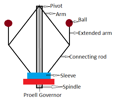
MAIN PARTS OF PROELL GOVERNOR:
- Pivot Arms
- Extended fingers Balls
- Connecting rod:
- Sleeve
- Fuel pump Pivot
This is the factor on the pinnacle cease which connects the fingers.
Arms: This is attached to the balls and makes rotations at the side of the balls.
Extended fingers: This is the directly fingers supplied on the cease of the arm and that is used to guide the balls on it.
Balls: Balls related on the pinnacle of the prolonged arm and the balls have a few detailed weight in line with the software and this allows to transport the sleeve up and down route, via way of means of connecting the cease of the arm to the sleeve with the assist of connecting rod.
Connecting Rod: This is used to attach among the balls and the sleeve.
Sleeve: Sleeve receives related with the balls with the assist of connecting rod to slides at the spindle and which allows to float the gas from gas tank to engine.
Fuel pump: This is used to deliver the gas from the gas tank to the engine while the sleeve movements in an upward route and forestalls while the sleeve reaches the lowest endpoint.
WORKING OF PROEL GOVERNOR:
The running of proel governor is similar to different forms of governors eg: Watt Governor, Hartnell Governor etc. however the creation is little unique When the prolonged fingers rotate at the side of the balls established on it, the sleeve receives moved in an upward route because of the relationship among the arm and the sleeve and the instant of sleeve allows to float the gas from the gas tank
Q12) Write a note on Hartnell governors
A12)
1] Hartnell governor is a kind of spring-loaded centrifugal governor.
2] In Hartnell governor, the downward pressure at the sleeve is carried out via way of spring. This downward pressure may be adjusted via way of making use of compression to the spring via way of adjusting the nut at the body.
3] In this kind of governor, spring is used to use load at the sleeve whilst in different instances lifeless weight is used like in porter and proell governor.
4] In this kind of governor, the imply pace of the engine is adjusted via way of adjusting the burden at the spring.
5] Because of spring, we will modify the imply pace of the engine whilst withinside the case of lifeless-weight-loaded governors it isn't always viable to modify the imply pace.
6] It is smaller in length compared to different governors.
7] Because of the adjustable spring load, the dimensions of flyballs is likewise much less as in comparison to some other governor.
8] As it's far spring-loaded, It doesn’t require gravitational pressure to go back to the preliminary function after reducing of pace. Hence it's far viable to mount it in an willing or horizontal function.
9] Because of the presence of rollers on the sleeve floor it has much less frictional resistance.
Construction:
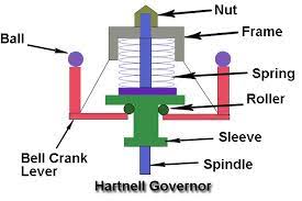
It is includes the subsequent parts:
1] Bell crank lever: The bell crank lever is pivoted to the body. It has a flyball installed at the vertical arm & the horizontal arm is attached to the sleeve.
2] Flyball or Governor ball: These are installed onto the vertical arm of the bell crank lever. The weight of fly balls is relatively decrease than different governors.
3] Spring & Nut: Spring is a helical coil spring this is enclosed into the body. It is used to use downward pressure onto the sleeve. Because of nut & spring, the downward pressure at the sleeve may be adjusted due to this means that the rate of the engine may be adjusted. The nut is installed onto the body to modify the compression of the spring to use load at the sleeve.
4] Sleeve: It is the fundamental issue of the governor this is installed at the spindle of the governor. The horizontal arm of the bell crank lever is attached to the sleeve by a roller. The motion of the sleeve is used to modify the deliver of gas to the engine.
5] Frame:- The body is used to holds bell crank levers & spring. Hartnell governor is a kind of spring-loaded centrifugal governor. It is smaller in creation compared to the lifeless-weight governor.
It includes a bell crank lever, pivoted to the body. It has a flyball installed on a vertical arm & a horizontal arm is inserted into the slot of the sleeve by a roller. The spring is installed onto the spindle among the body & sleeve.
Working:
Case 1: When the burden at the engine will increase
When the burden at the engine will increase, the rate of the engine decreases. Because of the lower in engine pace, centrifugal pressure on flyball decreases. And flyballs are moved inside. Hence load on spring decreases and the duration of the spring extends. It consequences in reducing of the sleeve at the spindle, therefore the delivery of gas to the engine will increase, and the rate of the engine will increase to the imply pace.
Case 2: When the burden at the engine decreases
When the burden at the engine decreases, the rate of the engine will increase. Because of the boom in engine pace, centrifugal pressure on flyball will increase. And flyballs are moved outside. Hence load on spring will increase and the duration of spring decreases. It consequences withinside the upward motion of the sleeve at the spindle, therefore the deliver of gas to the engine decreases, and the rate of the engine decreases to the imply pace.