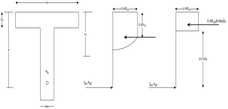
 =1.5 shall be applied in addition to this DIAGRAM Page no 2 Area of stress block=0.36
  Depth of centre of compressive force=0.42
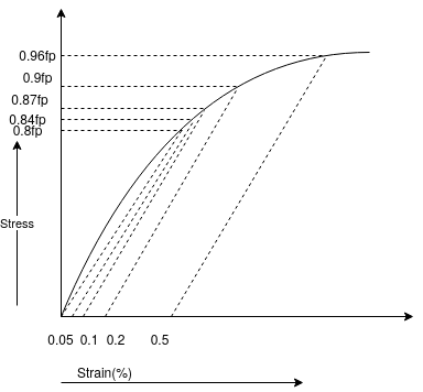
 a) The tensile strength of the concrete is ignored.b) The stresses in bonded prestressing tendons, weather initially tensioned or un tensioned and in additional reinforcement are derived from the representative stress strain curve for the type of Steel used given by the manufacturer or typical curves given in below figure.
|
 equal to 1.15 shall be applied. In addition, the tendon will have an initial prestrain due to prestress after all losses.For members with permanently unbonded internal or externally prestressed tendons, the deformation of the whole member shall be taken into account for calculating strain and stress in the tendon at ultimate condition. In the absence of rigorous analysis, the strain is unbonded tendon shall we assumed not to increase above the initial value due to prestress after all losses. Q2) Draw Stress strain diagram for rectangular section?A2)
|
 should be considered at both conditions, uncracked and cracked in flexure the lesser value taken and if necessary, shear reinforcement provided.Section uncracked in flexure[ IS 1343-2012, Clause no. 23.4.1, Pp-32]The ultimate share resistance of a section uncracked in flexure,
|
 D=overall depth of the member
 =maximum principal tensile stress given by
  taken as positive where
  is the characteristic compressive strength of concrete.
 =compressive stress at centroidal Axis due to prestress taken as positive in placed members where the centroidal axis occurs in the flange, the principal tensile stress should be limited to
  at the intersection of the flanged web ; in this calculation, 0.8 times of the stress due to pressure stress at this intersection may be used, in calculating
  4 section and cracked in flexure and with inclined tendons or vertical prestress, the component of prestressing force normal to the longitudinal axis of the member may be added to
  Q4) Explain the limit state of collapse in shear, the section ucreacked in flexure?A4)
Section crack in flexure [ IS 1343-2012, Clause no. 23.4.2, Pp-33] The ultimate shear resistance of a section cracked in flexure,
Where,
b=breadth of the member, which, for flanged sections, shall be taken as the breadth of the web d=distance from the extreme compression fibre to the centroid of the tendons at the section considered
V and M= shear force and bending moment respectively, at the section due to ultimate loads.
The value of For a section cracked in flexure and with inclined tendons, the component of prestressing force normal to the longitudinal axis of the member should be ignored.
|
When V, the shear force due to the ultimate loads, is less than
Where,
b= breadth of the member which for T, I and L beam should be taken at the breadth of the rib
However, share reinforcement need not be provided in the following cases a) Where V is less than 0.5 b) In members of minor importance When V exceeds
In rectangular beams, at both corners in the tensile zone, a stirrup should pass around a longitudinal bar, a tendon or a group of tendons having a diameter not less than the diameter of the stirrup the depth The spacing of stirrups along member should not exceed |
Concrete grade | M-30 | M-35 | M-40 | M-45 | M-50 | M-55 and over |
Maximum shear stress N/mm² | 3.5 | 3.7 | 4.0 | 4.3 | 4.6 | 4.8 |
IS :1343-2012 Cl No. 19.6.21-a recommends that the permissible stress on concrete, after accounting for all losses due to relaxation of steel, elastic shortening, creep of concrete, sleep in anchorages shall be
Whichever is smaller Where,
- Permissible stress may be increased by 25% at the time of transfer provided the value does not exceed - The effective punching area shall only be the contact area of the anchorage devices which is circular in shape commercial be replaced by a square of equivalent area the bearing area shall be the maximum area of that portion of the member which is geometric li similar and concentric to the effective punching area. - In case of embedded anchorages coma bearing stress shall be investigated after accounting for the surface friction between the anchorage and the concrete. - Where a number of encourages are used, the bearing area shall not overlap, where there is already a compressive stress prevailing over the bearing area comedy total stress shall not exceed the limiting values specified above. - For stage stressing of the cables, the adjacent unstressed anchorages shall be neglected while determining the bearing area. |
|
|
|
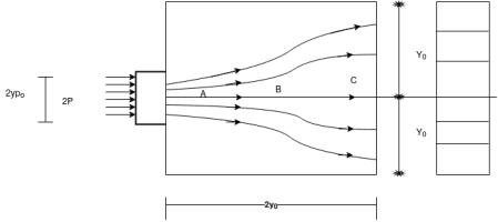
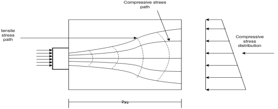
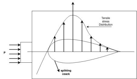
 varying from zero to 0.5 has been investigated by Guyon.
Bursting tensile force[IS 1343-2012, Clause no. 19.6.2.2, pp-26] a) The bursting tensile forces in the end blocks, or reasons of bonded post tensioned members should be assessed on the basis of the tendon jacking load. For unbonded members, the bursting tensile forces should be assessed on the basis of the tendon jacking load or the load in the tendon at the limit state of collapse, whichever is greater. The bursting tensile force,
Where,
b)The force c)when circular anchorage or bearing plates are used, the sides of the equivalent square area should be used. Where groups of anchorages or bearing plates occur, the and blocks should be divided into a series of symmetrically loaded prisms and each prism treated in the above manner. For designing and blocks having a c/s of the beam, reference should be made to specialist literature |
