Back to Study material
SDD3

UNIT 4RETAINING WALL PROBLEMSQ1) State different conditions of stability of Retaining Walls.A1) To ensure the stability of a retaining wall, the following conditions or requirements must be met:
  • The wall should be structurally capable of resisting the pressure applied to it.
  • The wall should be so properly proportioned that it will not get overturned by the lateral pressure.
  • The wall should be safe from consideration of sliding, i.e., the wall should not be pushed out by the lateral pressure.
  • The weight of wall together with the force resulting from the earth pressure acting on it, should not stress its foundation to a value greater than safe bearing capacity of the soil.
  • It is important to prevent accumulation of water behind a retaining wall. The backing material should be suitably drained by providing weep holes.
  • Long masonry retaining walls should be provided with expansion joints located at 6 to 9m apart.
  • Weep holes may be provided to relieve water pressure
  •  Q2) Enlist different loads acting on a Retaining Wall.A2) Major loads that act on retaining walls are as follows.
  • Self weight of retaining wall
  • Vertical earth pressure (on toe and heel of retaining wall)
  • Lateral earth pressure (active, passive or at-rest pressure)
  • Vertical live load
  • Horizontal Live load Surcharge
  • Horizontal Water pressure
  • Buoyancy or Uplift due to water table
  •  Q3) Explain the stability criteria for cantilever retaining wall.7.tifA3)


    6.tif 

    Fig.     Fig.


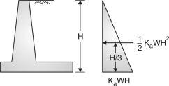
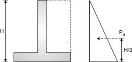
    • Active earth pressure is defined as horizontal pressure exerted by retained earth on retaining wall.
    • Passive earth pressure is defined as the resisting pressure applied by wall on the retained earth.
    • The variation of this earth pressure is linear along the depth of retained earth.
    • The total earth pressure up to the depth H (Fig. 3.4) is the area of pressure diagram which is
      1/2 KaWH2 and acts at a height of H/3 from bottom. Hence, moment due to horizontal pressure = KawH3                        ...(1)

     Where Ka =  and is the angle of repose of soil.

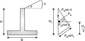
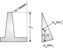
    • 8.tifIn case of a sloping surcharge at an angle to the horizontal pressure at a depth of H1 due to earth = Ka WH1 and total earth pressure up to a depth of H1 = KaWwhich acts at a height of H1/3 and parallel to the ground surface.

    Moment about the base= KaWcos …(2)

     Where, Ka = cos  Fig. 

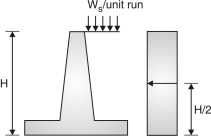
    • If the earth has a level surcharge of ws/unit run, then pressure at all depths is some of magnitude Ka Ws and the surcharge pressure at depth H is Ka Ws H acting at H/2 from bottom (Fig. 3.6)

     Moment due to this at bottom =Ka WH2 …(3)


     Q4) Enlist all the design steps for Cantilever Retaining Wall.A4)

    9.tif 

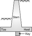
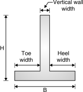
  • The components of cantilever retaining wall are shown in Fig. below.
  • Stem is designed as a cantilever retaining earth.
  • The toe and heel slabs are also designed as cantilevers resisting upward soil pressure and downward earth pressure.
  • The retaining wall is provided with or without shear key at the bottom of the base slab to protect the wall against sliding.
  •  Q5) State the general guidelines to decide the preliminary dimensions of the retaining wall.A5)

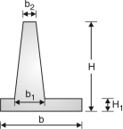
    Following guidelines should be adopted while deciding the dimensions of a cantilever retaining wall :

    10.tif(1) Top width of stem, b2 = 200 mm

    (2) Bottom width – Design for the maximum bending moment.

    (3) Height of retaining wall = H

    (4) Width of base slab = b

    (5) b is usually kept between 0.5 H to 0.6 H for walls without surcharge and 0.7 H for walls with surcharge.

    (6) Toe projection = b/3        

    Fig.

    (7) The thickness of base slab is normally kept as same as the bottom width of stem i.e. b1 = H1

    (8) The wall is to be checked for horizontal sliding. The factor of safety against sliding is > 1.5,

     Where W is total vertical load, is coefficient of friction and p is horizontal earth pressure.

    (9) If necessary, a key is provided.

    The ratio of overturning moment to the restoring moment should be less than 0.87 or the ratio of restoring moment to the overturning moment should be more than 1.15.


     Q6) Write the design steps for a Counterfort Retaining Wall.A6)

    Tentative trial section.  2. Forces

    3. Stability check

     (i) Overturning  (ii) Sliding  (iii) Base pressure


    564. Design of section


     (i) Vertical wall 

     (ii) Toe slab  

     (iii) Heel slab

     (iv) Counter fort

    (I) Trial section :

    1. Base width = 0.6 H to 0.7 H (H = total height of wall)

    2. Toe width =  to   or 

    3. Thickness of vertical walls @ 0.3 m

    4. Counter fort thickness @ 0.4 m

    5. Thickness of base slab = 2l  or 4l

    l  Spacing of  counter fort in m

    H – height in m

     Q7) Show various forces acting on a Counterfort Retaining Wall and equations to calculate.A7)

    57Forces:

    (1)    Horizontal back fill :

    Intensity of earth pressure  = Ka wH

     Ka = Coefficient of active earth pressure.

     Ka  =  

     w  =  unit weight of soil

       = angle of repose Fig. : Pressure distribution diagram (Horizontal backfill)

    Total pressure  =  Ka wH H Pa =    KawH2

    (2) Inclined backfill (with surcharge) :

    58 

    Fig.: Pressure distribution diagram (Inclined backfill)

     Active earth pressure,  Pa   =   Ka w

      Ka = cos

     Where, = angle of surcharge  = angle of repose

    (3) Passive earth pressure : The passive earth pressure is exerted when it has tendancy to move towards the backfill such a case may occur when the retaining wall supports soil of different depths on boths.

     PP = KpwH2  Kp  =  

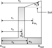
    (4) Self weight of wall

    (i) weight of earth (without surcharge)

     w1 = width height density of soil

    59 x1 = distance of load w1 from toe i.e. (A)

    (ii) weight of earth (with surcharge)

     w2  = Area of triangle density of soil

     x2 = distance of load w2 from A

    (iii) weight of wall

     w3 = Thickness height density of conc.

     x3 = distance of  load w3 from A  

    Fig.:Loads of different parts in retaining wall

    (iv) weight of base slab

     w4  = Thickness width Density of conc

     x4 = distance  of  load w4 from A

     w = w1 + w2 + w3 + w4   M               @ A

     MToe = w1 x1 + w2 x2  + w3 x3 + w4 x4 


     Q8) Explain stability checks for a Counterfort Retaining Wall.A8)

    (i) Check against overturning : (Pg 33, cl-20.1)

    (1) Overturning moment = Pa

    (2) Restoring moment = wx = w1 x1 +w2 x2 + w3x3  .

     0.9 Restoring moment 1.2 overturning moment

     0.9 wx 1.2 Pa ( safe)

    If unsafe change the dimensions

    (ii) Check against sliding :  (clause 20.2)

    (1) Sliding force  = 1.4 Pa

    (2) Restoring force = 0.9 w

    Restoring force sliding force

    0.9 w 1.4 Pa          …Ok

    If it is unsafe there is no need to change the dimensions but provide shear key.

    (iii) Check for base the pressure :

    (1) Maximumpressure = Pmax =

     Eccentricity = e =  – z z = 

     Pmax  S.B.C. of soil

    (2) Maximum pressure = Pmin = 0