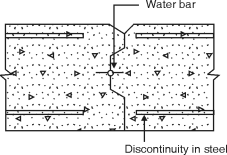
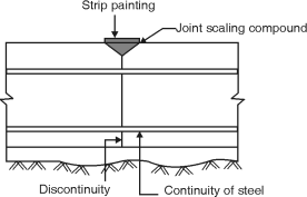
 (a) Movements joints (b) Construction joints (c) Temporary open joints (a) Movements joints : All movement joints are necessarily flexible joints, (i) Contraction joint, (ii) Expansion joint and (iii) Sliding joint(i) Contraction joint :(1) It accommodates contraction of concrete.(2) It may be a complete contraction joint (Fig. (a)) or a partial contraction joint (Fig. (b)).(3) In both cases, initial gap is absent at joint,(4) In complete contraction joint, water bar is inserted.(5) In partial contraction joint, mouth of joint is filled with joint sealing compound.(6) The commonly used materials for joint realing are asphatt, bitumen or coal for pitch with or without fillers.(ii) Expansion joint :(i) It accommodates expansion or contraction of structures.(ii) Initial gap is filled with a joint filler.(iii) Joint fillers are compressible sheet used as spaces.(iii) Sliding joint :(i) It is a movement joint having complete discontinuity in reinforcement as well as concrete.(ii) A special provision is made to facilitate relative movement.
|
|
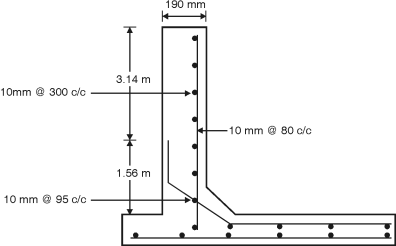
Depth of tank = 4.5 m, Diameter of tank = 8 m Assume a free board of 200 mm Total height of tank H = 4.5 + 0.2 = 4.7 m Unit weight of water = 9.8 kN/m3 Assume M25 concrete and Fe415 steel Permissible tensile stress in steel = 150 N/mm2 = st Permissible tensile stress in concrete = 1.3 N/mm2 cbc = 8.5 N/mm2 Modular ratio, m = = 11 Design constants : n = = = 0.384 j = 1 – = 1 – = 0.872 k = cbc j n = 8.5 0.872 0.384 = 1.423 Design for Cantilever Action :
h = = 1.567 m Cantilever moment = H h = 9.8 4.7 1.567 = 18.85 kN-m. Depth of balanced section d = = = 115 mm Let d = 115 = 153.35 mm Let us provide d = 155 mm and total thickness = 190 mm Ast = = = 929.76 mm2 Using 10 mm bars s = = 80.11 mm = 84.47 mm Provide 10 mm bars @ 80 mm c/c near inner face, keeping a clear cover of 30 mm. Cultural alternate bars at a height of 1.56 m and spacing of 160 mm is available in top 3.14 m height. Design for hoop action : Maximum hoop tension is considered at 1.56 m height. T = (H – h) = 9.8 (4.7 – 1.56) = 123.09 kN Ash = = 820.58 mm2 Using 10 mm bars, Spacing = 1000 = 95.71 mm Provide 10 mm bars @ 95 mm c/c. Check for tensile stress in concrete : Ash = 1000 = 826.73 mm2 ct = = = 0.61N/mm2< 1.3 N/mm2 Hence OK. Provide a spacing of 100 mm for 1.56 m height and 300 mm spacing above 1.56 m height .
|
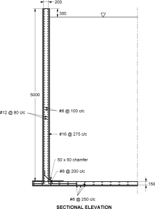
Q5) A cylindrical tank of capacity 7,00,000 litres is resting on good unyielding ground. The depth of tank is limited to 5m. A free board of 300 mm may be provided. The wall and the base slab are cast integrally. Design the tank using M20 concrete and Fe 415 grade steel. Draw the following-Plan at base and Cross section through centre of tank.
A5)Step 1 : Dimension of tank H = 5 – 0.3 = 4.7 and volume V = 700 m3 A = 700/4.7 = 148.94 m2 D = √(4 148.94/) = 13.77 ≫14 m Step 2 : Analysis for hoop tension and bending moment One meter width of the wall is considered and the thickness of the wall is estimated as t = 30H + 50 = 191 mm. The thickness of wall is assumed as 200 mm. Referring to table 9 of IS3370 (part IV), the maximum coefficient for hoop tension = 0.575 Analysis for hoop tension and bending moment (Contd.) Tmax = 0.575 10 4.7 7 = 189.175 kN Referring to table 10 of IS3370 (part IV), the maximum coefficient for Mmax = 0.0146 10 4.73 = 15.15 kN-m Step 3 : Design of section: For M20 concrete σcbc = 7, For Fe415 steel σst = 150 MPa and m=13.33 for M20 concrete and Fe415 steel The design constants are: k = = 0.39 j = 1-(k/3)=0.87 Q = ½ σcbc x j x k = 1.19 Effective depth is calculated as d = = = 112.94 mm Let over all thickness be 200 mm with effective cover 33 mm dprovided=167 mm Ast = = = 695.16 mm2 Spacing of 16 mm diameter bar = = 289.23 mmc/c (Max spacing 3d=501mm) Provide #16@275 c/c as vertical reinforcement on water face
Hoop steel : Ast1 = = = 1261 mm2 Spacing of 12 mm diameter bar = = 89 mmc/c Provide #12@80 c/c as hoop reinforcement on water face Actual area of steel provided Ast = 1412.5 mm2 Step 4 : Check for tensile stress: c = = = 0.87 N/mm2 Permissible stress = 0.27√fck=1.2 N/mm2>c Safe Step 5 : Distribution Steel: Minimum area of steel is 0.24% of concrete area Ast = (0.24/100) 1000 200 = 480 mm2 Spacing of 8 mm diameter bar = = 104.7 mmc/c Provide #8 @ 100 c/c as vertical and horizontal distribution on the outer face. The thickness of base slab shall be 150 mm. The base slab rests on firm ground, hence only minimum reinforcement is provided. Ast = (0.24/100) 1000 150 = 360 mm2 Reinforcement for each face = 180 mm2 Spacing of 8 mm diameter bar = = 279 mmc/c Provide #8 @ 250 c/c as vertical and horizontal distribution on the outer face.
|
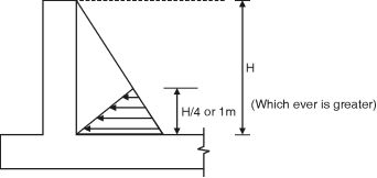
The exact analysis of rectangular water tank is difficult and the design cab be done by approximate method as per is IS3370. Two cases are considered for rectangular water tank. 1. When <2 : In this case the tank walls are assumed to cantilever continuous frame subjected to hydrostatic pressure. The bottom or 1 m (which is greater) is designed as cantilever and the top portion of a continuous frame in which moments are calculated by moment distribution. In addition to the walls are subjected to direct tension due to hydrostatic pressure. The direct tension in long wall : Specific weight of water = w (H h) × B The direct tension in short wall = × L
2. If >2 :
P = × wH × H BM= × wH × H × = The maximum BM at the junction of steel and long wall = B2Fig. 5.7.2 Maximum positive BM at the centre of short wall = The maximum BM for the bottom of short wall = or Direct tension in long wall = direct tension in short wall =
|
Q7) A rectangular water tank open at the top is to be provided at the ground level to accommodate 45 kl of water. The depth of water is to be about 3 m with FB of 0.2. The ratio of length of longer to shorter side of tank is limited to 1.25. Design the tank assuming M20 and Fe250.
A7)Given : Capacity = 45 kl 1 kl = 1 m3 = 45 m3 Depth of water = 3m Free board = 0.2 m Height of tank = 3 + 0.2 = 3.2 m Volume = L B H 45 = L B 3.2
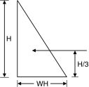
= 1.25 B L = 1.25 B 1.25 B B = 14.06 B = 3.35 m 3.5 m Fig. P. 5.7.1 Intensity of pressure at 1 m from base = w H = 10 2 = 20 kN/m2 For 1 m depth of wall = 10 1 = 10 kN/m2
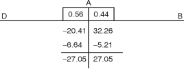
Moment distribution :
= = = 32.26kN/m w-at 1 m from base = – = = – 20.41
Maximum simply supported BM for longer span = = = 48.4 kN.m Net BM = 48.4 – 27.06 At centre = 21.34kN.m For shorter span : Maximum S. S. BM = = = 30.625 kN.m Net BM at centre = 30.625 – 27.06 = 3.57 kN.m The pull in longer wall = TL = = = 35 kN
Fig. P. 5.7.1(B) Pull in short wall = = = 44 kN Thickness of wall : 1. Minimum thickness = 100 mm 2. (30 mm per meter depth of water) + 50 = (30 3) + 50 = 140 mm 3. 60 mm per meter length of water = 60 4.4 = 264 mm Take greater value = 264 mm Assume t = 300 mm
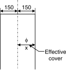
x = Eccentricity of T x = 150 – Efficiency cover = 150 – 40 = 110 mm = 0.11 m
Efficiency cover = Clear cover + = 30 + = 40 mm For longer wall Net BM = M – TL x (at mid span) = 21.35 – 35 0.11 = 17.50 kN.m And at junction = M – TL x = 27.06 – 35 0.11 = 23.2 kN.m For shorter wall Net BM= m – TB x (mid span) = 3.57 – 44 0.11 = – 1.27 kN.m Negative sign indicate tension on water face At junction = M – TB x = 27.06 – 44 0.11 = 22.22 kN.m
Check for depth : M = f Z f = cbt for M20 cbt= 1.7 N/mm2 Z = b =1000 mm = 1 m Mr = D = t = ? Equating maximum BM to Mr Maximum BM = 23.2 106 N.mm 23.2 106 = D = 286 < 300 mm …OK Assuming D = 300 mm d = 300 – 30 – = 260 mm
Area of steel at junction : 1. Ast in shorter wall at junction Ast = + = + = 1236.9 mm2 For Fe 250st = 115 N/mm2 M20 and Fe 255 J = 0.87 Ast(read) in long wall at junction Ast = + = + = 1207.74 mm2 (1211.5) Ast (min) :
Ast min = 0.24 % of Ag = 1000 D = 1000 300 = 720 mm2 Fig. P. 5.7.1(D) Assuming 16 mm bars Spacing = = 162 = 160 mm c/c Providing 16 mm bar at the spacing 160 mm c/c horizontally. In the depth from 1 m up to 2 m above the base at the junction in the long and short wall for a distance 0.25 l from the support. Since the water pressure decreasing towards the top area of steel above 2 m from base = = 618 mm2 Ast (min). = 720 mm2. Assuming 12 mm bar Spacing= 150 mm c/c Providing 12 mm bar @ 150 mm c/c in the top 1.2 m height of the wall. Ast in centre of span : 1. In shorter wall : Ast = + = + = 431.62 < Ast (min) Provide Ast = 720 mm2 Providing 12 mm bars Spacing = = 150 mm c/c Providing 12 mm bars @ 150 mm c/c 2. Longer wall : Ast = + = + = 977.08 < Ast (min) Assuming 16 mm bars Spacing = 200 mm c/c Distribution steel (Ast)min = 1000 D = 1000 300 = 720 mm2 On each face = = 360 mm2 Assuming 8 mm bar Spacing = = 130 mm c/c Design of bottom 1 m height : Pressure intensity at base = wH = 10 3 = 30 kN/m2 Cantilever moment at the base
Ast = = = 192.21 < Ast (min) Fig. P. 5.7.1(E) Provide Ast = 720 mm2 Steel on each face = = 360 mm2 Providing 10 mm @ 210 mm c/c on both faces. Base slab : The water tank is resting on ground providing 150 mm thick slab. Ast = 0.3 % of Ag = 1000 150 = 450 mm2 On each face = = 225 mm2 Assume 8 mm bars Spacing = 220 mm c/c
|
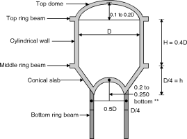
(1) Height to diameter ratio = 0.4 (2) Around 10% of total capacity is because of bottom conical portion. Hence the capacity of vertical container can be equivated with 90% of capacity to have H and D. (3) Diameter of top dome = diameter of container. (4) Risk of top dome is 0.1 to 0.2 time dia. (5) Height of conical dome = rise of top dome. It can be equal to
Bottom dome : It is approximately 50% m diameter compare to diameter of top dome. Rise of bottom dame is kept somewhat greater approximately 20 to 25% of bottom dome diameter. Volume of tank (1) Capacity of cylindrical portion = D2H (2) Capacity of Bottom conical dome = Fig. A Typical Intze tank
(3) Capacity of bottom dome = (3r2 + h2) h (4) Total capacity = (1) + (2) – (3) |
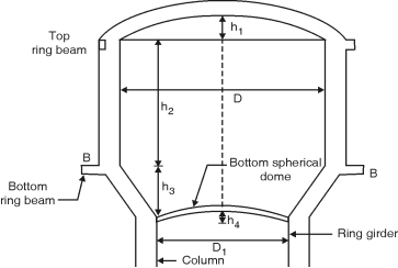
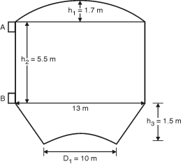
Capacity of tank=1000 k J = 1000 103liters = 1000 m3 cbc = 8.5 N/mm2, st = 150 N/mm2 , m = 11 ct = 1.3 N/mm2, cc = 6 n/mm2, n = 0.384, j = 0.872 K = 1.423 Dimensions of tank : Let the diameter of cylindrical portion=D Diameter of bottom ring girder =0.6D Height of conical shell h3= 0.2D Height of bottom spherical dome= The volume of tank V = Volume of cylindrical portion + Volume of conical portion – Volume of bottom spherical dome portion = D2 h2 + h3 – (3R2 – h4) D1 = 0.6D, h2 = 0.4D, h3 = 0.2D, h4 = Radius of bottom dome R2 is = 0.36 = 0.09D2 R2 = 0.386 D V = D2 0.4D + (D2 + 0.36D2 + 0.6D2) = 0.374 D3 0.374 D3 = 1000 D = 13.88 m Let D = 14 m, D1 = 0.6D = 0.6 14 = 8.5 m h2 = 0.4D = 0.4 14 = 5.5 m h3 = 0.2D = 2.8 m h4 = = 2 m Actual volume of tank 2 (2R2 – 2) = R2 = 5.52 m V = 142 5.5 + 2.8 (142 + 8.52 + 14 8.5) – 22 (3 5.52 – 2) = 1069 m3
|
Fig. ** Design of Top dome : Diameter = 13 m Let rise = 1/7 13 = 1.86 m Radius of spherical dome – 2 (2R1 – 2) = 6.52 R1 = 11.56 m Semi-central angle = cos– 1= 34.21 Let the thickness of dome= 75 mm Self weight = 0.075 1 1 25 = 1.875 kN/m2 Live load = 1.5 kN/m2 Total = 3.375 kN/m2 4 kN/m2 Meridoinal thrust T1 = w R1= = 25.31 kN/m Meridoinal stress = = 0.34 N/mm2< 6 N/mm2 O.K. Circumferential force = T2 = wR1 = 4 11.56 = 12.93 kN/m Circumferential stress= = 0.172 N/mm2 < 6 N/mm2 O.K. Provide nominal reinforcement of 0.3 % in circumferential and radial direction. Ast = 75 1000 = 225 mm2 Using 8mm bars, S = 1000 = 223 mm Provide 8mm bars at 200 mm c/c in radial and circumferential directions. Design of Top Ring (Beam A–A) : Hoop tension = T1 cos = 25.31 cos 34.21 = 136.05 kN Ast = = 907mm2 Provide 5 bars of 16mm diameter Astprovided = 5 162 = 1005.31 mm2 Area of concrete : 1.3 = = Ac = 93595.44 mm2 Assume b = 300mm Provide 300 350 mm top ring beam with 5 bars of 16mm (2 at top and 3at bottom). Also provide nominal shear reinforcement of 6mm bars @ 300mm c/c. Design of side wall : Hoop tension at base of tank = 9.8 5.5 = 350.35 kN Ast = = 2335.67 mm2 Use 16 mm bars on each face s = 1000= 172.16 mm Provide 16 mm bars on each face @ 170 mm c/c Ast provided = 2 162 = 2680 mm2/m height Area of concrete : 1.3 = = Ac = 240020 mm2 /m height t = = 240.02 mm Provide t = 250 mm Distribution steel : P = 0.3 – 0.1 = 0.25 Area of distribution steel required = 275 1000 = 687.5 mm2 Area of distribution steel required on each face = 687.5/2 = 343.75 mm2. Use 8 mm bars. S = 1000 = 146 mm Provide 8 mm bars@ 140 mm c/c on each face. Hoop tension = 9.8 3.5 = 222.95 kN/m Ast = = 1486.33 mm2 Aston each face = 743.17 mm2 Use 12 mm bars S = 1000 = 152.18 mm Use 12 mm bars @ 150 mm c/c on each face. |
