Back to Study material
SDD3

UNIT 6Q1) Define degree of freedom.A1) Definition:-The member of independent coordinates required to describe the position of A vibrating mass are termed as degree of freedom of that mass. Q2) Explain the concept of single degree of freedom system.A2) When a mass is vibrating its position in space with repeat to its equilibrium position can be described by fixed to ordinates:-Three translational along three orthogonal axes x ,y ,z .Three rotational about some axis. 

 Σfx=0,       Σfy=0,                Σfx=0Σmx=0, Σmy=0,              Σmz=0 
  • However a mass may have freedom to move only in certain direction and may be constructed in other direction.
  •  2.     If a system is represented by single mass and it is constrained such that its motion is described by a single to ordinates it is termed as a single degree of freedom system.

     Q3)   Write equation for motion of single degree of freedom system and write the meaning of terms in it.

    A3) Let's consider a mass M attached to a fixed frame a b through a spring shown in figure 1 on an elastic system such as represented by forcewhich is a function of time and let the displacement be equal to X at any time t. 
  • The velocity and acceleration of the mass at some time would be x and x respectively taking positive in the positive direction of sx.
  • Besides the exciting force FCT) the forces rating on the mass would be inertia force (Mx) spring force (kx) where,
  • K=storing force of that spring or elasticity of the portal frame which exerts for unit displacement and damping force (CX) whereC= coefficient of viscous damping in terms of force per unit velocity.3.     It should be seen that if the displacement X is towards right the spring force (kx) on the mass is edging towards left and is described by –ve sign.4.     Similarly damping force acts against the direction of velocity and would thus be acting towards left.5.     Considering FBD ab to mass the force is acting on it r are.F(F) =kx - cx

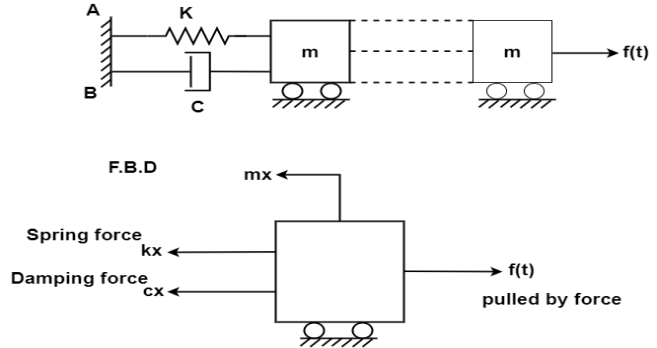
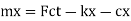
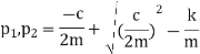
    By newton's second law of motion these forces are equal to mx


         Distance= velocity* time

    Velocity/speed=

    Retardation =-ve sign indicate opposite direction of displacement


     Q4) Explain Damped single degree of freedom system under free vibrationA4) Forces designated as frictional  damping force are always present in any physical system undergoing these forces dissipate energy more precisely the under presence of these frictional forces constitutes through which the mechanical energy of the system kinetic and potential energy of the system is transferred to other forms of energy such as heat. The stamping of friction forces proportional to the magnitude of velocity and off to the direction of motion this type of damping is known as viscous damping.

    K= spring constant C= damping coefficient 

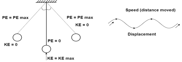
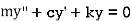
    Using D'Alembert’s principle we can write equation of equilibrium to obtain equation of motion.

    Summation of forces in y direction

    -----------1


    Solution of differential equation 1 is


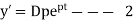
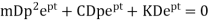
    Substitute 2 in 1 we get

    ----------------3

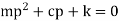
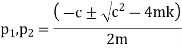
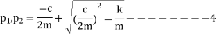
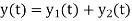
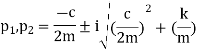
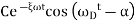
    Thus the general solution of equation 1 is given superposition of the two possible solutions namely.
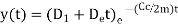
    Where

    The final solution form of equation V depends on the sign the expression under the radical in equation 4.

    Three distant cases may occur.

    • Quantity under the radical may be zero=critical damping
    • The quantity under the radical male positive=overdamped.
    • The quantity under the radical may negative=underdamped
     Q5) Write the equation for critically damped system and explain the concept.A5)

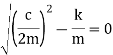
    The limiting case in which the quantity under radical is zero the damping present in this case is called critical damping.


    This means that the expression under root of equation 4 in equal to zero

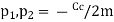
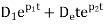
    Cc= 2mw

    In critically damped system the roots of characteristic equation are equal and from equation 4.

    Since the roots are equal the general solution given by equation 5 would provide only one independent constant integration, hence


    The general solution for the critically damped system is then given by the superposition of these two solutions

    We know that,


    =

     Q6) Write a short note on over-damped system.In and overdamped system the damping coefficient is greater than the value of critical damping i.e. C>Cc also A6)

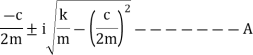
    Expression in the radical of equation 4 thus the solution is


    Q7) Explain Under-Damped system in short.A7)

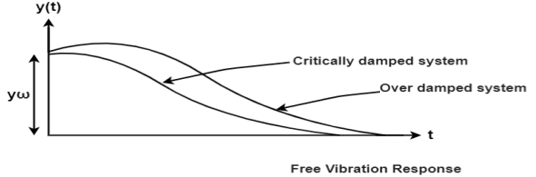
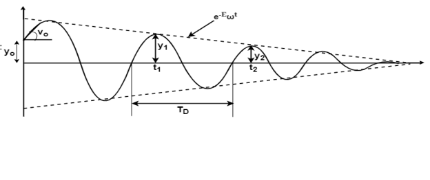
    In case of underdamped system damping coefficient is less than critical value C<Cc, which occurs when the expression on the radical of equation 4 is negative.
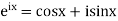
    Where i=imaginary unit

    For this case, we use Euler’s equation which relates exponential and trigonometric functions.  Namely,

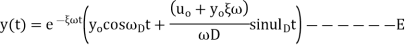
    Substitute A in equation 5 ,we get

    ---------C


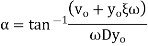
    Finally when the initial conditions for displacement find velocity
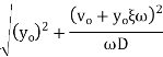
Are introduced the constant of integration can evaluated and substituted in equation X we get,


    Where


    C= max. Amplitude


     Q8) Explain Primary waves, Secondary waves and Surface waves.A8)Primary waves are also known as push-pull waves are longitudinal waves compressional waves these waves propagate by longitudinal or compressive action grounds get alternately compressed and dilated in the direction of propagation.Secondary waves are also called transverse waves. In comparison to P- waves, s -waves are slow. Because of the waves, ground gets displays perpendicularly to the direction of propagation.When the vibrator waves energy is propagating near the surface of the earth, two other types of wave known as Rayleigh and fav can be identified these are known as surface waves as they are confined to the surface layers of the earth only. Q9) Explain step by step procedure for calculation of base shear as per IS:1893.A9)

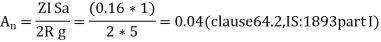
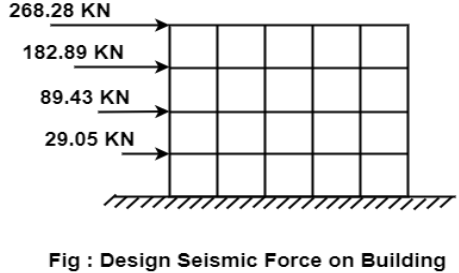
    Use of systemic coefficient method As given inIS:-1893 can be carried out to compute forces and moments in the member.

    This method design base is calculated from


    Where,     = Design horizontal acceleration spectrum


    Where Z=zonal factor given in IS:-1893 ,

     Table 2:-

     Value Z


    zone

    Value of z

    2

    o.10

    3

    0.16

    4

    0.24

    5

    0.36


    I= important factor depending on the functional use of structure (table 6 of IS:-1893) I=1 and 1.50


    R=Response reduction factor depending on Pereceivedsiesmic damage performance of structure (Table-7, IS:-1893).


    R= 3 to 5 for movement resistant RC structures.

    = Average response acceleration coefficient is given bye figure 2 and table 3 of IS:-1893.

    W= seismic waves of the building


    The seismic weight of the whole building is the sum of the systemic weights of all the floors and will include 25% and 50% of L.L.for floors in case of LL limit upto3 kN/m and above 3 kN/m and L.L on roof is to be considered.


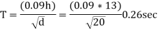
    Sa/g values are obtained on the basic of fundamental/ natural/period of vibration.

    For moment resistant buildings with brick fell,

    Where,h= height of building excluding basement story

    d=best dimensions of building at plinth level along the considered direction of lateral forces.

    For moment resistant building without brick fills.

    Periodfor R.C framed building


    Values of Sa/g based on 5% damping


    Types of soil

    Sa/g values

    Rocky or hard  soil

    1+IST for 0.00

    2.50 for 0.10

    100/T for 0.40

    Medium soil sites

    1715 T for 0.00 0

    2,50 for 0.10

    1.36/T for 0.55

    Soft soil sites

    1715T for 0.00<=T<=0.10

    2.50 for 0.10<=T <=0.60

    1.67/7 for 0.60 <=T<=4.00


    Multiplication factors

    3.20

    1.40

    1.00

    0.50

    0.80

    0.70

    0.60

    0.55

    0.50

    Damping %

    0

    2

    5

    7

    10

    15

    20

    25

    30


    Design base sheer shall be distributed as nodal loads on different floors

    Design lateral bed on floor

    Seismetic wt of floor

    height of floor I measured  from base


     Q10) A four storey building has the following dataOverall plant dimensions=20m×16mNumber of  boys 4m each in X direction=5Number of boys 4m each in y direction=4First storey height=4mHeight of 2nd,3rd ,4thstorey=3mSize of beams=300mm×600mmSize of columns=150mmLive load=3.5Kn/m on floors and 2Kn/m on roofExternal missionary walls of the thickness 230 mm and internal walls of 115 mm thickness have been provided.Building located in Pune on hard strata with 5% damping evaluate the specific weight of each floor and hence total seismic weight of building calculate the base shear using seismic coefficient method.

    A10)


    1. Pune location, zone-3 ,Z=0.16( Table 2, IS:-1893)

    From table 6 important factor I=1(all other buildings).

    Assume the building as special moment resisting frame.

    Response reduction factor R=5(Table 7, IS:-1893)


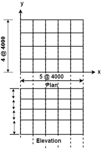
    2.     Seismic weight:-

    floor area=20×16=320m

    Assume DL=10Kn/m

    Total seismic weight on floors

    Roof:-

    Total seismic weight of the structure W=ΣWi=3*3680+3200

    14240KN

    3.     Fundamental period:-

    Lateral load resistance is provided by moment resisting frames infilled with brick marnry panels

    From figure 2 of IS: 1893 part I , for T =0.26 sec

    Sa/g=2.5


    4.     Design base shear:-

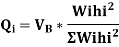
    The design base shear is to be distributed with height as per class 7.71 , IS: 1893m part I


    Storey hard

    Wi

    hi (m)

    4

    3200

    18

    540.8

    0.471

    268.28

    3

    3680

    10

    368

    0.321

    182.84

    2

    3680

    7

    180.32

    0.157

    89.43

    1

    3680

    4

    58.88

    0.051

    29.05


    1148

    1000

    569.60