UNIT 4
Laminar & Turbulent flow through pipes
Q1. Explain Characteristic of Laminar Flow with examples.
Ans- Characteristic of Laminar Flow
Laminar is characterized by smooth streamlines and highly ordered motion. Under most practical conditions, the flow in a circular pipe is laminar for Re < 2000.
In fully developed laminar flow, each fluid particle moves at a constant axial velocity along a streamline and the velocity profile remains unchanged in the flow direction.
The steady laminar flow of an incompressible fluid with constant properties in the fully developed region of a straight circular pipe.
Laminar flow in a straight pipe may be considered as the relative motion of a set of concentric cylinders of fluid, the outside one fixed at the pipe wall and the others moving at increasing speeds as the center of the pipe is approached.
Smoke rising in a straight path from a cigarette is undergoing laminar flow. After rising a small distance, the smoke usually changes to turbulent flow, as it eddies and swirls from its regular path.
Examples
Laminar flow is common only in cases in which the flow channel is relatively small, the fluid is moving slowly, and its viscosity is relatively high.
Oil flow through a thin tube or blood flow through capillaries is laminar.
Most other Kinds of fluid flow are turbulent except near solid boundaries, where the flow is often laminar, especially in a thin layer just adjacent to the surface
Q2. Explain Hagen Poiseuille equation for Laminar flow through a circular pipe.
Ans-
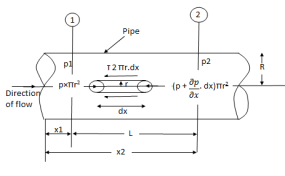
Fig: Shows a horizontal circular pipe of radius R, having the laminar flow of fluid through it.
Consider a small concentric cylinder of radius r and length dx as a free body.
If  is the shear stress, the shear force F is given by
F =  x 2
x 2  r x dx
Let P be the intensity of pressure at left end and the intensity of pressure at the right end be (
Thus, the force acting on the fluid element is:
i) the shear force,  x 2
x 2 r x dx on the surface of a fluid element.
ii) The pressure force, P x  on the left end.
iii) The pressure force, ( on the right end.
For steady flow, the net force on the cylinder must be zero.
 [ p x
[ p x  - (
- ( ] –
] – 
 -
-  -
-

Shear stress is zero at the center of pipe (r = 0) and maximum at the pipe wall given by
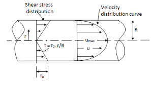
 (
( )
)
From Newton’s Law of viscosity.

In this equation, the distance y is measured from the boundary. The radial distance r is related to distance y by the relation.
y = R-r or dy = -dr

Comparing two values of 
 =
= 
 du =
du =  (
( )r.dr
)r.dr
Integrating the above equation w. r. t. ‘r’ we get
 u =
u =  .
.  r2 + C --------------- (ii)
Where C is the constant of integration and its value is obtained from the boundary conditions.
At r = R, u = 0
 0 =
0 =  .
.  R2 + Cor C =
  .
.  R2
R2
Substituting this value of C in eqn. (ii) we get,
 u =
u =  .
.  r2
r2 .
.  R2
R2
 u = -
u = -  .
.  (R2 – r2)
Shows that the velocity distribution curve is a parabola.
The maximum velocity occurs, at the center and is given by.
 umax = -
  R2
R2
Q3. Explain Characteristics of turbulent flow.
Ans-
The instantaneous velocity at the given point can be expressed as
u =  + u’
+ u’
u = instantaneous velocity
 = time average for temporal mean velocity and
u' = velocity fluctuation (fluctuating component)
Similarly, v =  +v’
+v’
w =  + w’
+ w’
And p = + p’
+ p’
From the definition of average velocity is we have,


where T = large interval of time.
The magnitude of Turbulence = Arithmetic means of root means the square value of turbulent fluctuations in the three directions.

Intensity of turbulence

Where  = Line average resultant velocity at that point.
Q4. Define Instantaneous velocity& temporal mean velocity.
Ans- Instantaneous Velocity:
Temporal Mean Velocity:

Q5. Explain Scale of turbulence & intensity of turbulence .
Ans- Scale of turbulence


Intensity of turbulence

Where  &
& are the fluctuations of the velocity vector components
 = Line average resultant velocity at that point.
Q6. Explain Prandtl’s mixing length theory .
Ans- According to Prandtl, the mixing length (l) is defined as the average lateral distance through which a small mass of fluid particles would move from one layer to the other adjacent layers before acquiring the velocity of the new layer.
He assumed that components u' and v' are of the same order and the velocity fluctuation in the x-direction is related to the mixing length as


When the viscous action is also included, the total shear stress may be expressed as

Above equation is used for most of the turbulent flow problems for determining the shear stress.
Q7. Explain Velocity Distribution for Turbulent Flow in Smooth Pipes.
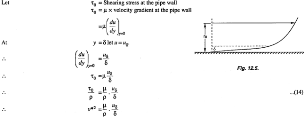
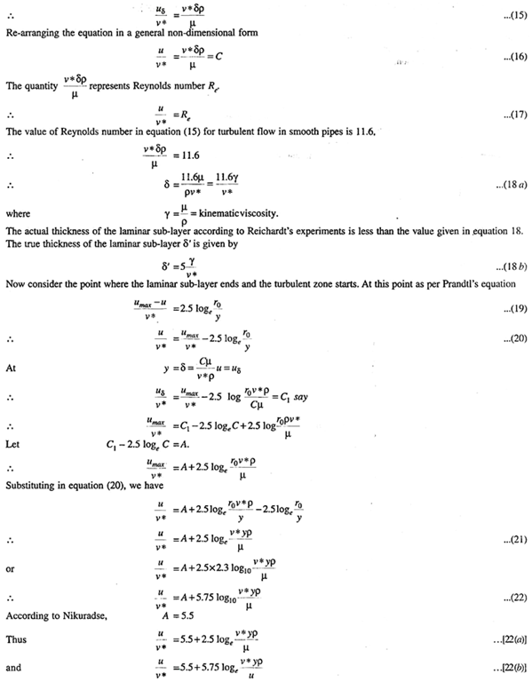
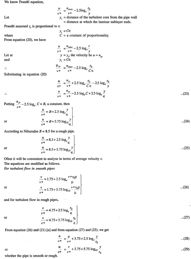
Ans- Prandtl’s universal velocity distribution equation is valid in the central region of the pipe where the turbulent flow is fully developed. But in the regions close to the pipe wall the flow is not fully turbulent, and is more close to laminar flow. There exists a distance  from the surface of the wall up to which the velocity varies linearly as shown in fig.
This thickness is the thickness of the laminar sub-layer and is very small compared with the pipe radius r0.
Q9. Explain Variation of friction factor for laminar flow and turbulent flow.
Ans- Variation of friction factor f for laminar flow
The friction of factor f for laminar flow in pipes is given by

The equation shows that for laminar flow the friction factor F varies inversely with Re and it is independent of K/D ratio.
Variation of friction factor f for turbulent flow
For the fully developed turbulent flow, the friction factor F is a function of Re or K/D ratio or both, depending on whether the boundary is hydro dynamically smooth or rough or it is in transition.
Q10. Explain Variation of friction coefficient f for smooth pipe and rough pipes.
Ans- Variation of friction coefficient f for smooth pipe-


Nikuradse’s experimental result for turbulent flow in smooth pipe For Re = 5×10⁴ to Re as high as 4 × 10⁷ for f is

f = 
Variation of friction coefficient f for rough pipes-


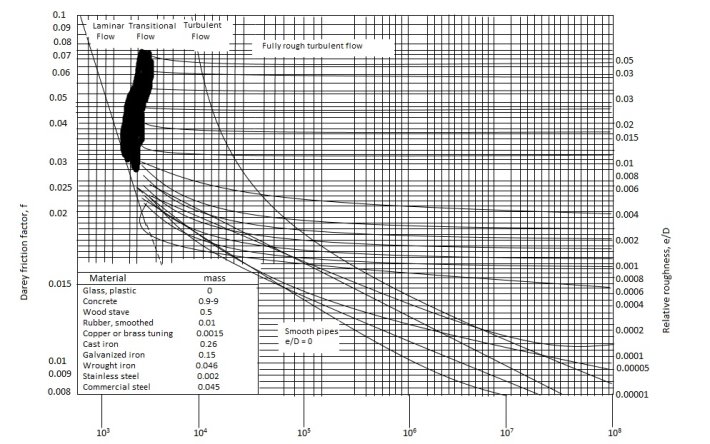
Q11. Explain in detail Moody’s Diagram.
Ans- Moody’s Diagram


Q12. Explain Flow through pipes such as series & parallel.
Ans- Pipes in series
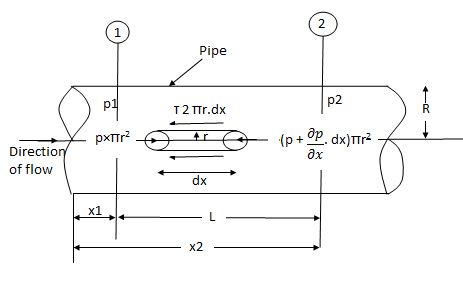
L1, L2,L3 = Length of pipes 1, 2 and 3 respectively
d1, d2, d3 = diameters of pipes 1, 2, 3 respectively
v1, v2, v3 = velocity of flow through pipes 1, 2, 3
f1, f2, f3 = coefficients of frictions for pipes 1, 2, 3
H = difference of water level in the two tanks
The discharge passing through each pipe is the same


The difference in liquid surface levels is equal to the sum of the total head loss in the pipes.

If minor losses are neglected, then the above equation becomes as

Pipe in parallel
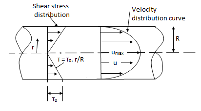

In this arrangement, the loss of head for each branch pipe is the same.
Hence, Loss of head for branch pipe 1 = Loss of head of the branch pipe 2

Q13. Explain Dupuit’s Equation.
Ans- Equivalent pipe
L1= length of pipe 1 and d1 = diameter of pipe 1
L2 = length of pipe 2 and d2 = diameter of pipe 2
L3 = length of pipe 3 and d3 = diameter of pipe 3
H = total head loss
L = length of equivalent pipe
d = diameter of equivalent pipe
Total head loss in the compound pipe, neglecting minor losses
 --------- 1
f1 = f2 = f3 = f


Substituting these values in equation 1, we have

 --------- 2
Head loss in the equivalent pipe, 
Where 
 --------- 3
Head loss in the compound pipe and the equivalent pipe is same hence equating equations 2 and 3, we have

or 
 --------- 4
Equation 4 is known as the Dupuit equation
Q14. Explain Pipe network analysis by Hardy Cross method.
Ans- This method is applicable to closed-loop pipe networks. The outflows from the system are assumed to occur at the nodes, where a node is the end of each pipe. This assumption would therefore result uniform flow in the pipelines distribution systems.
The Hardy-Cross analysis is based on the principles that

2. Head balance criterion: algebraic sum of the head losses around any closed-loop is zero.

For a given pipe system, with known junction outflows, the Hardy-Cross method is an iterative procedure based on initially estimated flows in pipes. Estimated pipe flows are corrected with iteration until head losses in the clockwise direction and in the anticlockwise direction are equal within each loop.
2. With the assumed value of Q, the head loss in each pipe is calculated according to the equation

Where
 : Head loss
r: head loss per unit flow
n: flow exponent
3. The net head loss around each loop is calculated.
4. If the net head loss due to assumed values of Q round the loop is zero, then the assumed values of Q in that loop are correct. If this is not the case, then the assumed values of Q are corrected by including a correction ï„Q for the flows till the circuit is balanced.
5. The correction factor ï„Q is obtained by

6. For turbulent flow, the value of n=2 and hence the correction factor becomes

7. If the value of ï„Q is positive, then it is added to the flow in the clockwise direction and subtracted from the flows in the anticlockwise direction.
8. After the corrections have been applied to each pipe in a loop and to all loops, a second trial calculation is made for all loops. This procedure is repeated till ï„Q becomes negligible.
Q15. Determine the wall shearing stress in a pipe of diameter 100mm which carries water. The velocities are at the pipe center and 30m from the pipe center are 2m/s and 1.5 m/s respectively. The flow in the pipe is given as turbulent. Find  0.
0.
Ans.
D = 0.1m R = D/2 = 0.05m
Umax = 1.5 m/s


Q16. In a pipe of diameter 300 mm and Centreline velocity and velocity at a point 100mm from the centreline as measured by pitot tube are 2.4 m/s and 2 m / s respectively. Assume the flow in a pipe to be turbulent, find i) discharge through the pipe
ii) coefficient of friction
iii) height of replenishes projections.
Ans. D=0.3m R=D/2=0.15m Q=? f=? k=?
Umax = 2.4 m/s u=2m/s


u* = 0.146m/s

At y=R, u=umax

 log10 (1) = 0
 =1.85 m/s
Q=A× =
= 


f=0.0124


Q17. A horizontal pipeline 40 m long is connected to a water tank at one end and discharges freely into the atmosphere to the other end. For the first 25 m of its length from the tank, the pipe is 150 mm diameter, and the diameter is suddenly enlarged to 300 mm. The height of the water level in the tank is 8 m above the center of the pipe. Considering all losses. Find the rate of flow. Take f = 0.01 for both pipes.
Ans –
Given L = 40 m
L1 = 25 m
L2 = 15 m
d1 = 0.15 m
d2 = 0.3 m
H= 8 m
f = 0.01
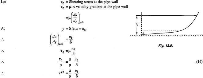
A1 = 

By continuity equation
A1V1 = A2V2
V1 = 
Find Q.
Apply Bernoulli’s Theorem to the free surface of the water in the tank and outlet of the pipe.


 -------- 1
Hf = Head loss of inlet + Major loss in pipe 1 + Head loss due to sudden enlargement + Major loss in pipe 2


Put in equation 1


Q18. A siphon of diameter 200 mm connects two reservoirs having a difference in elevation of 20 m. The length of the siphon is 500 m and the summit is 3 m above the water level in the upper reservoir. The length of the pipe from the upper reservoir to the summit is 100 m. Determine the discharge through the siphon. Neglect minor losses. Take f = 0.005 m.
Ans-
Given
d = 0.2 m
H= 20 m
L = 500 m
h = 3 m
L1 = 100 m
f = 0.005
find Q, 
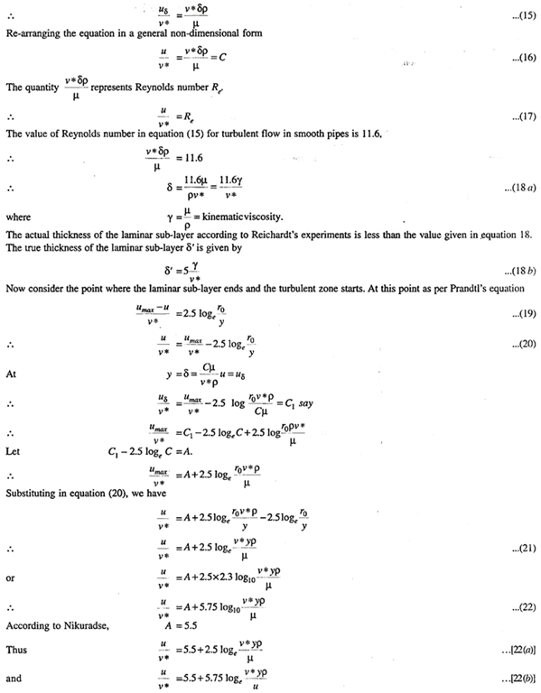
Apply Bernoulli’s equation to point A and B


Apply Bernoulli’s equation to point A and C


Q19. Three pipes of 400 mm, 200 mm and 300 mm diameters have lengths of 400 m, 200 m and 300 m are connected in series to join two water tanks having level difference of 16 m. If coefficient of friction is same and equal to 0.005. Determine discharge first neglecting minor losses and the including them.
Ans. Given
H = 16 m
L1 = 400 m
L2 = 200 m
L3 = 300 m
d1 = 0.4 m
d2 = 0.2 m
d3 = 0.3 m
f1 = f2 = f3 = 0.005


By continuity equation
A1V1 = A2V2
V2 = 


Now, Case 1: Neglecting minor losses


Case 2: Minor losses considered
H = Loss at entry + Major loss1 + Loss due to sudden contraction + Major loss 2 + Loss due to sudden enlargement + Major loss 3 + Loss at exit


Q20. An old water supply system pipe of 250 mm diameter of a city is to be replaced by two parallel pipes of smaller equal diameter having the equal length and identical friction factor values. Find out the new diameter required.
Ans.
D= diameter of each parallel pipes = 0.25 m
Q = Discharge in old pipe
Q1 and Q2 = Discharge in first and second parallel pipe
Hf = hf1 = hf2
Q = Q1 + Q2
As the diameter is the same for both parallel pipes


But hf = hf1


Q21. A 300 mm long pipeline is used for transmission of power. 130kW power is to be transmitted through the pipe in which water having a pressure of 40 bar at the inlet is flowing. If pressure drop over the length of the pipe is 500kN/m2 and f=0.024. Find i) Diameter of pipe ii) Efficiency of transmission.
Ans.
Given
L = 3000 m
Power = 130 × 103 watts
P = 40 bar = 40 × 105 N/m2
Pressure drop = 800 kN/m2 = 800 × 103 N/m2
f = 0.024


Q22. A farmer wishes to connect two pipes of different lengths and diameters to a common header supplied with 8 ×10⁻³m3/s of water from a pump. One pipe is 100 m long and 5 cm in diameter. The other pipe is 800m long. Determine the diameter of the second pipe such that both the pipes have the same flow rate. Assume the pipes to be laid on level ground and coefficient of friction for both pipes as 0.02. Also, determine the head loss in meters of water in the pipes.
Ans.
Q= 8×10⁻³ m3/s
D1 = 0.05m
L1 = 100m
L2 = 800m
f = 0.02
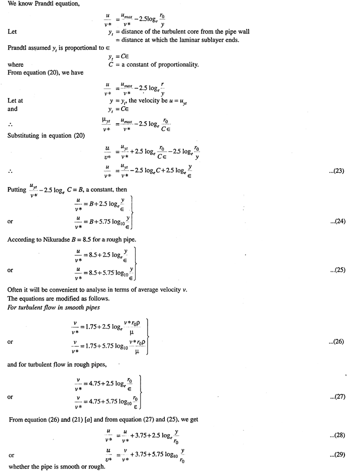


Where 

Similarly, for pipe 2


