UNIT 6
GVF in Open Channel Flow & Fluid flow around Submerged Objects
Q1. What are the Basic Assumptions of GVF ?
Ans- Basic Assumptions of GVF
Q2. Explain in detail - Dynamic equation of GVF.
Ans-
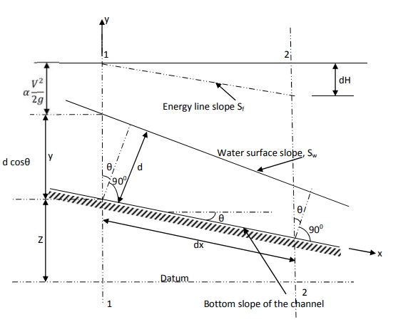
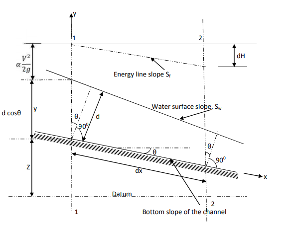
In the above figure, H = total energy (or head); E = specific energy; Z = vertical distance of the channel bottom above the datum in meters; d = depth of flow section normal to the bed in meters; θ = channel bottom slope angle; α = kinetic energy correction factor; V = mean velocity of flow through the section in m/s.
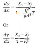
The dynamic equation for GVF for small bed slopes-
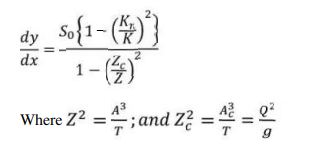
In terms of section factor the dynamic equation can be written as-
Z is the section factor at depth y and Zc is the corresponding section factor at critical
depth Yc. This equation is commonly used with direct integration technique.
In terms of Energy equation, the dynamic equation can be written as-
This is called the differential energy equation of gradually varied flow. This equation is very useful in developing numerical techniques for the gradually varied flow profile computation.
Q3. Explain the Classification of channel bed slopes and Various GVF profiles.
Ans- Classification of channel bed slopes
For a given channel with a known Q = Discharge, n = Manning coefficient, and S0 =Channel bed slope, yc = critical water depth and y0 = Uniform flow depth can be computed. There are three possible relations between y0 and yc as
1) y0 > yc ,
2) y0 < yc ,
3) y0 = yc .
For horizontal (S0 = 0), and adverse slope ( S0 < 0) channels,
Horizontal channel, S0 = 0→ Q = 0,
Adverse channel , S0 < 0 , Q cannot be computed,
For horizontal and adverse slope channels, uniform flow depth y0 does not exist.
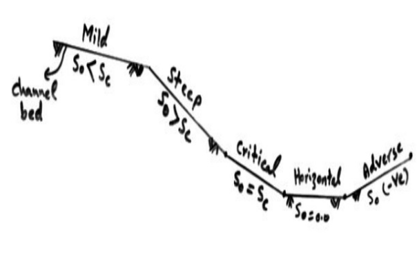
Based on the information given above, the channels are classified into five categories as Indicated in Table

Various GVF profiles
The surface curves of water are called flow profiles (or water surface profiles).
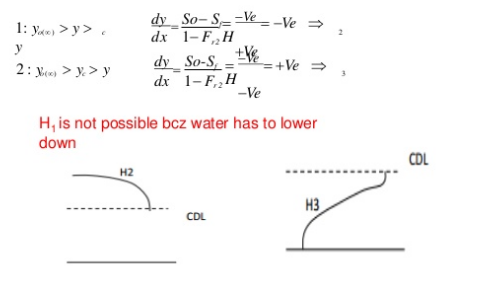
Depending upon the zone and the slope of the bed, the water profiles are classified into 13 types as follows:
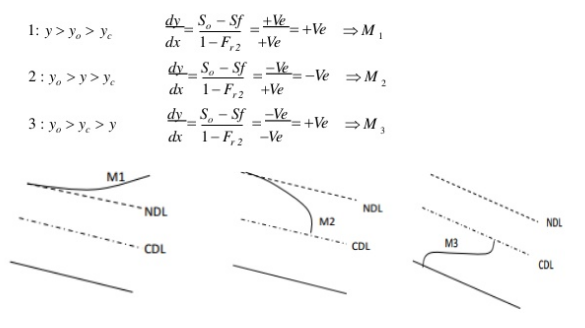
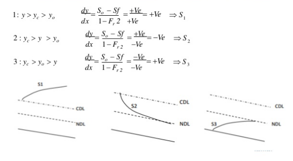
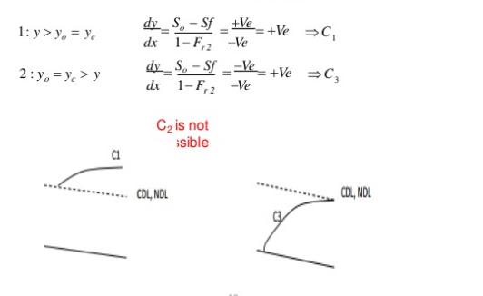
In all this curves, the letter indicates the slope type and the subscript indicates the zone. For Ex. S2 curve occurs in the zone 2 of the steep slope.
-Classification of Surface Profiles
1) Mild slope (M)
Y0 > Yc Type 1: If the stream surface lies above both
the normal and critical depth of flow
(M1,S1)
S0 < Sc
2)Critical slope (C)
Y0 = Yc Type 2: If the stream surface lies between
the normal and critical depth of flow
(M2,S2)
S0= Sc
3)Steep slope (S)
Y0 < Yc Type 3: If the stream surface lies below both
the normal and critical depth of flow
(M3,S3)
S0 > Sc
3)Horizontal slope (H)
S0= 0
4)Adverse slope (A)
S0= -ve

B. Steep Slope (S)
C. Critical Slope (C)
D. Horizontal Slope (H)
E. Adverse Slope (A)
Q4. Explain the Definition of drag and lift.
Ans-
- The component of total force FR in the direction of motion is called 'Drag' and is denoted by Fp. Drag, thus, is the force exerted by the fluid on the body in the direction of motion.
- Drag force resists the motion of the body or fluid Wind resistance to a moving car, water resistance to a moving torpedo are the examples of drag, Power is required to overcome drag anta hence drag is reduced to the possible minimum.
- The component of the total force in the direction perpendicular to the direction of motion is known as 'Lift and is denoted by FL. Thus, the lift is the force exerted by the fluid normal to the direction of motion. It can be seen that the lift force can exist only if the axis of the body is inclined to the direction of flow.
- Further, if the body is symmetrical and its axis is parallel to the direction of motion, the lift will be zero and only drag force will exist.
- The weight of an airplane moving in air is balanced by the lift force due to air on the airplane.
Q5. Explain the Expressions for drag and lift.
Ans- Expressions for drag
Pressure force equal to ‘p dA ‘normal to area dA
Shear force equal  dA along the tangent to dA
dFD = Drag force on the element
=Component of ‘ p dA' in the horizontal direction
+Component of  dA ‘in horizontal direction
=p. dA cos  +
+
 dA sin
FD= FD =
FD =  dA.cos
 +
+  dA. Sin


in case of a flat plate held parallel to the stream = 90", cos
 = 0, sin
  =1 and hence
FD = only friction drag


hence
FD = only pressure drag.
= -p.dA.sin +
+ . dA. cos
FL =  dA.sin
 +
+  dA. Cos
Drag force: FD =CD x A x
Lift force: FL =CL x A x
FR = +
+
Q6. Explain Coefficient of Drag and Coefficient of Lift.
Ans – Coefficient of drag:
=pdA cos  +
+  dA cos (90° -
 )
)
= pdA cos +
+ dA sin


= cos
cos  dA +
dA +  sin
sin  dA.
dA.


FD =CD x A x
CD=Coefficient of drag
Coefficient of lift :
=-pdA sin  +
+  dA sin (90° -
 )
)
=- pdA sin +
+ dA cos
FL = dA cos
  +
+  dA sin
  .
.
FL =CL x A x
FL=Coefficient of lift
Q7. Explain the Types of drag.
Ans- Types of drag:
1. Skin friction drag
2. Pressure drag
3. Profile drag
4. Deformation drag
5. Wave drag
6. Induced drag
2. Pressure Drag:
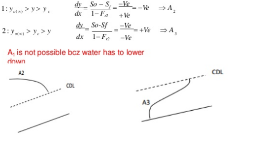
3. Profile Drag or Total Drag:
4. Deformation Drag:
5. Wave Drag :
6. Induced Drag :
Q8. Explain the Drag on a sphere and also Drag on a cylinder.
Ans – Drag on a sphere:
Let U = Velocity of the flow of fluid over the sphere,
D = Diameter of the sphere.
p = Mass density of the fluid, and
H = Viscosity of fluid.
FD =3
Thus, Skin friction drag, F =
= FD =
FD =
 3
3 = 2
= 2
Pressure drag, F =
= FD =
FD =
 3
3 =
= 
(i) Expression of Cd, for Sphere, when Reynolds Number is less than 0.2:
FD =CD x A x
FD =3


3 CD x
CD x 

= =
= 
The equation is called 'Stoke's law'.
(ii) Value of CD, for Sphere when Re, is between 0.2 and 5:
CD = 

 ]
]
is called Oseen formulae and is valid for R, between 0.2 and 5.
(iii) Value of CD for Re, from 5.0 to 1000:The drag co-efficient for the Reynolds number from to 1000 is equal to 0.4.
(iv) Value of CD for Re, from 1000 to 100,000: In this range, Cp is independent of the Reynolds number and its value is approximately equal to 0.5.
(v) Value of CD for Re, more than  : The value of C, in approximately equal to 0.2 for Reynolds number more than
  .
.
Drag on a cylinder:
Consider a real fluid flowing over a circular cylinder of diameter D and length L, when the cylinder is placed in the fluid such that its length is perpendicular to the direction of flow. If the Reynolds number of the flow is less than 0.2, the inertia force is negligibly small as compared to viscous force and hence the flow pattern about the cylinder will be symmetrical.
As the Reynolds number is increased, inertia forces increase and hence they must be taken into consideration for the analysis of flow over a cylinder. With the increase of the Reynolds number, the flow pattern becomes unsymmetrical with respect to an axis perpendicular to the direction of flow.
The drag force, i.e., the force exerted by the flowing fluid on the cylinder in the direction of flow depends upon the Reynolds number of the flow. From experiments, it has been observed that:
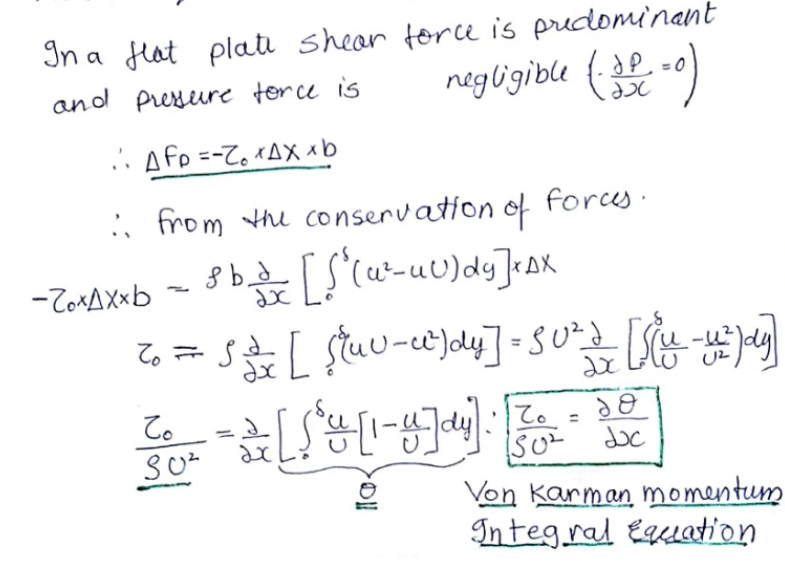
Q9. Explain Drag on a flat plate.
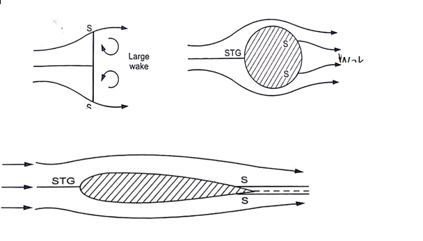
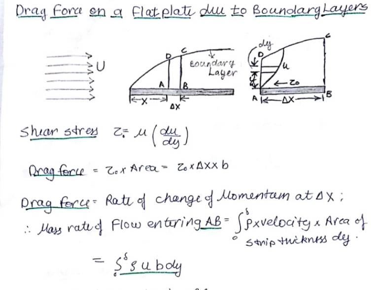
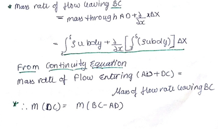
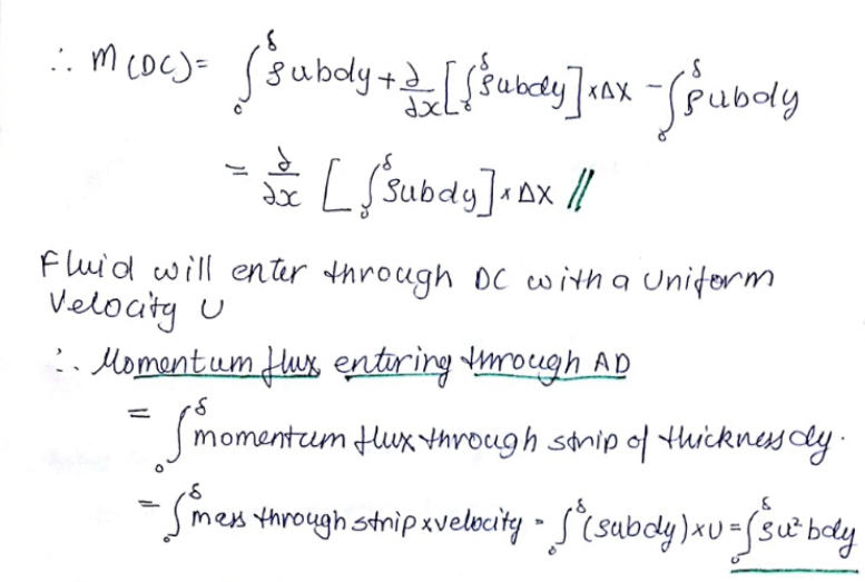
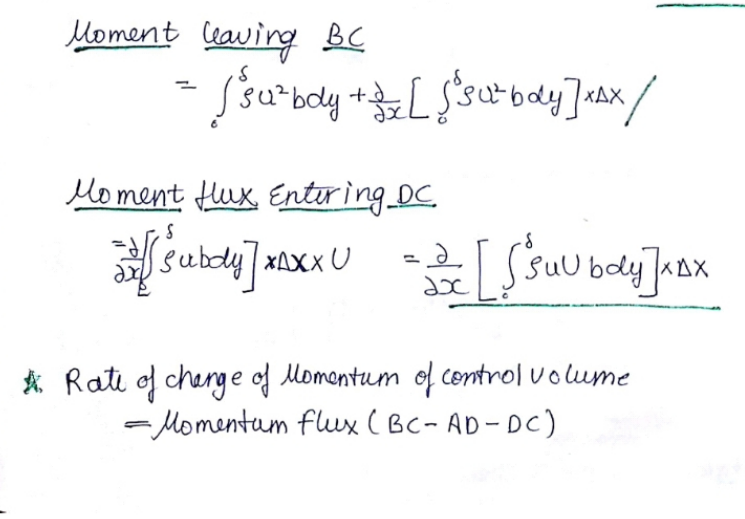
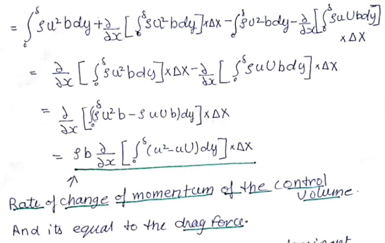
Ans- Drag on a flat plate:
Q10. Explain Karman‘s vortex street.
Ans- Karman‘s vortex street

(i)Symmetrical configuration which is not stable at all and
(ii) Staggered configuration.

Ut = = circulation around the vortex
f = 0.198  [1-
[1- ]
]
f  = 0.198 [1-
 ]
]

Q11. Explain Lift on cylinder.
Ans- Lift on a Circular Cylinder:
1. In the case of an ideal fluid passing past a circular cylinder, the flow pattern is symmetrical and hence there is no lift acting on the cylinder. The velocity at any point on the l or hE cylinder along the tangent to the cylinder is given by,
u = 2.U. sin 
2. If a constant circulation is imparted to the cylinder, the flow pattern around the cylinder will consist of streamlines in the form of concentric circles. In this case, the peripheral velocity is given by,
 =
=
3. The flow over a circular cylinder with constant circulation can be analyzed by the superimposition of the above two cases. The resultant flow pattern. The velocity at any point on the surface of the cylinder can be obtained by vectorial addition of the above two velocities as :
u = 2.U.sin +
+ 
4. For the upper half of the cylinder,  varies from 0° to 180° and sin e is positive and hence 2.U.sin e is positive. For the lower half, 2.U.sin
  is negative since sin e is – ve as
 varies from 180
 to 360°.
5. Thus the velocity around the upper half of the cylinder is higher than that on the lower half. Application of the Bernoulli's equation shows that the pressure on the lower half is higher than that in the upper half. As such there will be a force acting on the cylinder in the direction normal to the direction of flow.
This phenomenon of lift produced by rotating the cylinder (circulation) in a uniform flow of fluid is known as the "Magnus Effect'