Unit - 2
Shear Force and Bending Moment Diagram
Q1) Explain the concept of shear force in detail.
A1) Shear force:
The shear force at the cross section of a beam is defined as the algebraic sum of all the unbalanced vertical forces either left or right of the section.
SF = (∑ Fy)L = (∑ Fy) R
This is special to compression, which takes place while the two opposing forces are pushing into every different on the identical point (i.e. they may be not offset), ensuing in compressive stress.
When a structural member experiences failure through shear, components of it are driven in special directions, for example, while a piece of paper is reduce through scissors.
A shear force is a force implemented perpendicular to a surface, in competition to an offset force appearing within side the contrary direction
Sign convention for shear force:
An upward force to the left of section or downward force to the right of a section will be considered as a positive shear force.
When the force is downward to the left side of section and upward on the right of a section, will be considered as a negative shear force.
Q2) What do you mean by bending moment?
A2) Bending Moment:
The bending moment at any cross section of the beam is defined as the algebraic sum of moment of all the forces either left or right of the section.
BM= (∑MF)L = (∑MF)R
Bending moment is the response brought about in a structural detail whilst an outside pressure or second is carried out to the detail, inflicting the detail to bend
The inner response hundreds in a cross-segment of the structural detail may be resolved into a resultant pressure and a resultant couple. For equilibrium, the instant created via way of means of outside forces (and outside moments) should be balanced via way of means of the couple brought about via way of means of the inner hundreds. The resultant inner couple is known as the bending moment at the same time as the resultant inner pressure is known as the shear pressure.
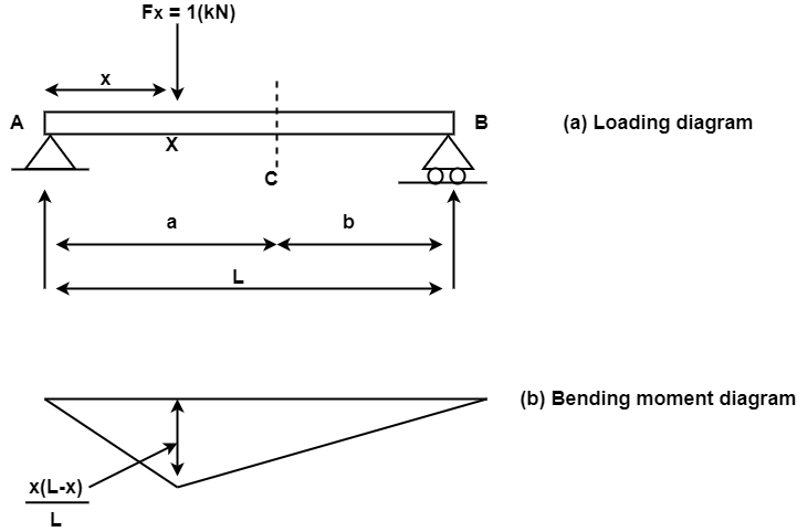
The bending moment at a segment C because of a unit load at X can further be received via way of means of direct equilibrium. The form of bending second diagram can be triangular with the peal cost going on under the unit load location. for this reason the bending second at any segment because of a un it load is most whilst the burden acts precisely on the segment below consideration.
If clockwise bending moments are taken as terrible (negative), then a terrible bending moment inside an detail will cause "hogging", and a superb ( positive) second will cause "sagging". It is consequently clean that a factor of 0 bending moment inside a beam is a factor of contra flexure—that is, the factor of transition from hogging to sagging or vice versa.
Sign convention of bending moment
Sagging bending moment: when clockwise moment on the left of the section or anticlockwise moment on the right of the section is considered as positive B.M. or sagging B.M.
Hogging bending moment: when the anticlockwise moment on the left of the section or clockwise moment on the right of the section is considered as negative or hogging B.M.
Q3) Explain the relation between shear force and bending moment?
A3) There is a relation amongst depth of load w, Shear Force F and Bending Moment M.
For the derivation of the relation amongst those three we recollect a definitely supported beam subjected to a uniformly allotted load w(x) for the duration of its period (L)
Re collect a small detail of period dx at a distance of x shape left aid.
Let the shear force and bending second at a segment positioned at a distance of x from the left aid be V and M, respectively, and at a segment x + dx be V + dV and M + dM, respectively.
The overall load acting within side the detail is W dx, acts on the middle of the detail period dx.
Considering the detail is in equilibrium take moments on proper facet of detail.
∑ Mx + dx = ∑ MR = 0
=- (M + dM) + M + V dx + wdx.dx/2 = 0
Neglecting small term wdx.dx/2=0
-dM+ V dx = 0
dM = V dx
dM/dx = V(x)
This relation implies that the primary by-product of the bending second with recognize to the gap is same to the shearing force. Rate of extrude of Bending Moment is same to Shear force.
dM/dx = F(x)
The equation also shows that the slope of the instant diagram at a specific factor is identical to the shear pressure at that identical factor. shows the subsequent expression:
∆M = ∫ V (x) dx
This states that the alternate in moment equals the region below the shear diagram.
Similarly, the vertical equilibrium within side the element,
∑ Fy = 0
V – w dx – (V+ dV) = 0
dV = -w dx
This relation implies that the primary by-product of the shearing pressure with admire to the space is same to the depth of the allotted load.
Rate of alternate of Shear Force is same to Intensity of loading.
dF/dx = - w(x)
The equation additionally shows that the slope of the shear pressure diagram at a selected factor is same to the depth of load at that equal factor
It additionally shows the following expression:
∆V = ∫ w (x) dx
This equation states that the alternate within side the shear pressure is same to the vicinity be neat the burden diagram.
By taking both relations
dV/dx = - w(x) and
dM/dx = V (x); we get one extra relation
d/dx = -w(x)
The relation implies that the second one by-product of the bending second with admire to the space is same to the depth of the allotted load.
Q4) What do you mean by concentrated load explain with neat sketch.
A4) Concentrated load:
This form of load acts exceedingly on a smaller area. For example, the pressure exerted via way of means of a chair or a desk leg at the helping ground or load exerted via way of means of a beam on a helping column are each taken into consideration to be focused load. In the derivation of the primary differential equation of equilibrium the loading depth turned into comfortably modeled as a non-stop variable.
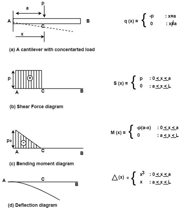
Q5) Explain what is uniform distributed load?
A5) Uniformly distributed load:
In a simply supported beam subjected to uniformly distributed load. The load intensity is a constant where by the shear force diagram will have a linear variation. Also note that the value of the shear force at the extremities will be equal to vertical reaction at A and B. The bending moment diagram will have a quadratic variation owing to the linear variation of the shear force diagram. It has maximum value at the mid span location where the shear force change its sign the slope of the beam will have a cubic variation and hence the deflection will have a forth order variation. Its magnitude is designated by its intensity (N/m or KN/m).
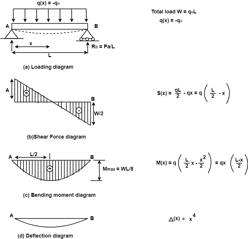
Q6) Explain uniform varying load in detail.
A6) Uniformly varying loads:
This type of load will be uniformly varying from zero intensity at one end to the designated intensity at the other end. A triangular block of brickwork practically imposes such a loading on a beam
The behavior of beam depends on which end (free end or fixed end) the load intensity is maximum. When load intensity is maximum at the free end the bending moment and deflection throughout the beam are bound to be larger compared to the case where the load intensity is maximum at the fixed end. The support reaction at A will be same in both the beams and shear force in the beam at a will also be identical for both. A shear force (SF) is defined as the algebraic sum of all the vertical forces, either to the left or to the right-hand side of the section.
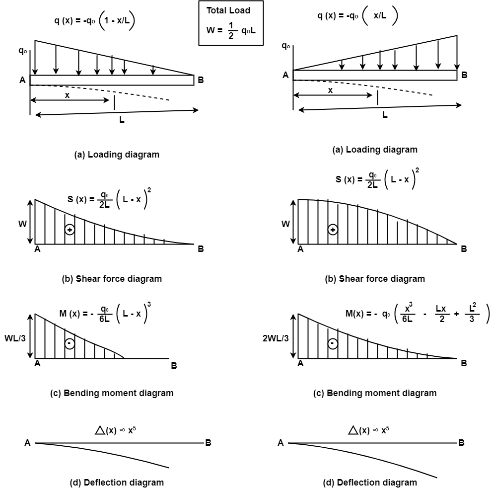
Q7) A simply supported beam of length 6 m carries point load of 3 KN and 6 KN at distances of 2 m and 4 m from the left end. Draw the shear force and bending moment diagrams for the beam
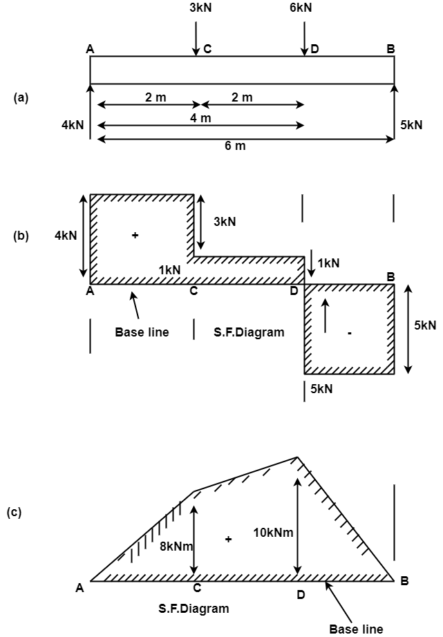
A7)
Find reaction RA and RB.
Upward load =Downward loads
RA+ RB = 9 KN
Taking moments of the force about A,
RBx6 = 3x2 + 6x4
30RB =5kN
RA= 4kN
Mechanics of Materials
18 M EI 33
Taking moments of the force about A,
RBx6 = 3x2 + 6x4
30RB=5kN
RA= 4kN
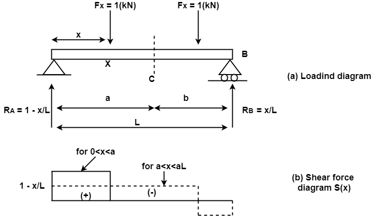
Shear Force
FA= + RA= + 4kN
Shear force between A and C is constant and equal to + 4 KN
Shear force at C,
Fc = + 4 -3.0 = + 1kN
Shear force between C and D is constant and equal to + 1 KN.
Shear force at D,
FD= + l -6 = -5kN
The shear force between D and B is constant and equal to -5 KN
Shear force at B,
FB= -5KN
The shear force diagram is drawn as shown in Fig.
Bending Moment Diagram
B.M.at A,
MA=0
B.M.at C,
Mc= RA x 2 = 4x2 = + 8KN/M
B.M.at D
MD= RA x 4 –3 x 2 = 4 x 4 –3 x 2 = + 10KN/M
B.M.at B,
MB=0
The bending moment diagram is drawn as shown in Fig.
Q8) Explain shear force diagram, point of contra flexure and important points of shear force and bending moment diagram.
A8) 1. Shear force diagram:
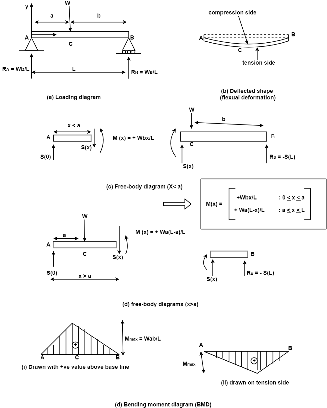
The shear force obtained analytically are representing by plotting shear force as ordinate (y- axis) against the position of cross section as abscissa ( x- axis) the diagram obtained is called as shear force diagram.
Point of contra flexure:
It is the point at which bending moment diagram change its sign generally bending moment at the point is equal to zero. It is definitely occurring in case of overhang beam within support. Point of contra flexure is calculated by equating expression of B.M.
BMXX = 0
Important point of shear force diagram and bending moment diagram:
1) Base of S.F.D. and B.M.D is equal to to length of the beam.
2) Positive value of S.F and B.M are plotted above the base line and negative below the base line.
3) It there is no loading between any two sections the magnitude of S.F. will not change between the given section and S.F.D will be horizontal.
4) If there vertical load or reaction at any section the S.F. the section will suddenly increase or decreases depending on the direction of vertical load.
5) If there is u.d.l. between two sections the shear force diagram is inclined line.
6) If there is u.v.l. between two sections the S.F. diagram is parabolic curve.
7) Variation of B.M.D is parabolic for udl.
8) Variation of B.M.D. is cubic for uvl.
Q9) Explain bending moment diagram in detail.
A9) Bending moment diagram:
The bending moment obtained analytically are represent by plotting bending moment as ordinate (y- axis) against the position of cross section as abscissa ( x- axis) the diagram obtained is called bending moment diagram.
The bending moments are sagging throughout the beam and hence according to our usual sign convention they have positive value.


Q10) A simply supported beam 7m long is carrying three point load 100N, 600N, and 175N acting at 2m, 4m, and 5.5m from left support. Determine support reaction and draw S.F. and B.M.

A10)
1. Support reaction:
Let RA and RB be the support reaction A and E
∑MA = 0
-RE X 7+ 100 X 2 + 600 X 4 + 175 X 155 = 0
RE = 508.93N
 + ∑ Fy = 0
RA -100-600-175+RE = 0
RA = 366.07N
2. Shear force calculation:
Shear force just left of A SFAL = 0
Shear force just right of A SFAR = 366.07N
Shear force just left of B SFBL = 366.07N
Shear force at just right of B SFBR = 366.07-100 = 266.07N
Shear force just left of C SFCL = 266.07N
Shear force just right of C SFCR = -333.93N
Shear force just left of D SFDL = -333.93N
Shear force just right of D SFDR = -508.93N
Shear force just left of E SFEL = -508.93N
Shear force just right of E SFER = 0

3. Bending moment calculation
Consider bending moment on the left side of section
Bending moment at point A BMA = 0
Bending moment at point B BMB = 366.07X2 = 732.14KN.M
Bending moment at point C BMC = 366.07X 4 -100X2 = 1264.28 KN.M
Bending moment at point D BMD = 366.07X 5.5 -100X3.5-600X1.5 = 763.38KN.M
Bending moment at point E BME = 0

Q11) A simply supported beam of span L is carrying uniformly distributed load w over its entire span calculate S.F. and B.M. also draw SFD and BMD.
A11)

1. Support reaction:
Since the beam is subjected to the symmetrical loading support reactions is half of the total load
 RA = RB = W x L
2
2. Shear force calculation:
Consider a section x-x at the distance X from A
∑ (SF)XX = WL/2 –WX
At x = 0, SFA = WL/2
At x= L, SFB = WL/2- WL = -WL/2
3. Bending moment:
Consider a section x-x at the distance x- from left support
∑ (BM)XX = WL/2. X- (W.X) X/2 = WL/2 = WX2/2
Bending moment equation shows that BM curve is parabolic
At x=0 BMA = 0
At X= L BMB = WL/2 X L – WL2/2 = 0
Position and magnitude of maximum BM
Maximum bending moment occurs where shear force is zero.
Now location of point where SF = 0
∑ (SF) XX = 0
WL/2 – WX = 0
Therefore x= L/2
Bending moment at x = L/2
BM = WL/2 (L/2) – W/2 (L/2)2 = WL/4-WL2/8
 BM = WL2
8