Unit - 6
Slope and Deflection of Beams and Trusses
Q1) Explain slope and deflection method of determinate beam by Macaulay’s Method.
A1) Slope and Deflection of determinate beam by Macaulay’s Method
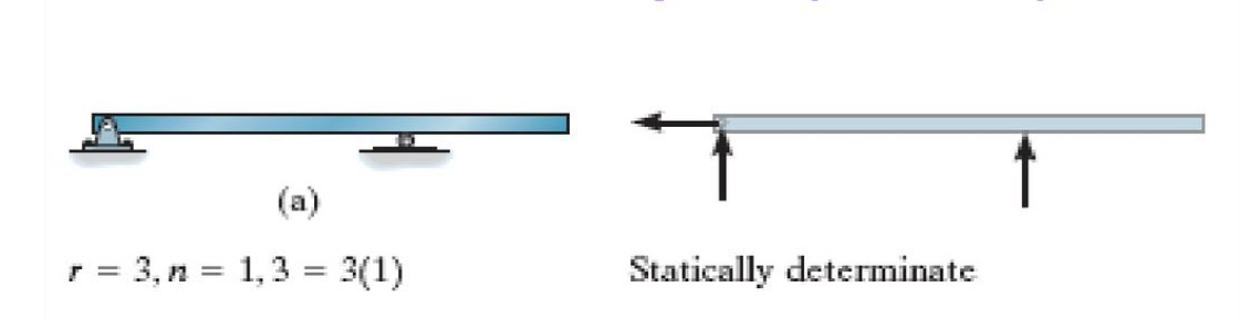
1. Determinate Beam: the determinate beam is that the beam in which unknown support reactions can be calculated by using static equilibrium equations only.
Example: simply supported beams, cantilever beams, single and double overhanging beams.
2. Slope and Deflection of beams
Macaulay’s method
(Double ∫∫ method)
(Integration)
3. Basics:
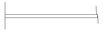
1. Elastic curve: Deformed shape of beam is called as elastic curve.
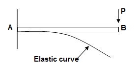
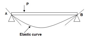
2. Slope: Angle made by tangent joint to the elastic curve with x-axis is called as slope.
3. Deflection: Translation of cross-section normal to the longitudinal axes of member is called as deflection.
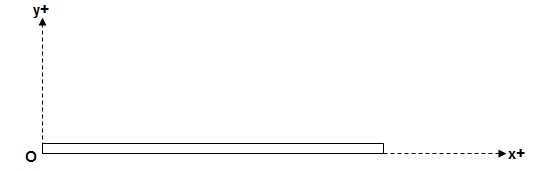
4. Reference System:
Left end of beam is taken as origin and reference system is as below.
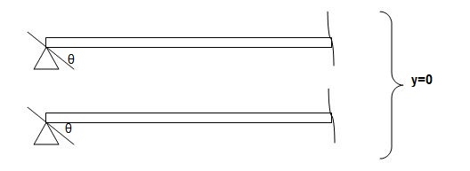
5. Sign conventions:
(A). Slope
ϴ + dy/dx = Anticlockwise rotation of tangent
dy/dx = clockwise rotation of tangent
(B) Deflection
+y = upward Deflection
-y = downward Deflection
6. Flexural Rigidity = (EI)
Product of young modulus of elasticity and moment of inertia of cross-section is called as Flexural rigidity (FI).
Unit: KN.m2
Note: Slope and deflections are inversely proportional to FI.
7. Boundary conditions:
These are nothing but support conditions.
i) At fixed end:
dy/dx = 0
y = 0
ii) At hinged and roller end
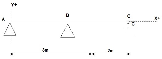
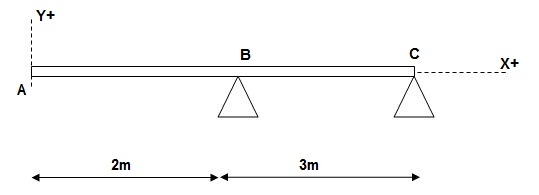
Q2) Write boundary conditions for following beams
A2)
1) 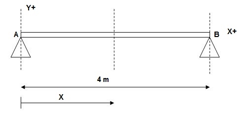
At x = 0; yA = 0
x = 4m; yB = 0
2)
At x = 0; yA = 0
x = 3m; yB = 0
3)
At x = 2m; yB = 0
At x = 5m; yC = 0
At x = 0; {dy/dx}A = 0
X = 0; yA = 0
Q3) Explain bm equation and concept of Macaulays Method.
A3) Concept of Macaulay’s Method
We have,
M/I = 6/y = E/R
Where; R = Radius of curvature
= {1 + (dy/dx)2 }3/2 / d2y/dx2
For beams values of dy/dx are very small
R ≈ 1/d2y/dx2
M/I = E/R, E/1/d2y/dx2 = Ed2y/1 x dx2
M/I = Ex (d2y/dx2)
M = EI.d2y/dx2 = - - - - F(x) = BM eqn
ϴ = EI (dy/dx) = ----------- +c1 = slope eqn
Deflection EI(y) = --------- + C1(x) + C2 = Defneqn
‘’ (Eqn of elastic curve)
B.M equations:
Note:
For writing BM equation always consider section at a distance x from origin, placed in right extreme zone.
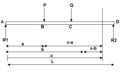
EI (d2y/dx2) = BMx = R1(x) | - P(x-a) | - Q(x-b)
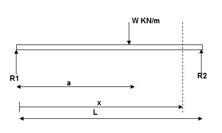
EI (d2y/dx2) = BMx = R1x | - w(x-a)2/2
EI (d2y/dx2) = BMx = R1(x) | - wx2/2 | + w(x-a)2/2
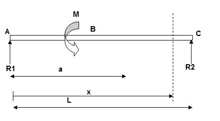
EI(d2y/dx2) = BMx = R1(x) | - M(x-a)
Q4) E = 200 GPa = 200 x 103MPa / N/mm2 = 200 KN/mm2
I = 3 x 108 mm4
EI = 200 x 3 x 108 KNmm2
EI = 600 x 102 KNm2
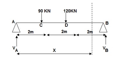
A4) Reactions,
∑MA = VB(6) – 90 x 2 – 120(4) = 0
VB = 660/6
VB = 110 KN
∑Fy = VA + VB – 90 – 120 = 0
VA = -110 +90+120
VA = 100 KN
∑Fx = HA = 0
EI (d2y/dx2) = 100(x) | - 90(x-2) | -120(x-4) ---(1)
EI (dy/dx) = C1 + 100x2/2 | - 90(x-2)2/2 | -120(x-4)2/2 ---(2)
EI(y) = C1(x) + C2 + 100x3/6 | - 90(x-2)3/6 | -120(x-4)3/6 ---(3)
Boundary conditions:
At x=0 | yA = 0, put in (3)
C2 = 0
At x = 6m, yB = 0, put in (3)
6C1 + 100 x 36 – 90 x (4)3/6 – 120 x 23/6 = 0
6C1 + 3600 – 960 – 160 = 0
6C1 = -2480
C1 = (-) 413.33
Slope &Deflection:
X = 0, in (2),
(dy/dx)A = (-) 413.33/EI = (-)4133.33/600 x 102
 = 6.88 x 10⁻³ rad( )
X = 6m in (2),
EI(dy/dx)B = (-)413.33 + 100(6)2/2 – 90(4)2/2 – 120 x (2)2/2
= - 413.33 + 1800 – 720 – 240 = 426.67
 (dy/dx)B = 7.11 x 10⁻³rad( )
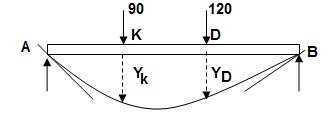
X = 2m in (3),
Yc = -413.33 x 2 + 100 x 23/6
= - 826.66 + 133.33
= -693.22/EI = -693.32/600 x 102 = -11.55
 Yc = -11.55 mm( )
X = 4m in (3)
yD = -413.33 x 4 + 100 x 43/6 – 90 x 23/6
= -706.6/EI = -706.6/600 x 102
= - 11.77 mm
 yD = 11.77 mm( )
For maximum deflection
Let X > 2m
< 4m - zone CD
EI(dy/dx)CD = - 413.33 + 100/2x2 – 90(x-2)2/2 = 0
-413.33 + 50 x2 – 45(x-2)2 = 0
-413.33 + 50x2 – 45(x2-4x+4) = 0
-413.33 + 5x2 + 180x – 180 = 0
5x2 + 180x – 593.33 = 0
X = 3.03 >2m
<4m
Assumption is correct.
X = 3.03m in (3)
Ymax = -413.33 x 3.03 + 100(3.03)3/6 – 90 x (3.03-2)3/6
= -1252.38 + 463.63 – 16.39
= - 805.14/EI
Q5) EI = 4 x 10⁴ Kn.m2
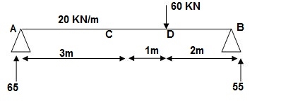
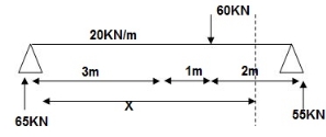
A5) Reactions:
∑MA = 0
VB x 6 – 20 x 3 x x 1.5 – 60 x 4 = 0
VB = 55KN
∑Fy = 0
VA + VB – 60 – 20 x 3 = 0
VA = 65 KN
EI (d2y/dx2) = 65 x x | - 20 x x2/2 | + 20 x (x-3)2/2 | - 60(x - -(1)
EI {dy/dx} = C1 + 65x2/2 | - 20 x x3/6 | + 20(x - 3)3/6 | - 60(x - 4)2/2 - - (2)
EI(y) = C1(x) + C2 + 65x3/6 | - 20 x x4/24 | + 20(x-3)4/24 | -60(x-4)3/6 --(3)
Boundary conditions:
At x=0, yA = 0, put in (3)
C2 = 0
X = 6m, yB = 0 put in 3
C1 x 6 + 65 x 62 – 20 x 63/4 + 20 x 34/24 – 60 x 23/6 = 0
C1 = -207.91
Slope &deflection:
X = 3m in (2)
(dy/dx)c = -207.91 + 65 x 32/2 – 20 x 33/6 = -5.41/EI
= -1.35 x 10⁻⁴
 (dy/dx)c = 1.35 x 10⁻⁴ rad( )
X = 3m in 3
yC = -207.9 x (3) + 65 x (3)3/6 – 20 x 34/24 – 398/EI
= - 9.967 x 10-3
= -9.967mm
 yC = 9.967 mm( )
x = 4m in (3)
yD = -207.9 x 4 + 65 x 43/6 – 20 x 43/24 + 20/24
= - 350.7/EI
 = 8.76 mm ( )
Q6) EI = 32.5 x 10³ Kn.m2
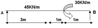
A6) Reactions:
∑MA = 0
VB (5) – 45 x 3 x 1.5 + 30 = 0
VB = 34.5 KN
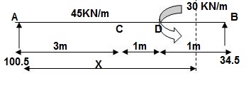
EI {d2y/dx2} = 100.5 x x – 45x2/2 | + 45 x (x-3)2/2 | -30(x-4)0 -- (1)
EI {dy/dx} = C1 + 100.5x2/2 – 45x3/6 | + 45 x (x-3)3/6 | - 30(x-4) --(2)
EI(y) = C1(x) + C2 + 100.5x3/6 – 45x4/24 | + 45 x (x-3)4/24 | - 3(x-4)2/2 --(3)
Boundary conditions:
At x=0; yA = 0 put in eqn3
C2 = 0
At x=5; yB = 0
5C1 + 100.5 x 53/6 – 45(5)4/24 + 45(2)4/24 – 30/2 = 0
C1 = (-) 187.375
Slope &Deflection:
X=3m in (2)
(dy/dx)c = -187.375 + 100.5 x 32/2 – 45(3)3/6
= 62.375/32.5 x 103
 (dy/dx)c = 1.919 rad( )
X = 3m in (3)
yC = -187.375 x 3 + 100.5 x 33/6 – 45 x 34/24
= - 261.75/32.5 x 103
= - 8.053mm
 yC = 8.053mm( )
x = 4m in (3)
yD = -187.375 x 4 + 100.5 x (4)3/6 – 45 x (4)4/24 + 45/24
= - 155.625/32.5 x 103
= - 4.78 mm
 yD = 4.78 mm( )
Q7) E = 200 GPa
I = 6.2 x 107mm4
EI = 200 x 6.2 x 107 KN.mm2
= 200 x 6.2 x 107 x 10-6 KNm2
EI = 12400 KNm2
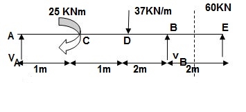
A7) Reactions:
∑MA = 0
VB x 4 – 25 – 37(2)(3) – 60(6) = 0
VB = 151.75 KN
VA + VB – 60 – 37 x 2 = 0
VA = (-)217.75 KN
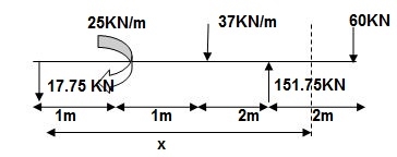
EI {d2y/dx2} = -17.75 x | + 25(x-1)0 | - 37 x (x-2)2/2 | + 151.75(x-4)2/2 | + 37 x (x-4)2/2 --(1)
EI {dy/dx} = C1 – 17.75x2/2 | + 25(x-1)| - 37(x-2)3/6 | + 151.75(x-4)2/2 | + 37(x-4)3/6 --- (2)
EI(y) = C1x + C2 – 17.75 x3/6 | +25(x-1)2/2 | -37(x-2)4/24 | + 151.75(x-4)3 | + 37(x-4)4/24 ---(3)
Boundary condition:
At x=0; yA=0 C2 = 0 (in eqn (3))
At x=4;yB=0 put in eqn(3)
4C1 – 17.75 x 43/6 + 25 x 32/2 – 37 x 23/6 = 0
C1 = 25.4
Slope and deflection:
X = 2m in (2) & (3)
(dy/dx)D = 25.4 –17.75 x 2 + 25
= 14.9/EI
 (dy/dx)D = 1.201 x 10⁻³rad( )
yD = 25.4 x 2 – 17.75 x 23/2 + 25/2
= 39.63/12400
 yD = 3.196 mm( )
x = 6m in (2) & (3),
(dy/dx)E = 25.4 – 17.75 x 62/2 + 25 x 5 – 37(4)3/6 + 151.75(2)2/2 + 37 x 23/6
= -210.183/12400
 = 0.017 rad( )
YE = - 341.7/12400 = 27.5mm
Q8) Find strain energy?
A8) ∑MA = 0
30 x 2 – RB x 4 = 0
RB = 15
VA = VB = 15 KN
BMC = BMD = 15(1) = 15 KN.M
BMC = 15(2) = 30 KN.M
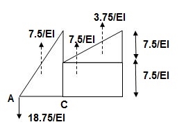
‘M/EI’ Dia.
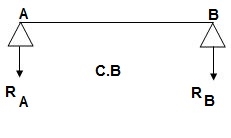
C.B
A1 = 1 / 2 x 1 x 15/EI = 7.5/EI
A2 = 2 x 7.5/EI = 15/EI
A3 = 1 /2 x 2 x 7.5/EI = 7.5/EI
A4 = 1 / 2 x 15/EI x 1 = 7.5/EI
Analysis of conjugate beam
∑MA = -RB (4) + 1/EI {7.5(2/3 x 1) + 15(2) + 7.5(2) + 7.5(3 + 1/31)} = 0
= - RB x 4 + 1/EI [5 + 30 + 15 + 25 ] = 0
RB x 4 = 75/17250
RB = 18.75/EI
∑fy = 0
-RA + RB + A1 + A2 + A3 + A4 = 0
RA = 18.75/EI
RA = RB = ½{A1 + A2 + A3 + A4} = 18.75/EI
Slope & Deflection
(ϴA)R.B = (SFA)C.B = (-)18.75/EI

 = 18.75/EI xC = 1.086 x 10⁻³rad xC

 (ϴB)R.B = (SFB)C.B = 18.75/EI xC = 1.086 x 10⁻³ rad xC
(ΔE)R.B = (BME)CB
(BME)CB= 1/EI { -18.75 + 7.5(1 + 1/3 x 1) + 7.5(0.5) + 3.75 (1/3 x 1)}
=1/EI{-22.5}

 ΔE = 22.5/EI xC = 1.304 mm xC
Q9) Find ϴC&ΔC= ?
Real Beam:
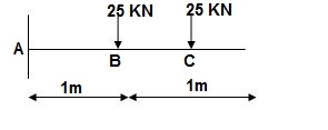
A9) BMD:
BMA = -25(1) – 25(2) = -75KNm
BMB = -25(1) = -25KNm
BMC = 0
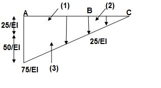
A1 = 25/EI x 1 = 25/EI
A2 = 1/2 x 1 x 25/EI = 12.5/EI
A3 = 1 / 2 x 50/EI x 1 = 25/EI
Conjugate beam:
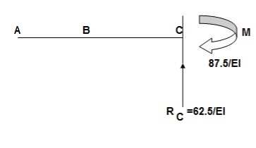
When force downward reaction is upward & when moment is clockwise in conjugate beam the moment is anticlockwise.
∑Fy = RC – 1/EI{25 + 12.5 + 125} = 0
RC = 62.5/EI
∑MC = - MC + 1/EI{25(1.5) + 12.5(2/3) + 25(1 + 2/3)} = 0
MC = 87.5/EI
Slope & Deflection
ϴC at Real Beam
(ϴC)RB = (SFC)C.B
=(-)62.5/EI
 ϴC = 62.5/EI ( )
(ΔC)RB = (BMC) CB
ΔC = (-) 87.5/EI
 ΔC = 87.5/EI ( )
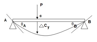
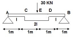
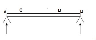
Q10) Find: ϴA, ϴBand Δ centre= ?
Real Beam:
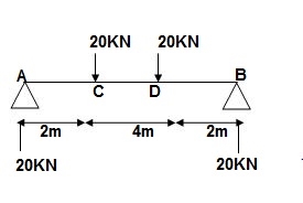
A10) BMD: VA = VB = 20 KN
BMA = BMB = 0
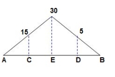
BMC = BMD = 20 x 2 = 40 KNm
A1 = 40/EI = A3
A2 = 160/EI
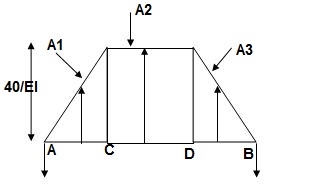
Conjugate beam:
Reactions of CB:
RA = RB = ½(A1 + A2 + A3)
= 1/2EI (40 + 160 + 40 )
= 240/2EI
= 120/EI
Slope &Deflection:
(ϴA)RB = (SFA)CB = (-)120/EI
 ϴA = 120/EI ( )
(ϴB)RB = (SFB)CB = (+)120/EI
 ϴB = 120/EI ( )
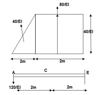
Shear force is zero -> Maximum BM(C.B)
BME = 40/EI x (2 + 1/3) + 80/EI(1) – 120(4)
= (-) 293.3/EI
 ΔE = 293.3/EI ( )
Q11) Propped cantilever and fixed beams by strain energy method
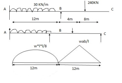
A11)


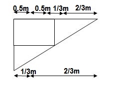
 A1 = 2 x wl2 x 12 = 2 x 30 x 122 x 12 = 4320 mm2
3 3 8


 x1 = l1 = 12 = 6 = 6m
2 2
A2 = 1 x wab x 12 = 1 x 240 x 4 x 8 x 12 = 3840 mm2


 2 2 12


 x1 = l2 = 12 = 6m x1 = L + a x2 = l +b


 2 2 3 3
Q12) Explain the procedure of displacement by Castiglione’s theorem.
A12) It states that displacement at a point of application of load in the direction of load is equal to partial derivative of strain energy of structure with respect to load.
1]. ӘU/ӘQi = Δj
U = strain energy
Qj = Force in the direction j
Δj = Displacement in the direction j
2]. Strain energy: Uaxial force = ∫L0P2dx/2EA
UB.M = ∫L0M2dx/2EI
U Torsion = ∫L0T2dx/2GJ
Deflection = translation
3]. Procedure of displacement analysis by Castiglione’s theorem:
Step 1:
Apply imaginary load ‘Q’ at section where displacement is required.
Note:
1]. For horizontal translation apply
‘Q’ in horizontal direction
For vertical translation apply force Q in vertical direction
2]. For finding ‘slope’ (rotation) apply couple Q.
Step 2:
Find support reactions and draw member F.B.D’s
Step 3:
Prepare table:
Zone origin limits EI M ӘM/ӘQ
Step 4:
Find displacement using Δj = ∫L0M/EI{ӘM/ӘQj} dx
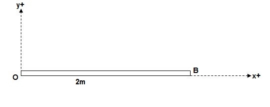
Find ΔB :
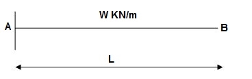
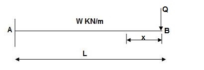
Zone Origin Limits EI M ӘM/ӘQ
BA B 0 to L EI –Q(x) – W(x2/2) -x
ΔB = ∫L0 M/EI(ӘM/ӘQ)dx = ∫L0{-W(x2/2)}(-x)dx
= W/2EI{x4/4}L0
 ΔB = WL4/8EI ( )
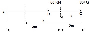
Q13) Find Vertical deflection at ‘c’,
EI = constant
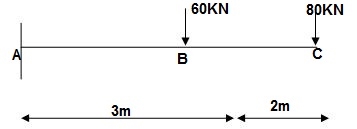
A13) M Diagram
From above Fig:
Table
Zone Origin limits EI M ӘM/ӘQj
CB C 0-2 EI -(80 + Q)x - x
BA C 2-5 EI -(80 + Q)x - x-60(x-2)
ΔC = ∫20-(80)x/EI {-x}dx + ∫52{80x – 60(x-2) (-x)dx/EI}
= ∫2080x2/EIdx + ∫52{80x2 – 60x2 + 2x}dx/EI
= 1/EI {213.33 + 4200}
 ΔC = 4413.33/EI ( )
Q14) Find deflection at ‘C’
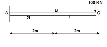
A14)
M Diagram
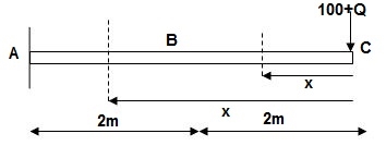
Zone Origin Limit EI M ӘM/ӘQ
CB C 0 – 2 EI - (100 + Q)x -x
BA C 2 – 4 EI -(100 + Q)x -x
ΔC = ∫20 – 100x/EI(-x)dx + ∫42 -100x/EI(-x)dx
= ∫20100x2/EIdx + ∫42100x2/2EIdx
= 266.66 + 1866.6/2
= 266.66 + 933.33
For cantilever always write load from free end. For simply write load from supports.
ΔC = 1200/EI
Q15) Find slope at ‘A’, deflection at ‘C’.
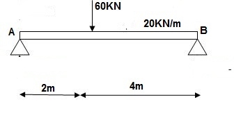
A15)
M Diagram
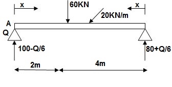
Reaction M dia.
∑MA = VB 6) – 20 x 6 x 3 – 60(2) – Q = 0
VB = 80 + Q/6
∑Fy = VA + VB – 60 – 20 x 6 = 0
VA = 100 – Q/6
Zone Origin limits EI M ӘM/ӘQ
AC A 0 – 2 EI (100-Q/6)(x) 1 – x/6+ Q – 20(x2/2)
BC B 0 – 4 EI (80+Q/6)(x)-20x2/2 x/6
ϴA = ∫20{100(x) – 10x2}{1-x/6} dx/dEI + ∫40{80x – 10x2}x/6dx/EI
= 1/EI{135.55 + 177.78}
 ϴA = 313.32/EI( )
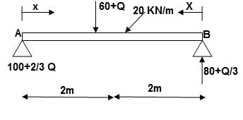
∑MA = VB (6) – 20(6)(3) – (60 + Q)2 = 0
VB = 80 + Q/3
∑Fy = VA + VB – (60 + Q) – 20(6) = 0
VA = -80 – Q/3 + 60 + Q + 120 = 0
VA = 100 + 2/3Q
Q16) Find deflection at ‘C’
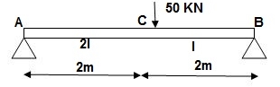
A16)
i) M Diagram
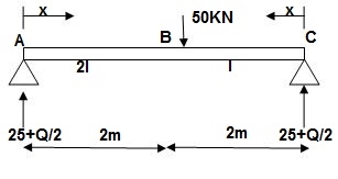
Zone Origin Limit EI M ӘM/ӘQ
AC A 0 – 2 EI (25 + Q/2)x x/2
BC B 0 – 2 EI (25 + Q/2)x x/2
ΔC = ∫20(25x)x/2dx/EI + ∫2025x(x/2)dx/2EI
= 33.33 + 16.66/EI
 ΔC = 50/EI( )
Q17) Find deflection at D
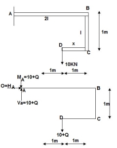
A17)
∑MA = MA – (10+Q)(1) = 0
MA = 10 + Q
∑Fy = VA – (10 + Q) = 0 VA = 10 + Q
∑Fx = HA = 0
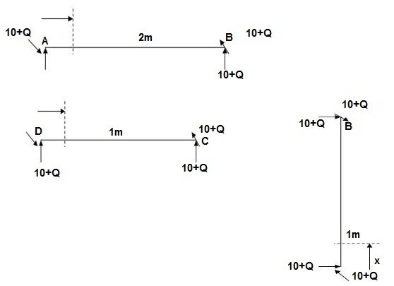
Zone origin limits EI M ӘM/ӘQ
AB A 0 – 2 2EI (10+Q)x-(10+Q) x-1
CB C 0 – 1 EI -(10 + Q) -1
DC D 0 – 1 EI -(10 + Q)x - x
ΔDy = ∫2 0(10x - 10) (x-1)dx/2EI + ∫10 -10(-1)dx/EI + ∫10 -10x(-x)dx/EI
= 3.33 + 10 + 3.33/EI
 ΔDy = 16.66/EI ( )


