Unit - 2
Analysis of redundant pin jointed frames and multi-storied multi-bay 2-D rigid jointed frames
Q1) Explain the analysis of redundant trusses by unit load method for external loading?
A1) Consider the truss which has hinged supports at both ends.
External indeterminacy Number of unknown reaction (R) -equilibrium equation (E) 04-03= 01 Internal indeterminacy=m-2j+3-9-2x6+3=0
Degree of static indeterminacy = 01
Assuming vertical component at D as a redundant force
Then, restraint in that direction is to be removed and vertical force R, is treated as an additional unknown force acting on that structure. The condition for consistency is that turns of should have zero vertical displacement to represent the given truss.
As the truss is a determinate truss, its displacement can be evaluated and the consistency condition can be imposed on it.
For finding the displacements, unit load method may be used because this method is ideally suited for finding the displacement in trusses.
Now, the total displacement in the truss may be split into two parts:
One due to the given loadings (i.e., P- Analysis) and the ether due to the redundant force Rp Let the forces developed in the members of the truss, due to given loadings be P Analysis and that due to unit load at D in the direction of Ro be K.
Then According to unit load method, the vertical displacement of B due to the given loading is given by
Vertical displacement due to RD

The displacement of B

But according to consistency condition the vertical displacement is equal to zero


Q2) Write down the procedure of analysis the indeterminate truss of one degree redundancy?
A2) Procedure to analyze the indeterminate truss of one degree redundancy
Step 1) Find degree of indeterminacy
Step 2) Select the redundant member
Step 3) Remove the redundant member and find the force P is members of the truss for the given load system
Step 4) Remove the load given system
Step 5) Find  and
and  for each member
Step 6) Find redundant force
Step 7) Find the force in any member by the reaction
Q3) Analyze the frame shown in fig. for the force in various members. All the members may be assumed to have the same (l/AE)
A3) Step 1) Degree of redundancy
R-E= 3-3 = 0
Degree of internal redundancy= m-(2j-3) = 6-(2x4-3) =1
Total degree of redundancy= 0+1 = 1
Step 2) Let AD be the redundant
Remove member AD
Step 3) P forces


b. Consider joint C in equilibrium


c. Consider joint D in equilibrium


K forces
Remove external load
Apply pair unit load


B. Consider joint C in equilibrium


Find 
Member | P | K | PK | K^2 | Final forces (F) =P+KR | Remark |
AB | 0 | +0.71 | 0 | 0.504 | -0.62 |
+ Tension -Compression |
AC | 0 | +0.71 | 0 | 0.504 | -0.62 | |
AD | 0 | -1 | 0 | 1 | 0.88 | |
BD | 5 | +0.71 | +3.55 | 0.504 | 4.37 | |
BC | 0 | -1 | 0 | 1 | 0.88 | |
CD | 0 | -0.71 | 0 | 0.504 | -0.62 |


Step 6) Find redundant force R

Step 7) Final forces
Final force in all member is given by F= P+KR
Final force is shown in table
Q4) What do you mean by lack of fit?
A4) Lack of fit is defined as little longer or little shorter length of any member in truss.
If any one member of a redundant frame had lack of fit stress will be induced an all members of the redundant frame when that member is forced in position. The redundant member (R) due to lack of fit can be determine by using the following formula

Where
λ= Shorting or excess of member in mm
+ ve = if member is short in length
-Ve if members excess in length
Final force in various are determined by the formula F= P+KR
Q5) Find the force of all member of the frame shown in fig. If the member BC short in length by 10 mm and is force into position Take E= 2x10^5 N/mm2 All member have same area of cross section of 10 mm2
A5)
Dsi = R-E= 0
2. P force
m- (2j-3) = 1
There is no external force acting on truss
p force due to external loading in various member will be zero

3. K force
Remove member BC
Apply unit load at joint c
Find the K force
Member | L | P | K(KN) | K^2 L | Final force F= P+KR | Remark |
AB | 4000 | 0 | -0.80 | 2560 | 9.26 |
+= Tension - = Compression |
AC | 3000 | 0 | -0.60 | 1080 | -6.94 | |
AD | 5000 | 0 | +1.00 | 5000 | +11.57 | |
BD | 3000 | 0 | -0.60 | 1080 | -6.74 | |
BC | 5000 | 0 | +1.00 | 5000 | +11.57 | |
CD | 4000 | 0 | -0.80 | 2560 | -9.26 |
|
|
|
| ∑ | 17280 |
|
Step 4) Redundant force R

Where, 
E= 2x 10 5 N/mm2
A= 100 KN/mm2
Q6) Explain the concept dinking of support and temperature changes (indeterminacy up to second degree)?
A6) 1. Sinking of support:
Dsi = 1 (Internal)
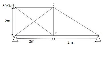
DSi = (m+r) – 2 J
= (8 +3) – 2 (5)
= 11 – 10
DSi = 1 (total)
(DSi) external = R – 3 = 0
(DSi) internal = 1
2) Selection of ‘Q’
Let Q = FBE (Tensile)
3) P – Dia & K-Dia
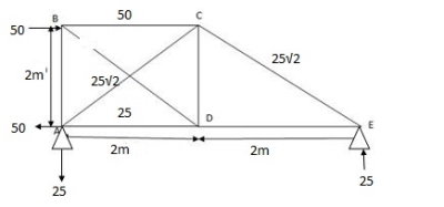
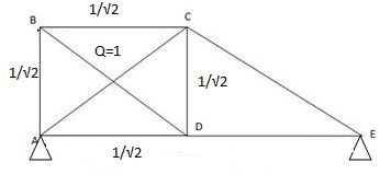
 15 diagonals in tension then all sides are in compression + DA = - 1 2
Sin 270 = 1 sin45
= -1 x -1
= 1
P-analysis
∑MA=0
-50 x 2 + VC x 4 = 0
VC = 25KN
∑FY=0
HA .VA + VC = 0
VA = - 25 KN
∑FX=0
HA = - 50KN
K-analysis:
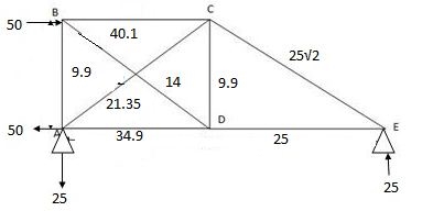
Sr. No. | Member | L (mm) | P (KN) | K | PKL (x103) | K2L (x103) | Q | F=P + KQ |
1. | AB | 2000 | 25 |
| -35.35 | 1 |
| 34.9 |
2. | BC | 2000 | 25 | 0 | 0 | 0 |
| 25 |
3. | CD |
|
| 0 | 0 | 0 |
| -25 |
4. | DE | 2000 | -50 |
| 70.71 | 1 | -14 | -40 |
5. | EA |
| 0 |
| 0 | 1 |
| 9.9 |
6. | DB | 2000 | 0 |
| 0 | 1 |
| 9.9 |
7. | AD |
|
| 1 | 100 |
|
| 21.35 |
8. | BE |
| 0 | 1 | 0 |
|
| -/4 |
|
|
|
|
| 135.36 x10³ | 9.66 x10³ |
|
|

 Q = ∑ PKL
AE
 ∑ K2L
∑ K2L
AE
= - 135.36 x10³
9.66 x103
= 14.01KN
= 14.01 KN (C)
2. Temperature changes (indeterminacy up to second degree)
Change in temperature cause change in length of a member. In redundant trusses the change in length of any member gives rise is force all other members.
Let temperature of member AB decreases by T0c then the contraction of the member AB is given by

But the free contraction is not possible in the truss. Hence tensile force of magnitude R develops in the member AB this cause movement of joint A and B in the truss. The compatibility condition demand elongation of member AB and movement of joint A and B the value of R is given by

Where, 
K= force in various member due to unit load applied for the member under consideration.
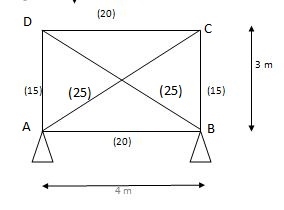
DSi = (M + R) – 2J
= (6+4) – 2 (4)
= 10 – 8
= 2
DSi (ext) = 1
(DSi) int = 1
2) Q = FAD (Tensile)
3) Figure
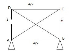
Sr. No. | Member | Length | Area | K | K2L/A
| Q | P = QK |
1. | AB | 4000 | 2000 | 4/3 | 3.56 |
| 11.86 |
2. | BC | 3000 | 1500 | 1 | 2 |
| 8.90 |
3. | CD | 4000 | 2000 | 4/3 | 3.56 | 8.90 | 11.86 |
4. | DA | 3000 | 1500 | 1 | 2 |
| - 8.90 |
5. | AC | 5000 | 2500 | -5/3 | 5.56 |
| -14.84 |
6. | BD | 5000 | 2500 | -5/3 | 5.56 |
| -14.84 |
|
|
|
|
|
|
|
|
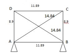
 Q = - Lt
∑ K2L/AE

 = - - 1.1. x 10-5 x 30 x 3000
22.24 / 200
= 8.90 KN (T)
Diagram
Q7) Explain the approximate methods of analysis of multi-storied multi-bay 2-D rigid jointed frames by Cantilever method?
A7) Portal method
This method is applicable for low rise structures. In low rise structures shear deformations are dominant, therefore this method simplifying assumptions regarding horizontal shear in column. Each bay of a structure as a portal frame and horizontal force is distributed equally among them. This means each interior column takes twice as much as the exterior column
Assumptions:
Steps
1) Assume first assumption -> mark point of contra flexure at centre of each column & beam
2) Apply 2nd assumption -> Horizontal shear is double at interior column.
3) Find P& Q force.
4) Find moment at beam = always same as moment of column.
5) Find shear force at beam=moment at 
Q8) Analyze the given figure by portal method
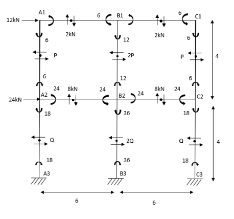
A8) Step 1) 1st Assumption-> Mark point of contra flexure of each member
Step 2) 2nd Assumption -> Interior Horizontal shear is double than (extreme) lost member.
P+2P+P=12
P=3KN
Q+2Q+Q=12+24
Q=9KN
Step 3) Moment at the end of column


Step 4) Moment at column


Step5) Moment at the end of roof Beam

Step 6) Moment at the end of floor Beam


Step 7) Shear force in Beam


Similarly, 

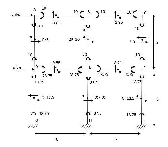
Q9) Analyze the given figure by portal Method
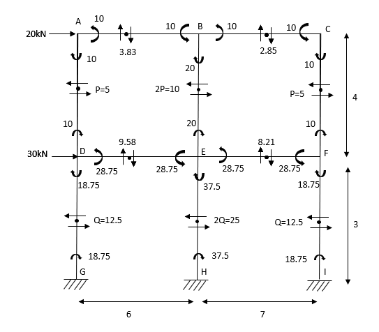
A9) Mark point of contra flexure at centre of each beam& column.
Horizontal share is double at interior column.
Find p & q
P+2P+P=20
P=5kN
Q +2Q +Q=50
Q=12.5KN
Moment at column AD= =
=
MBE=
MCF=
MDG=MGD=
MEH=MHE=
MFI=MIF=
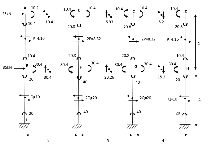
Q10) Analyze the given figure by portal method
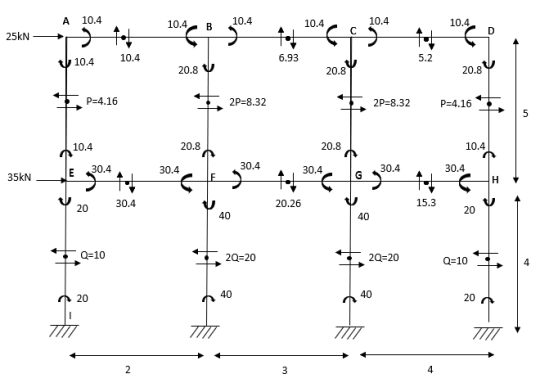
A10) P+2P+2P+P=25
4P=25
P=4.16
Q+2Q+2Q+Q=60
6Q=60
Q=10KN
MAE=MEA= =4.16
=4.16
MBF=MFB=
MCG=MGC=
MDH=MHD=
MEI=MIE= =10
=10
MFI=MIF=
MGK=MKG=
MHL=MLH=
Shear force
SFAB=20.8/2=10.4
SFBC=20.8/3=6.93
SFCD=20.8/4=5.2
SFEF=60.8/2=30.4
SFFG=60.8/3=20.26
SFGH=60.8/4=15.3
BMD
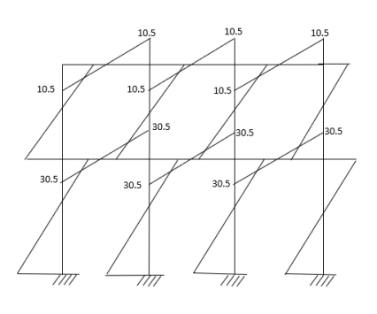
Q11) Analyze the given figure by portal method
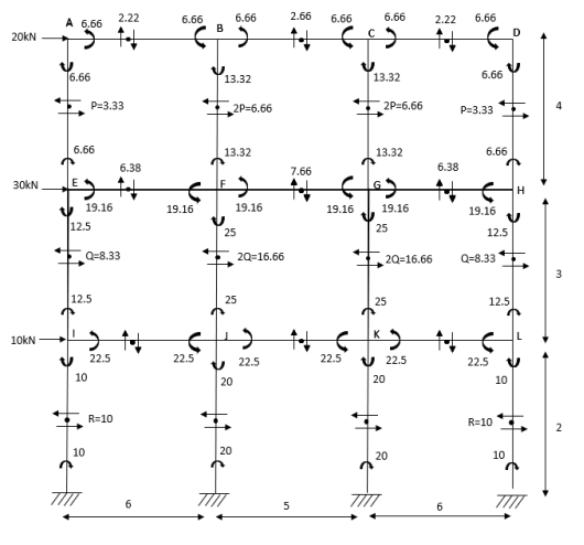
A11) P=3.33 Q=3.33 R=10


Q12) Analyze the frame shown in figure below by portal method
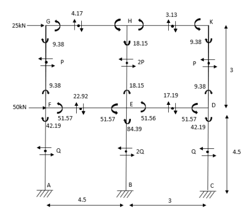
A12) 1) Apply 1st assumption
2) Apply 2nd Assumption-> Horizontal shear is double at interior member
P+2p+p=25
P=6.25KN
Q+2Q+Q=25+50
Q=18.75KN
3) Moment at the end of column


4) Moment at the end of floor column


5) Moment at beam

6) Moment at end of beam


7) Shear force at (beam) floor

Q13) What are the assumption and application of cantilever method?
A13) The cantilever method is based on the following assumption:
Assumption
Application:
Q14) Determine the approximate value of bending moment shearing force and axial force in a two bay two storey portal frame shown in fig. using cantilever method assume equal cross-sectional areas for all columns?
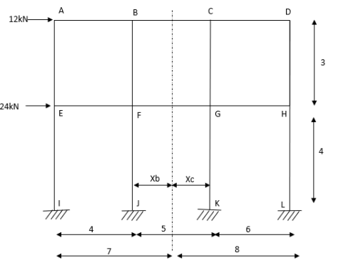
A14) Step-1 Find centroidal distance
Take moment about A


Step-2> As per 2nd assumption
Vertical stresses in column are proportional to their absence from the C.G. of the columns in that storey.
1> Consider top storey
Assume  is downward &
 is upward.
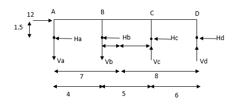


Put  values

Taken about point of contra flexure i.e., at 0 point
Clockwise +ve Anti clockwise -ve
Upward +ve Downward -ve


Consider lowest storey
Assume  are downward
 are upward
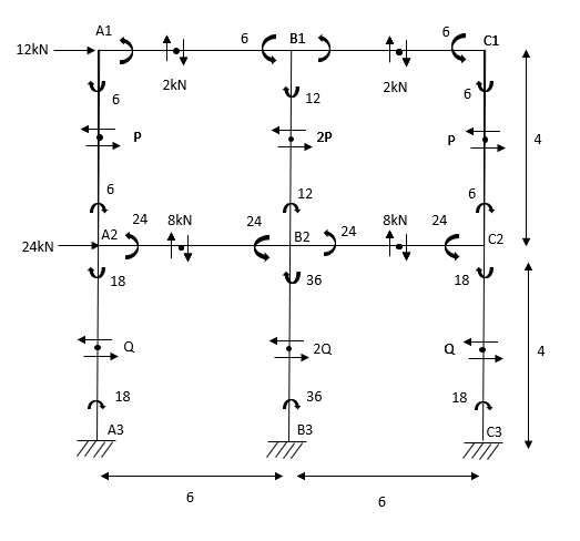
As per 2nd assumption


Take a moment about 0 point.


Step-3) To find S.F. in proof Beam
S.F. in AB=1KN
SF in BC=1+0.42=1.42
SF in CD=1+0.42-0.28=1.14
S.F. in EF=6-1=5KN
S.F. in FG=6+2.57+1-0.48=7.15KN
SF in GH=6+2.37-1.71-1-1-0.42+0.28=5.72KN
Step-4) To find Moment in roof beam
Formula => Moment in roof beam=S.F. in that Beam*Balt of Beam span


ii> To find moment in floor beam


Step -5) To find Moment in column


Moment in column of floor beam


Step-6) S.F. in column
S.F. AE=2/1.5=1.33KNM
SF BF=5.55/1.5=3.7KN
S.F. CG=6.9/1.5=4.6KN
S.F. DH=3.42/1.5=2.28KN
S.F. in column EI=1.33*1.5+x+2=10
X=4KN
S.F. in column FJ=3.725*1.5+x+2= (17.85+10)
X=11.128KN
S.F. in column GK=4.667*1.5+x*2= (17.14+17.85)
X=13.99KN
S.F. in column HL=2.28*1.5+x+2= (17.142)
X=6.86KN


