Unit - 3
Tacheometry and Contouring
Q1) Explain what do you mean by tacheometry and also application and limitation of same.
A1) Tacheometry:
Applications and Limitations:
Q2) What are the principle of stadia tacheometry?
A2) The principle of tacheometry is to enable horizontal and vertical distances to be computed from readings upon a stadia rod, and thus eliminate chaining operation.
1) The bearing of the line OP.
2) The angle of elevation or depression recorded on vertical circle of the instrument.
3) The readings of three diaphragm hairs upon a stadia rod at P sighted through thetelescope; top, middle and bottom.
Q3) Explain fixed hair method with vertical staff to determine horizontal distance and elevation point.
A3) It is not always possible to have a line of sight horizontal, while taking observations with tacheometer.
Case I: Line of sight is horizontal and the staff is held vertical.
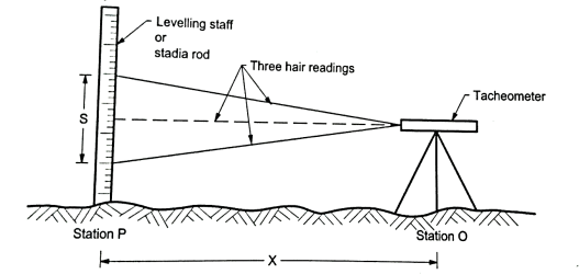
Fig: Line of sight is horizontal and the staff is held vertical
X= s + (f+c)
RL of station = RL of line of sight – axial hair reading
RL of line of sight= RL of Benchmrk + B.S
Case II: Line of sight is inclined and staff is held vertical.
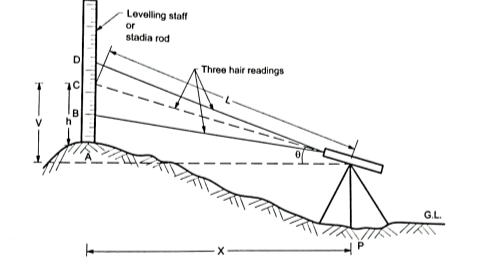
Fig: Line of sight is inclined and staff is held vertical

= S cos2
 +(f+c) sin

= S
S +(f+c) sin
Q4) How to find tacheometric constant? What is techeometric contouring?
A4)


Procedure:


Tacheometric Contouring:
1) Set up the tacheometer on the pinnacle of the steep hill. Tacheometer is a theodolite equipped with stadia diaphragm. The stadia diaphragm has 3 horizontal parallel hairs in preference to one as observed in a traditional move hair diaphragm.
2) With the assist of a tacheometer, it's far viable to decide the horizontal distance of the factor from the telescope as nicely its vertical degree.
3) The steep hill is surveyed at 3 levels – the bottom of the hill, the mid-degree of the hill and the pinnacle degree of the hill.
4) Using the tacheometer studying are taken all over the hill at identical angular durations on some of these 3 levels.
5) The radial plot therefore acquired is labored withinside the workplace to interpolate factors of identical elevation for contour mapping.
Q5) A tacheometer having constant 100 and 0.4 m readings were taken on vertical staff at station P and Q as follows:
Instrument Station | Staff station | Hair reading | Remark |
A | P Q | 1.200,2.300,3.400 0.300,2.100,3.900 | RL of P=100.00m |
Calculate the horizontal distance between A and Q and reduced level of Q. Assume line if sight horizontal.
A5) Step 1: The line of sight horizontal and staff is held vertical.
X= (S) + (f + c)
Step 2: The horizontal distance between O and A by observation at A
X =100 × (3.900-0.300) +0.4
X=360.4 m
Step 3: RL of instrument axis = RL of BM+ central hair reading
=100+2.3
=102.3 m
RL of Q = RL of instrument axis –central hair reading
= 102.3-2.1
=100.2 m
Q6) Explain contouring and define it.
A6) Contouring:
Definition of Contours:
A contour line:
Q7) What are the characteristics of contours.
A7)
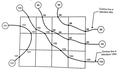
Fig: Contour lines of same elevation
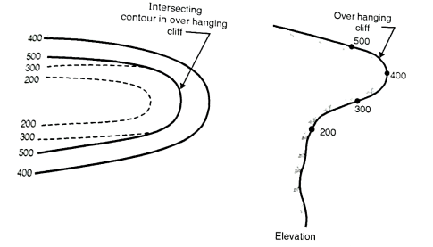
Fig: Intersecting contours in overhanging cliff
(i) When contour lines come close together then it indicates steep slope. Fig. showssteep slope along X-X.
(ii) Uniform slope: if contour lines are equally spaced, uniform slope is indicated.
(iii) A series of straight, parallel and equally spaced contours represent a plane surface.
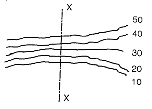
Fig: Steep slope along X-X
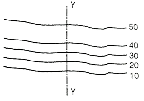
Fig: A gentle slope along Y-Y
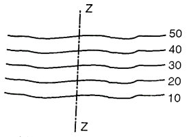
Fig: Uniform slope along Z-Z
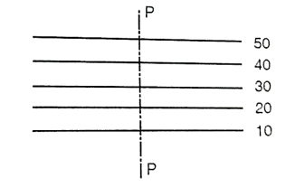
Fig: Plane surface slope along P-P
Depression: Closed contour lines with lower values inside indicate a depression.
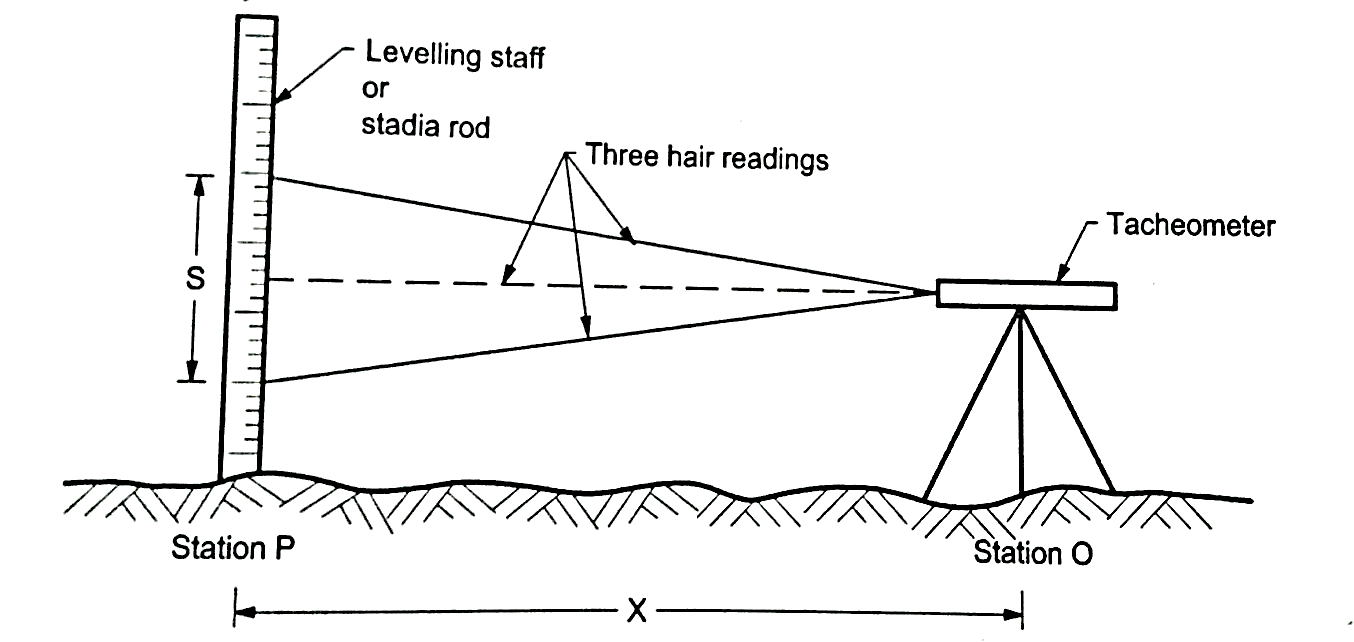
Fig: shows depression
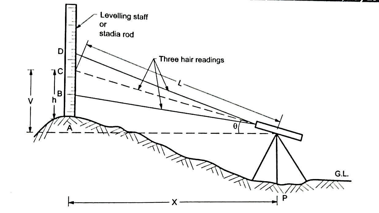
Fig: Shows a hill
Fig. indicates a ridge line. Contour lines cross ridge at right angles. For ridge line the higher elevation contour is inside the loop or band.
Valley line
Fig. indicates a valley line. Contour lines also cross the valley lines at rightangles. Valley line is indicated by higher elevation contours outside the loop.
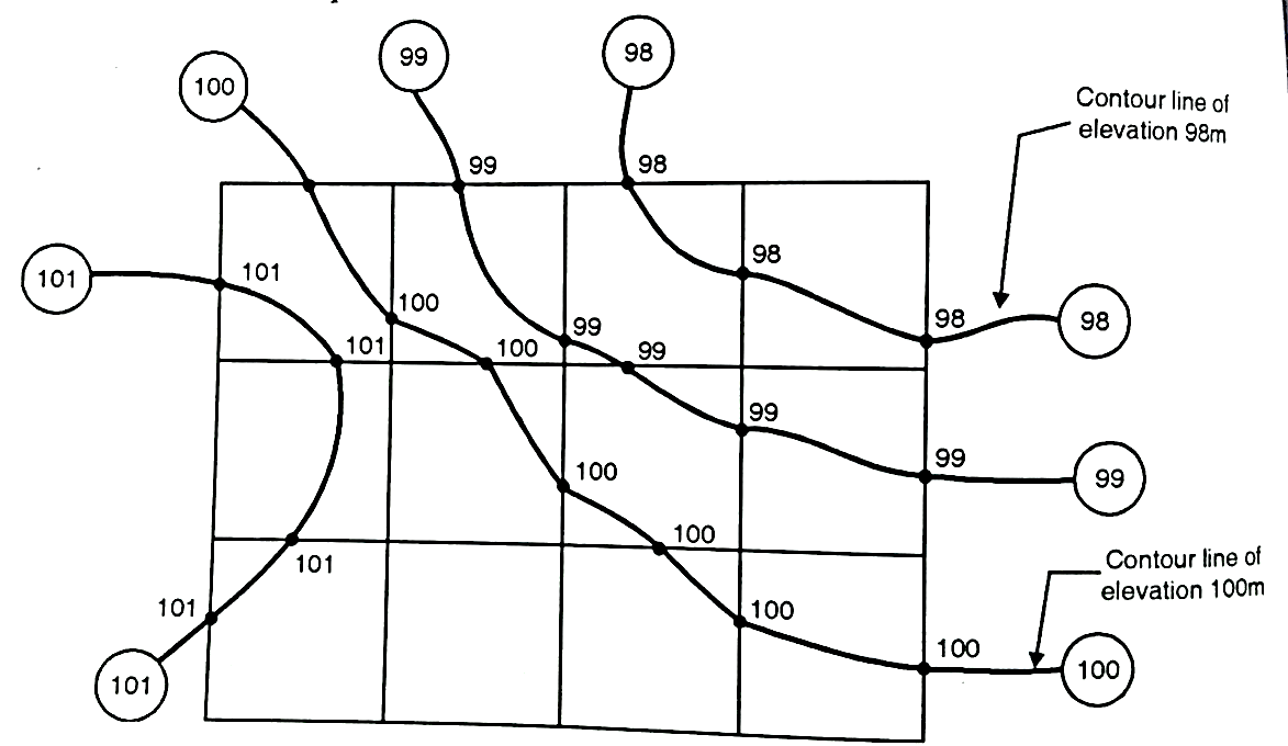
Fig: Ridge and valley line
Q8) Explain the direct method of contouring.
A8)
Procedure:
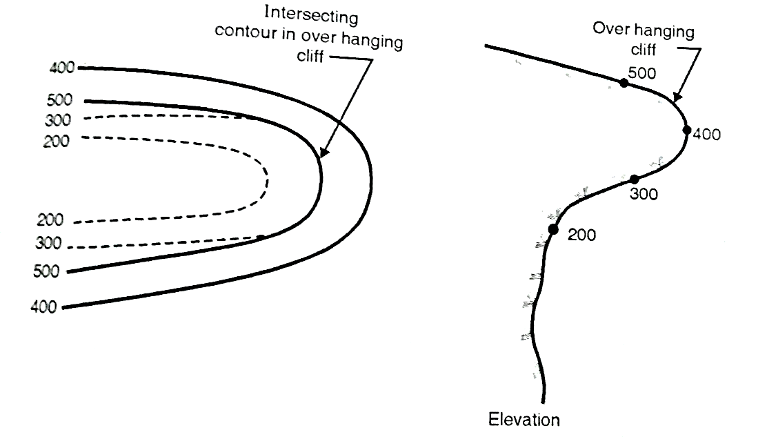
Fig: Direct method
(a)The work is started from B.M. and level is setup at the centre of the area.
(b) Suppose it is required to find out the contour of 90.000 m then the staff should be moved to various positions on plot where the reading on staff should give R.L. of 90.000 m. on ground. When all the points are located, they are marked on ground directly.
(c) Similar process is followed for locating the contour of 95.000 m and other contours.
Q9) Explain indirect method of contouring.
A9)
(a) By cross-section:
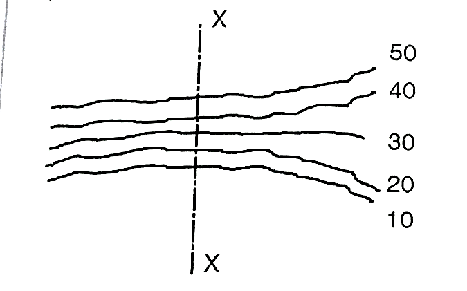
Fig: Method of cross-sections
(b) By squares:
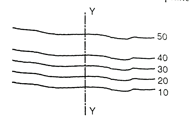
Fig.: Method of square
(c) By tacheometric method:
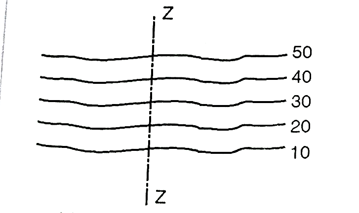
Fig: Tacheometric method
Q10) Give the use of contour maps.
A10) The important uses of contour maps are:
Intervisibility between two points:
Calculation of reservoir capacity:
Drawing of sections:
Location of Route:
Q11) Explain study and use of toposheets.
A11)
Uses of Toposheets:
Q12) What do you mean by profile leveling?
A12) The process of determining the elevations of points at measured intervals along a fixed line such as the centre line of a railway, highway, canal or sewer is known as profile levelling.
Objects: To determine the undulations of the ground surface along a given line for the alignment of canal, pipe line, road and railway.
Field procedure:
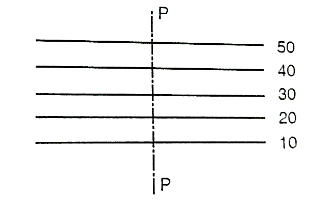
Fig: Profile leveling
2. Mark point at 10 m intervals on this line.
3. Level is set up on a firm ground at a suitable point I1
4. Temporary adjustment of level is done and B.S is taken on the B.M.
5. The RL of collimation (HI) is worked out by adding B.S. to the R.L. of B.M. the chain is stretched from P toward the point B.
6. Also, the staff readings are taken at 10 m points, and entered in the I.S column againstthe respective chainages.
7. Besides these points, the staff readings are taken at the representative points for exampleslope of ground surface changes appreciably.
8. When it is found necessary to shift the instruments on account of the length ofsightexceeding about 100 m or the further points not being possible to be observed owing the irregularities of the ground, CP, is taken at suitable position, and F.S is taken on it and entered in F.S column.
9. The instrument is then shifted and set up on firm ground at I2, as before.
10. B.S is taken on CP1, and new HI is calculated.
11. Chaining and readings are then continued as before until the reading is obtained at thelasp point R.
12. B.M should be checked during the progress of the work.
13. Therefore, bearing of the line PQ, QR etc are taken with compass at start and noted in the field book.
14. Neat sketches of Bench Marks and the features such as nalla, road crossing etc should be drawn in the field book with full description.
Important points to be remembered while running a profile:
Plotting Profile Levelling:
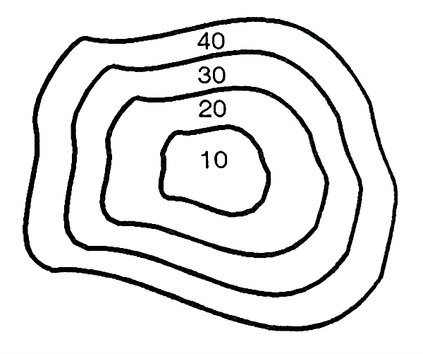
Fig: Plotting profile level
Q13) Give the cross section of profile leveling.
A13)
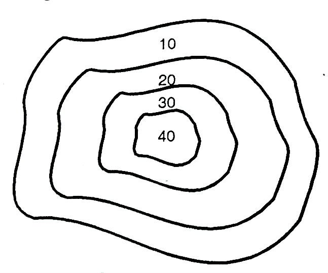
Fig.: Cross-section
Plotting the Cross Section:
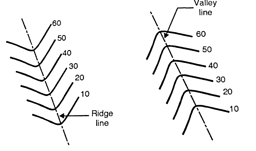
Fig: Plotting cross section