Unit - 3
Eccentric Loaded Columns and Column Bases
Q1) Explain Design of eccentrically loaded column providing uniaxial and biaxial bending for section strength?
A1)
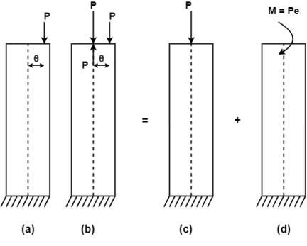
Eccentric Loading:
- The load whose line of action does not coincide with the axis of column is called as an eccentric loading. It produces buckling of column.
- Due to eccentric load, both direct stress and bending stress induced.
Combined maximum stress = direct stress  bending stress
Maximum stress  =
=  +
+  ( Compressive)
Minimum Stress  =
=  -
-  (Tensile)

Bi- Axial Bending
A column is a vertical structural member designed to transfer a compressive load. For example, a column might transfer loads from a ceiling, floor or roof slab or from a beam, to the foundations.
Columns also carry the bending moment about one or both axes of their cross-section.
Biaxial bending affects columns where the load is eccentric about both the axes in the plane of the column (eccentric load is a force placed upon a portion of a column which is not symmetric with its central axis, thereby producing bending).
For both rectangular and square columns, there are situations in which axial compression is accompanied by simultaneous bending about both principal axes of the section.
BIAXIAL BENDING IN COLUMNS
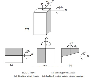
Columns are usually subjected to two bending moments about two perpendicular axes (X and Y) as well as an axial force in the vertical Z direction (see Figure 1).

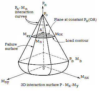
With the shown sign convention, bending about X-axis causes compression in the top part and tension in the bottom region, whereas bending about Y-axis causes compression in the left-hand part and tension in the right part. For symmetric sections subjected to uniaxial bending, the neutral axis is parallel to the moment axis. In biaxial bending (d), the top-left part is subjected to double compression and the bottom right part is subjected to double tension. The remaining parts are subjected to combined compression and tension. This means that the two moments are not X Y Mx My P Y My X Mx (b) (c) (d) X Y Mx My independent but coupled. The resulting neutral axis is inclined with an angle depending on the moment values as well as the section properties. Interaction between the axial force P and the two bending moments Mx and My is represented by a 3D surface. The design surface is inside the nominal surface. The 3D surface is constructed by combining several interaction curves P-M at various neutral axis angles.

Various 2D scans can be extracted from the 3D surface:
- Horizontal scan giving interaction curve Mx – My for a given value of the axial force P, also called load contour.
- Vertical scan giving interaction curve P – Mx for a given value of My moment.
- Vertical scan giving interaction curve P – My for a given value of Mx moment.

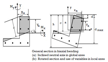
The figure shows a general section subjected to biaxial bending. With respect to the sign convention shown in the figure, the nominal force and moments in biaxial bending are given by:

B is the area of the concrete compression block. Xb and Yb are coordinates of the centroid of the compression block with respect to X and Y axes having the origin as the centroid of the gross section. Steel bars are described by their coordinates Xsi and Ysi. The compression block may have more than one part as and may contain parts of the possible voids present in the section. For each neutral axis angle, an interaction curve (meridian) P-Mx-My is constructed by varying the neutral axis depth from pure compression to pure tension. Calculations are complex and are usually carried out in local axes (b).
Biaxial bending analysis and design of columns is very complex and only some specific software can be used for this purpose such as RC-BIAX developed in KSU. Codes of practice such as ACI and SBC allow the use of approximate methods to check for biaxial bending. Among these is the reciprocal method of Bresler.
A column is a vertical structural member designed to transfer a compressive load. For example, a column might transfer loads from a ceiling, floor or roof slab or from a beam, to the foundations.
Columns also carry the bending moment about one or both axes of their cross-section.
Biaxial bending affects columns where the load is eccentric about both the axes in the plane of the column (eccentric load is a force placed upon a portion of a column which is not symmetric with its central axis, thereby producing bending).
For both rectangular and square columns, there are situations in which axial compression is accompanied by simultaneous bending about both principal axes of the section.
Design of Column Section
This chapter deals primarily with the IS code provisions for the design of columns, under various loading conditions. The design of column section can be made either by working stress method or by limit state method. The working stress method of design of column is based on the behaviour of structure at working loads ensuring that stresses in steel and concrete do not exceed their allowable values. The section is assumed to possess adequate safety against collapse. The limit state method of design of column is based on behaviour of structure at collapse, ensuring adequate margin of safety. The serviceability limits of deflection and cracking are assumed to be satisfied as columns, being compression members, have very small deflection and cracks.
Assumptions in Limit State Method Following are the basic assumptions in the Limit State Method. 1. The plane section normal to the axis of column before deformation, remains plane after deformation i.e., the strain at any point is proportional to its distance from the neutral axis. 2. The tensile strength of concrete is ignored. 3. The maximum compressive strain in concrete in axial compression is taken as 0.002. 4. The relationship between stress-strain distribution in concrete is assumed to be parabolic as shown in Fig.2.1. The maximum compressive stress is equal to 0.67 fck/ 1.5 or 0.446 fck, where 1.5 is the partial safety factor for concrete. 5. The stresses in reinforcement are derived from the representative actual stress-strain curve for the type of steel used. The partial factor of safely of 1.15 is taken for steel. Therefore, design strength is 0.87 fy, as shown in Fig.2.2. 6. The maximum compressive strain at the highly compressed extreme fibre in concrete subjected to axial compression and bending, but when there is no tension on the section, is taken as 0.0035 minus 0.75 times the strain at the least compressed extreme fibre.
The maximum compressive strain at the highly compressed extreme fibre in concrete subjected to axial compression and bending, when part of the section is in tension, is taken as 0.0035. Other codal provisions based on 15:456-2000 are as follows:
Minimum Eccentricity: - All columns in compression shall be designed for the minimum eccentricity
Emin = Unsupported Length / 500 + Lateral Dimension/30, Subject to a minimum of 20 mm. 2.3 Short Columns Under Axial Compression When the minimum eccentricity given by above equation is less than 0.05 times the lateral dimension, the members may be designed by the following equation.
Pu = 0.4 fck *Ac + 0.67 fy *Asc.
The above equation can be written as
Pu = 0.4 fck (Ag - p*Ag / 100) + 0.67 fy* p*Ag/100 or Pu / Ag = 0.4 fck (1 - p/100) + 0.67 fy* p / 100 or P„ /Ag - 0.4 fck + p/100 (0.67 fy - 0.4 fck)
Where p = Percentage of total steel in section. Fy = Characteristic strength of steel
Ag - Gross (iii; a of concrete section = b*D for rectangular section. - (7i*dia.*dia.)/4 for circular section
Fck - Characteristic strength of concrete in 'SP-16',
Chart No. 24-26 are given for designing short columns in accordance with above equation.
Q2) Explain Design of column bases: slab base, gusseted base and moment resistant base for axial load and uni-axial bending?
A2)
The columns are supported at the column bases. The column bases transmit the column load to the concrete or masonry basis blocks.
The column load is unfolded over massive location on concrete or masonry blocks. The depth of bearing stress on concrete or masonry is stored inside the most permissible bearing stress.
The protection of the shape relies upon up on balance of basis. The column bases need to be designed with utmost care and skill. In the column bases, depth of stress on concrete block is thought to be uniform.
The column bases will be of ok strength, stiffness and location to unfold the burden upon the concrete, masonry, different basis or different helps without exceeding the allowable strain on such basis below any mixture of the burden and bending moments.
The column bases are of types;
- Slab base
- Gusseted bases
1. Slab base
The column give up is confronted for bearing over the complete area. The gussets (gusset plates and gusset angles) aren't supplied with the column with slab bases. The enough fastenings are used to hold the elements securely in plate and to withstand all moments and forces, apart from the direct compression. The forces and moments springing up all through transit, unloading and erection also are considered. When the slab by myself distributes the weight uniformly the minimal thickness of a square slab is derived as below;
Procedure
Step 1) Assume a suitable grade of concrete. Depending upon the grade of concrete used bearing strength of concrete is determine by 0.45fck
Step 2) The area of a slab base may be computed by
A= P/ bearing strength of concrete
Where,
A= area of base plate
P= Factored load
Step 3) A square base plate is generally provided. The side of the base plate may be worked out
L= B= 
Some designer feels that the projections of the base plate beyond column edges a and b are kept equal and these sides can be work out.
Using
(D+2b) x (bf+2a) = A
Where,
L= length of base plate in mm
B= width of base plate in mm
D= depth of column section in mm
Step 4) The intensity of pressure w from the concrete pedestal is determine by
W= P/A1
Where, w= intensity of pressure from concrete under the slab base
A1= Area of base plate provided in mm2
Step 5) The minimum thickness ts of the base plate is calculated by using

Step 6) Holding down bolts 2 or 4 in number and of 20 mm diameter are usually provided. When the base subjected to only axial compressive load two bolt will be enough.
Step 7) welded joint between the column and base plate is designed.
Step 8) Detailing
2. Gusseted base
Procedure
Step 1) Bearing strength of concrete is determined = 0.45 f
Step 2) Area of the base plate may be computed by,
A = P/0.45 fck
Step 3) The size of gusset base assumed
(i) Thickness: For bolted gusset base t <16 mm.
(ii) The gusset angle is chosen so as to accommodate two rows of bolts in the vertical leg and one row of bolt in the horizontal leg. Therefore, an unequal angle section is provided.
(iii) The thickness of gusset angle should be same as thickness of gusset plate.
(iv) Width of base plate.
L = depth of section + 2 (thickness of gusset plate +leg length of angle + over hang) (for bolted connections)
L = depth of section + 2x (thickness of gusset plate + overhang)
(For welded connections)
(v) Width of base plate
B = A/L
Step 4) The intensity of bearing pressure
W = P/A1
Where
A₁ = Area of base plate provided
Step 5) The thickness of the base plate is computed by equating the moment at the critical section to the moment of resistance of the gusset at that section.
B.M. At critical section
M = wc12/2(considering unit width)
Where
c.- Minimum over hang
Design bending moment at critical section M, 12

Now equating, M = Md


Where,
t= Total thickness including thickness of base plate and gusset angle (for bolted gusset base)
= Thickness of base plates (for welded gusset base)
W= Intensity of pressure from concrete under the slab faze.
C₁=Cantilever portion of base plate
Step 6) Holding down bolts 2 or 4 in numbers and of 20 diameter are usually provided.
Step 7) Design connection
Step 8) Detailing
Q3) Design a slab base for the column consisting of ISMB 400@ 61.6 kg/m carrying an axial factored load of 450kN. Use M20 grade of concrete.
A3)
- Area of base plate


2. Size of base plate
Provide 430 x 170 mm size of base plate
Area provide = 73100> A required
3. Intensity of pressure w from concrete pedestal
w = P/A provides


4. Thickness of base plate (ts)

Provides base plate of size 430 x 170 x 16 mm
Q4) Design a slab base for a column ISHB 350 @ 67.4 kg/m carrying a factored load of 1000 kN. Also design the welded connection between slab base and column. Use concrete grade M20 and Steel of Fe410
A4)
- Bearing Strength of concrete

2. Area of base plate

3. Size of base plate
Provide 410 x 310 size of base plate

4. Intensity of pressure w from concrete pedestal

Projection


5. Thickness of base plate

Thickness of flange of ISHB 350 @ 67.4 kg/m is 11.6 mm
Provide 410 x 310 x1 2 mm plate to carry load
6. Design of anchor bolts
Use a bolts of 20 mm diameter of 300 mm long to anchor the plates
7. Design fillet weld column is fixed over a base plate
Using fillet weld of column is fixed over a base plate
Total length available for welded

Strength of weld

Let a be the size of weld
Then effective area of weld = 0.7 x a x Le
Equating to the strength by assuming the size of weld 6 mm


Available effective length


Hence Provide 6 mm size of fillet weld
Q5) Design the section of steel column and suitable base for an axial compressive factor load of 3000 kN. The effective length of column is 6 m The grade of concrete used for pedestal is M30.
A5)
- Factored load P
P= 3000 KN
KL= 6000 mm
Fy = 250 MPa
Assuming Fcd = 200 MPa
2. Selection of section
Area of required = 
Provided built up section 2 ISLC 400 @ 45.7 kg/m with cover plate of 420 X6 mm shown in
Properties
A= 5825 mm^2
D = 400 mm
Bf = 100 mm
Tf = 14 mm
Tw = 8 mm
C = 23.6 mm
Izz = 11989.5 x 10 ^4 mm^4
Iyy= 460.4 x 10^4 mm^4
Area Provided
5825x2+2x420x6 = 16690 mm^2 > A required
3. Design strength (pd)
Slenderness ratio = 
Buckling class for built up section is C
Using table 9(c)
Design compressive stress
Fcd = 202.47 MPa
Design strength (pd) = Ae x Fcd = 16690 X 202.47 = 3379.2 kN
4. Design of slab base
As M30 grade concrete used for pedestal
Required area of base plate

Providing nominal cleat angle of 65 x 65 x 8 mm
Minimum width of base plate
2x65 + 420 = 550 mm
Length of base plate L = 460 mm
Area of base plate provided = 550 x 460
A1= 253000 mm^2 > Area Required
Bearing pressure of concrete on base plate

Projections


Thickness of base plate

Hence Safe
Provide base of size 550 x 460 x 24 mm Thick
Q6) Design a slab base for the column consisting of ISWB 300 @ 48. 1kg/m carrying an axial factored load of 1100 KN. Design welded connection between column and base plate. Concrete of grade M20 is available.
A6)
Design of slab base for column ISWB 300 @ 48.1kg/m
- Factored load P = 1100 KN
- Bearing strength of concrete
= 0.45 fck = 0.45 x 20 = 9 N/mm^2
3. Size of base plate

Provide size of base plate 410 x 310 mm
4. Thickness of base plate

Projections


Thickness of base plate

Provided 410 x310 x 16 mm plate for slab base
5. Design of welded connection
Length of weld available

Assuming size of weld 6 mm


Available effective length
= 1365.2 – 2 x 6 x12 = 1221.2 mm < Lw required
Unsafe
Hence provide 9 mm size of fillet weld for a 1200 mm length
Q7) Design a base plate for column of ISHB 250 @ 51.0 kg/m carrying a factored load of 650 KN. Assume that the column is supported on a concrete of grade M 25
A7)
- Bearing strength of concrete
0.45 fck = = 0.45 x 25 = 11.25 MPa
Area of base plate

2. Size of base plate


3. Intensity of pressure w from concrete pedestal

Projections


4. Thickness of base plate

Thickness of flange of ISHB 250 @ 51 kg/m is 9.7 mm
Provide ts = 10 mm thick base plate
Provides base plate of size 310 x 310 x 10 mm
Plate to carry load safety
Q8) Explain types of column bases and design the size of slab for a column ISHB 350 @ 67.4 kg/m supporting a factored axial compression of 1200KN consider grade of concrete as M20
A8)
1.Geometrical properties of ISHB 350 @ 67.4 kg.m
h = 350 mm
Bf = 250 mm
Tf = 11.6 mm
8.3 mm
2.Size of base plate
Area required =

Select 420 x 380 mm size of base plate
Area provided= 420 x 380
= 15.96 x 10^4 mm^2 > A required
3.Bearing pressure a base plate

4. Thickness of base plate
Assume


Provide base plate of size 420 x 380 x 12 mm for slab base