Unit - 5
Design of Industrial truss and Gantry Girder
Q1) Explain Roof truss: assessment of dead load, live load and wind load?
A1)
Auditoriums, assembly halls, workshops, warehouses, industrial sheds etc. required large column free areas.
To get such areas, the commonly used roofing system is to be provided as a set of steel roof trusses, interconnected with purlins which supports GI (Galvanized Iron) or A.C. (Asbestos Cement) sheet.
A typical industrial building with its components is shown in Fig.
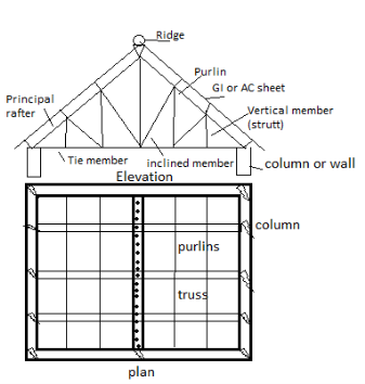
The nomenclature used for the various members of a truss are described given below
- Top chord members:
These are the members along the uppermost line of roof truss starting from one end of support to another end and passing through ridge.
These members are also called principle rafters which directly support to purlins. They are mainly subjected to axial compression due to dead loads and live loads.
If the purlins are not supported at joint then these members are subjected to bending stresses also.
2. Bottom chord members
These are the members extending from one end of support to another end along the lowermost line of truss. These members are also known as main ties. They are mainly subjected to tensile forces due to dead loads and live loads.
3. Struts
The members which do not belong to top or bottom chord and subjected to compressive forces are called struts,
4. Slings
The members which do not belong to top or bottom chord but are mainly subjected to tension are called slings.
5. Sag tie
If no load is in the member and usually they provided to reduce the sag in the adjacent member is called sag tie.
Types of Roof truss
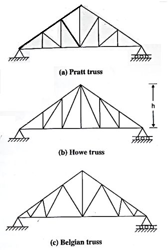
The types of roof truss depend upon the fancy of the architect and upon the demands of the particular building for which it is used. Some typical roof trusses are shown in Fig. Fink truss provided for large pitch, Pratt and Howe truss for medium pitch and warren truss provided for small pitch respectively.
Geometry of roof truss
- Pitch of truss
It is defined as the ratio of the height of truss to the span. The minimum pitch is to be maintained for G.L sheet covering is of 1/6 and for AC sheet 1/12
2. Spacing between trusses
The distance between the two consecutive trusses is called spacing of truss. As spacing of two increases, the number of trusses may reduce cont of purlins increases. The following g may be used to decide the spacing trusses
Spacing of truss = 1/3 to 1/5 span of truss
= Span/4 (up to 20 m span)
3. Purling
As far as possible purlins should be loading panel points of top chord members. However, depends upon the type and length of mofag materials also. Generally, the spacing of purling varies from 1.35 to 2.0 m. Angle sections are u for smaller value of trusses (3 to 4 m) for mode sizes (4 to 5 m) channel section or I section can be preferred.
4. Central rise
Central top part of truss is called ridge time and central rise is called height of truss. Generally, it is Span/5 to Span/6 provided
5. Sheeting
(1) GI sheets: Galvanized iron sheets und protection against corrosion. The common size of GI sheet is (From 275 p Table 5)
(a) 8 corrugations 75 a 19 depth with overall width of 660 mm.
(b) 10 corrugations 75 x 19-man dog seith overall width of 810 mm
(c) Length available are 18, 22, 23, 24 and 3 m
(2) AC sheets: Asbestos cement sheets are better insulators for sun's beat compared to Gl sheet. They are used only for factories and godowns. They are available in lengths of 1.75, 2, 2.5 and 3 m.
Q2) Explain Load calculation of roof truss?
A2)
The main loads on trusses are:
- Dead loads
- Imposed loads (live loads)
- Wind load
- Other loads
- Dead load
Dead loads include the weight of roof sheeting. Purlins, bracings, self-weight of truss and other loads suspended from trusses.
The unit weight of various materials is given in IS875 part I. The following values may be noted:
(a) AC sheet:
Corrugated (pitch=146 mm) = 118 to 130 N/m²
Semi-corrugated (pitch = 340 mm) = 118 to 127 N/m² Plain = 102 N/m²
(b) GI sheet: 85 N/mm²
In general, the roof covering weight including laps, connector etc. may be taken as
GI sheet: 100-150 N/m² = 130 N/m²
AC sheet: 170-200 N/m² = 180 N/m
(c) Weight of purling: 100-120 N/m²
(d) Self weight of truss for span L W 10+5) N/m² =10
Where,
S= spacing of trusses
L = span of truss
2. Imposed load (Live load)
Normally no access is provided for sloping roofs with sheets. In such cases IS 875 part II makes provision for the design of sheets and purlin are: Live load (LL): (Table-2 IS 875-part-2)
- Up to 10° slope; LL = 0.75 kN/m²
- From more than 10° slope, LL = 0.75 -0.02 (a-10)
Where a is slope of sheeting for the design of truss the above live load may be reduced to
3. Wind load
IS 875 part 3 gives guide lines to determine wind forces on different components of buildings. If consist of the following steps.
Determine basic wind speed:
(Cl.52 and Appendix A of IS 875 part 3) for finding basic wind pressure in any place in India, IS 875 part-3 divides the country into six zones. It is based on peak velocity averaged over a short time interval of about 3 seconds studied over a period of 50 years.
The values correspond to the speed at 10 m height above ground level and in an open terrain. It may be observed that highest basic wind speed is 55 m/s and the lowest is 33 m/s.
Q3) What is Design of purlin?
A3)
Purlins are horizontal beams which are used for structural guide in buildings. Most commonly, purlins are primary additives of roof structures. Roof purlins are supported both with the aid of using rafters or constructing partitions and the roof deck is laid over the purlins. As a result, they have a tendency to be used for large-scale structures
Purlins are horizontal beams which can be used for structural assist in buildings. Most commonly, purlins are important additives of roof structures. Roof purlins are supported both through rafters or constructing partitions and the roof deck is laid over the purlins.
Traditional wooden framing consists of 3 primary purlin types; the not unusual place purlin, the purlin plate and the essential purlin. Purlins may be manufactured from some of one of a kind substances and are to be had in some of one of a kind types:
C purlins: The form of those varieties of purlins is that of a square 'C'. C purlins are used as purlins over partitions, rafters, ground joists and studs for partitions.
Z purlins: Z purlins resemble the alphabet Z and also are known as Zed Purlins. This form enables the purlins to overlap joint and is more potent and studier than the C purlins.
As a result, they have a tendency to be used for large-scale structures.
RHS purlins: For roofs wherein the assist shape is seen as soon as the development is complete, RHS purlins can be used (square hole section). These purlins are essentially hole, square tubes, with welded ends so there's no metallic bar corrosion, harm or seepage.
Purlins are to be had in type of substances relying on budget, structural and aesthetic requirements. The maximum conventional fabric for purlins is wood. However metallic roof purlins and galvanized purlins can provide advantages of durability, price and structural strength. Cold fashioned metallic and the recent rolled metallic techniques may be used to create the specified shapes from the metallic sheets.
Principal purlin Principal purlins in timber construction, additionally called "foremost purlins" and "aspect purlins," are supported through foremost rafters and aid not unusual place rafters in what's referred to as a "double roof" (a roof framed with a layer of foremost rafters and a layer of not unusual place rafters).
Principal purlins are similarly categorized through how they connect with the foremost rafters: "via purlins" by skip over the top; "butt purlins" ten into the edges of the foremost rafters; and "clasped purlins," of which best one anciently U.S. Instance is known, [citation needed]) are captured through a collar beam. Through purlins are similarly classified as “trenched,” “back,” or “clasped;” butt purlins are categorized as “threaded,” “tanned,” and/or [clarification needed] “staggered
Q4) Explain Design of members of a truss, detailing of typical joints and supports?
A4)
- Pitch of truss
It is defined as the ratio of the height of truss to the span. The minimum pitch is to be maintained for G.L sheet covering is of 1/6 and for AC sheet 1/12
2. Spacing between trusses
The distance between the two consecutive trusses is called spacing of truss. As spacing of two increases, the number of trusses may reduce cont of purlins increases. The following g may be used to decide the spacing trusses
Spacing of truss = 1/3 to 1/5 span of truss
= Span/4 (up to 20 m span)
3. Purling
As far as possible purlins should be loading panel points of top chord members. However, depends upon the type and length of mofag materials also. Generally, the spacing of purling varies from 1.35 to 2.0 m. Angle sections are u for smaller value of trusses (3 to 4 m) for mode sizes (4 to 5 m) channel section or I section can be preferred.
4. Central rise
Central top part of truss is called ridge time and central rise is called height of truss. Generally, it is Span/5 to Span/6 provided
5. Sheeting
(1) GI sheets: Galvanized iron sheets und protection against corrosion. The common size of GI sheet is (From 275 p Table 5)
(a) 8 corrugations 75 a 19 depth with overall width of 660 mm.
(b) 10 corrugations 75 x 19-man dog seith overall width of 810 mm
(c) Length available are 18, 22, 23, 24 and 3 m
(2) AC sheets: Asbestos cement sheets are better insulators for sun's beat compared to Gl sheet. They are used only for factories and godowns. They are available in lengths of 1.75, 2, 2.5 and 3 m.
6. Load calculation
a. Dead load
b. Live load
c. Wind load
d. Other load
Q5) Explain Design of gantry girder: selection and design of cross section, check for moment capacity, buckling resistance, bi-axial bending, serviceability and fatigue strength?
A5)
The gantry girders are girders which helps the hundreds which might be transmitted via the journeying wheels of the crane. The crane girder spans from column to column, this typically do now no longer have any lateral help on the intermediate factors excepting whilst a walkway is shaped on the pinnacle of the girder.
Overhead journeying cranes are utilized in business homes to raise and delivery heavy jobs, machines, and so on, from one region to another.
The crane can be a manually (hand) operated overhead travelling crane (M.O.T.) or an electrically operated overhead travelling crane (E.O.T.). A standard association of a crane gadget is proven below. Usually, the crane includes a bridge made from truss girders.
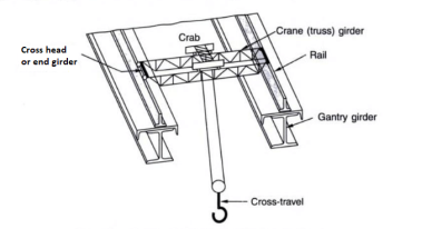
The bridge is called a crane bridge, crane girder, or crab girder. It spans the bay of the store and actions in a longitudinal direction. To facilitate movement, wheels are connected to the ends of crane girders. These wheels pass over rails positioned centrally over the girders that are known as gantry or crane gantry girders. These girders are designed as laterally unsupported beams till the compression flange is laterally supported with the aid of using both a catwalk or with the aid of using a further member. Show under fig. The front view and pinnacle view of the everyday association of a crane girder, gantry girder, and column in a workshop.
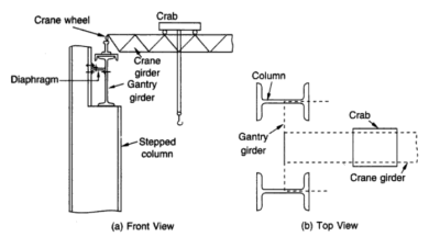
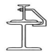
A trolley (crab) with wheels and a suspended hook is located over the crane bridge and this association can flow within side the transverse direction. However, it needs to be stated that the 2 actions of the crane, the longitudinal and the transverse cannot be had simultaneously. Bolted clamps or hook bolts are, used to maintain the rails in position.
Types of Loads on Gantry Gutter:
1) Vertical Loads on Gantry Gutter
2) Lateral Loads on Gantry Gutter.
3) Longitudinal Loads on Gantry Gutter
4) Impact Loads on Gantry Gutter.
- Vertical Loads on Gantry Gutter-
A vertical load appearing over the gantry girder is the response from the crane girder and includes the self-weight of the crane, self-weight of the crab, and the crane capacity (the most load that may be hoisted). To calculate the response the most wheel load is computed. It happens whilst the crab is nearest to the gantry girder. In addition to the response from a crane girder, the self-weight of the rail needs to additionally be considered.
2. Lateral Loads on Gantry Gutter-
Lateral forces on crane girders can be resulting from the (a) Thrust because of the unexpected preventing of the crab and cargo whilst traversing the crab girders (b) Crab dragging weights throughout the store floor. The foregoing instances cannot arise simultaneously.
In (a) As with the longitudinal gantry girders, the frictional resistance of the rail is transferred into the crab girders and from them into the crosshead girders, thence, as factor hundreds thru the principle wheels, into the pinnacle or compression flanges of the gantry girders. The positions of the principle wheels whilst most lateral bending and shear take area at the gantry girder may be similar to the ones whilst most vertical bending second and shear happens.
(b) The crane is regularly requisitioned to tug weights throughout the store floor. If the weight is extraordinarily massive, it's also hooked up on kind of long-established rollers, in all likelihood jogging on a wood plank track. The lateral thrust and pull at the compressive flanges of the gantry girders then grow to be a count number of conjectures. The resisting forces are, firstly, the friction of the principle wheel treads upon the gantry rails and, secondly, the forces supplied through the flanges of the principle wheels bearing in opposition to the gantry rails. The lateral thrust is thought to behave within side the aircraft of the middle of gravity of the top flange.
Acting because it does on the rail level, it has genuinely a lever arm generating torque. This small lever arm and, therefore, the torque are neglected. No assistance is assumed to be afforded through the decrease or tensile flange in resisting lateral thrust. However, need to this assist be considered, then the torque because of the thrust elevated through the space from the road of movement of the thrust to the N.A. (n on this case)—need to additionally be taken into consideration.
3. Longitudinal Loads on Gantry Gutter-
Longitudinal masses are triggered because of the preventing or beginning of the crane girders and bring a thrust alongside the rails. The biggest of those, specifically in quick-appearing electric powered overhead journeying cranes, is because of the unexpected software of the brakes.
The frictional resistance to the sliding of the locked wheels upon the rails is furnished with the aid of using the crane girder. This detail in flip distributes it among all of the crane column shafts. The lateral and longitudinal thrusts are transferred on the rail level. Therefore, gantry girders also are subjected to bending moments because of those masses.
4. Impact Loads
The stresses produced in gantry girders because of the above hundreds are greater than the ones because of regularly implemented hundreds. This is because of the force’s installation through the surprising software of brakes to the hastily transferring loaded cranes acceleration, retardation, vibration, viable slip of slings, etc.
The steelwork which consists of those quick-appearing cranes have to be heavier than the steelwork which helps slow-transferring cranes. With quick-appearing electric powered overhead traveling (E.O.T) cranes, the stresses within side the gantry girders are produced nearly instantaneously, while with slow-transferring hand-operated cranes, the bending stresses within side the girder are brought about regularly from 0 as much as their most values, because the cranes traverse the girder from the give up in the direction of the center.
Q6) Explain design steps of gantry girder?
A6)
1) Determine maximum wheel load
By considering the crab is closet to gantry girder. The vertical reaction of the crane girder is transferred through its two wheels on to the gantry girder.
2) Determine maximum bending moment in the gantry girder.
3) Determine maximum shear force developed between wheel load and dead loads.
4) Determine lateral force on the girder and the maximum bending moments and shear due to these.
5) Selection of section and plastic sectional modulus is determined.

6) Classification of section
Using table 2 of IS 800-2007 both I and channel section is classified
7) Check for moment capacity
- For laterally supported girders

b. For laterally supported girder

8) Check for local moment of flange

9) Check for buckling resistance


10) Check for shear

11) Check for buckling of web
Buckling resistance

12) The girder is checked for bearing if required bearing stiffener are provided
13) Connection of channel to the I section are designed.
14) Check for deflection

15) Check for fatigue strength
16) Design connection of bracket to column
Q7) Design a cross section for simply supported gantry girder to carry electric overhead travelling crane for the following data. Design section should be checked for moment capacity, local capacity, shear capacity, web buckling and deflection
Crane capacity = 280 KN
Weight of crane excluding trolley = 150 KN
Weight of trolley = 120 KN
Minimum approach of crane hook = 1.0 m
Wheel base = 3 m
Distance between center to center of gantry girder = 14 m
Spacing of columns = 7 m
Weight of rail section= 0.3 KN/m
Height of rail section= 75 mm
A7)
For Fe 410 steel
Fu= 410 MPa
Fy = fyw= fyr= 250 MPa
For head operated OT crane
Lateral loads = 5% of maximum static wheel load
Longitudinal loads = 5% of weight of crab and weight lifted
Maximum permissible deflection = L/500
- Maximum wheel load
Maximum concentrated load on crane acting at 1 m from support/column= 280+150= 430 KN
Maximum factored load on crane
1.5 x 430 = 645 KN


The reaction from the crane girder is distributed equally on the two wheels at the end of the crane girder.
Maximum wheel load on each wheel of crane
= 710.36/2 = 355.18 kN
2. Maximum Bending moment
B.M max = B.M due to moving wheel loads + B.M due to self-weight of the gantry
The wheels are placed that the C.G of wheel loads and one of the wheel loads are equidistant from C.G of gantry girder
In short quarter span of girder coincide with the center line of girder
- Bending moment due to Dead load
Assume self-weight of gantry girder as 2 KN/m and self-weight of trolley = 0.3 kN/m given
Total dead load w = 2000+300 = 2300N/m = 2.3 KN/m
Factored dead load = 1.5 x 2.3 = 3.45 kN/m
B.M due to dead load = wL^2 /8 = 21.13 kN-m
The position of wheel load from center of span
= wheel base/4
¾ = 0.75 m
b. Bending moment due to live load


B.M due to live load = 279.07 x 2.75 = 767.44 kN-m
B.M due to impact load=0.05 x 767.44= 38.37 kN-m
Total B.M = 21.13 + 767.44 +38.37 = 826.94 KN-m
3. Maximum shear force


4. Lateral force
Lateral force transverse to the rails
Factored lateral force = 1.5 x 21.5 = 32.25 kN
Lateral force on each wheel = 32.25/2 = 16.12 kN
Maximum horizontal reaction:

Horizontal reaction due to lateral force at D

Maximum bending moment due to lateral load by proportion
16.12/355.18 X 767.44 = 34.83 KN
Maximum shear force due to lateral load by proportion
558.14/355.18 X 16.12 = 25.33 KN
5. Selection of section
Depth of section

Width of flange


Let us try ISWB 600 @ 131.2 N/m on its top flange
Properties
| ISWB 600 | ISMC 300 |
A | 17038 mm^2 | 4564 mm^2 |
Tf | 21.3 mm | 13.6 mm |
Tw | 11.2 mm | 7.6 mm |
Bf | 250 mm | 90 mm |
Iz | 106198.5 x 10^4 mm^4 | 6362.6 x 10^4 mm^4 |
Iy | 4702.5 x 10^ 4 mm^4 | 310.8 x 10 ^4 mm64 |
D | 600mm | 300 mm |
r1 | 17mm | - |
Cyy | - | 23.6 mm |
The distance of N.A of built-up section from extreme fiber


Plastic section modulus of built-up section:
Let y1 be the distance of equal area axis from lower surface of top flange of I section


Plastic sectional modulus above equal area axis
Zpz1= 838.77 x 10^3 mm ^3
Plastic sectional modulus below equal area axis
Zpz2 = 4767.97 x 106 mm^3
Plastic section modulus of compression flange about y axis
Zpfy = 824.74 x 10 ^3 mm^3
6. Classification of section
Flange

Web

Entire section in plastic
7. Check for moment capacity


Moment carrying capacity of flange @ y-y axis


Hence, moment capacity of flange

Combined check for local moment capacity


8. Check for shear capacity
Maximum shear force due to wheel load = 558.14 KN
Impact load = 0.05 x 558.14 = 27.90 KN
Design Shear force = 558.14 + 27.90 = 586.04 KN
Shear capacity

Safe
Maximum shear V = 586.04 kN> 529KN