UNIT-3
2D, 3D TRANSFORMATION AND PROJECTION
Question-1: Explain 2D transformation with homogeneous coordinates.
Sol:
The transformation means the translating some graphics into something else.
It has some rules to apply on the changing graphics.
Some transformations are such as translation, scaling up or down, shearing, rotating etc.
The transformation that applies on the 2D plane this is called as 2D transformation.
It is important thing in computer graphics to reposition the graphic on the screen and changing their size or orientation.
Homogeneous Coordinates
The homogeneous coordinates are used to perform any transformation such as the translation followed by rotation and the scaling.
The translation follows the sequential process as-
Translate the coordinates
Rotate the translated coordinates
Scale the rotated coordinates to complete the transformation
The process can be shorten by the using the matrix of 3*3 instead of using matrix 2*2. This matrix is called as transformation matrix.
To convert 2*2 matrix in 3*3 we have to add just coordinate w.
In this way the representation of points by 3 numbers instead of 2 numbers, it is known as the homogeneous coordinates.
We can represent all the transformation by using homogeneous coordinates in matrix multiplication.
Any Cartesian point can be converted to homogeneous coordinates by P’ (Xh, Yh, h)
Question-2: Explain the operations in 2 D transformation.
Sol:
Following are the 2D transformations in computer graphics.
Translation
The translation process is used to move an abject to the different position on the screen.
The translation done by adding translation coordinates (tx,ty) to the original coordinates.
The figure shows the translation process.
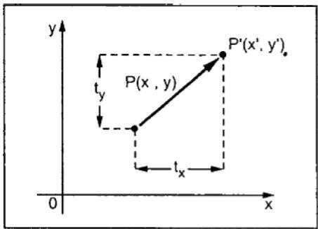
In the figure,
X’=X+tx
Y’=Y+ty
The pair (tx,ty) is called the translation vector or shift vector.

 The equation can be represent by column vector.
P = X
Y

 T = tx
ty
P’=P+T


 = X + tx
Y ty
Scaling
The scaling transformation is done for changing the size of abject.
The dimension of the abject can be compress or expand by using scaling.
The scaling can be achieved by multiplying the original coordinates with the scaling factor to get the desired result.
The scaling factors be Sx and Sy with respt to x and y coordinates.
If the value assigned to the scaling factor S is less than 1 then the size of the abject will compressed.
If the value assigned to the scaling factor S is greater than 1 then the size of the abject will increased.
Following figure shows the scaling process.
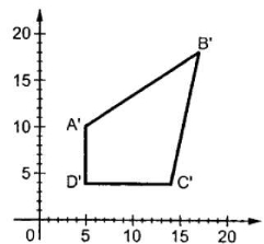
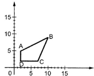
Let assume that the original coordinates are X and Y and the scaling factors are (Sx,Sy).
The mathematics representation of the scaling represented as shown below:
X’=X * Sx
And Y’=Y * Sy
The above equation can be represented in matix form as shown below:


 P= X and S= Sx
Y Sy

 P’=P * S

 = X * Sx
Y Sy
Rotation
The rotation is used for rotating the object at particular angle Ꙫ from its origin.
The following figure shows the point P that is located at angle ф from the horizontal X coordinate with distance r from the origin.
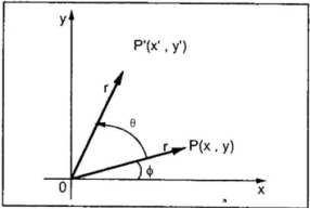
The rotation is achieved by using the following rotation equation:
X’=X * cos Ꙫ - Y * sin Ꙫ
Y’ =X * sin Ꙫ + Y * cos Ꙫ


 In matrix for, the clockwise rotation represented as shown below:
X’ = cos Ꙫ - sin Ꙫ * X
Y’ sin Ꙫ cos Ꙫ Y

 In matrix for, the anti-clockwise rotation represented as shown below:
R= cos Ꙫ sin Ꙫ
-sin Ꙫ cos Ꙫ
The homogeneous coordinates will be represented as:


 X’ = cos Ꙫ - sin Ꙫ 0 * X
Y’ sin Ꙫ cos Ꙫ 0 Y
1 0 0 1 1
Shearing
The shear transformation is used for slanting the shape of the object.
Shearing is also known as skewing.
There are two shear transformations X-shear and Y-shear.
The X-shear shifts the X coordinates and Y-shear shifts the Y coordinates.
In both the cases only one coordinate changes and other preserves.
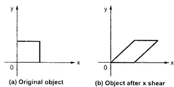
X-shear:
It preserves the Y coordinate and changes made with X coordinate.
Hence only vertical lines of object get tilt on right or left side as shown in below figure:
The transformation matrix for X- shear:
Y’=Y + Shy * X and X’=X
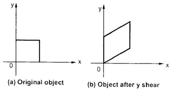
Y-shear:
It preserves the X coordinates and make changes with the Y coordinates.
The horizontal line of the object slopes toward up or down as shown in below figure:
The transformation matrix for X- shear:
X’=X + Shx * Y and Y’=Y
Question-3: Explain following factors of 2D transformation.
Sol:
a) Translation
The translation process is used to move an abject to the different position on the screen.
The translation done by adding translation coordinates (tx,ty) to the original coordinates.
The figure shows the translation process.
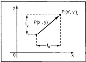
In the figure,
X’=X+tx
Y’=Y+ty
The pair (tx,ty) is called the translation vector or shift vector.

 The equation can be represent by column vector.
P = X

 Y
Y
T = tx
ty


 P’=P+T
= X + tx
Y ty
b) Scaling
The scaling transformation is done for changing the size of abject.
The dimension of the abject can be compress or expand by using scaling.
The scaling can be achieved by multiplying the original coordinates with the scaling factor to get the desired result.
The scaling factors be Sx and Sy with respt to x and y coordinates.
If the value assigned to the scaling factor S is less than 1 then the size of the abject will compressed.
If the value assigned to the scaling factor S is greater than 1 then the size of the abject will increased.
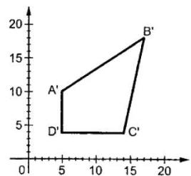 Following figure shows the scaling process.
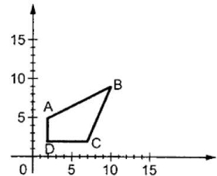
Let assume that the original coordinates are X and Y and the scaling factors are (Sx,Sy).
The mathematics representation of the scaling represented as shown below:
X’=X * Sx
And Y’=Y * Sy


 The above equation can be represented in matix form as shown below:
P= X and S= Sx
Y Sy
P’=P * S


 = X * Sx
Y Sy
Rotation
The rotation is used for rotating the object at particular angle Ꙫ from its origin.
The following figure shows the point P that is located at angle ф from the horizontal X coordinate with distance r from the origin.
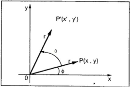
The rotation is achieved by using the following rotation equation:
X’=X * cos Ꙫ - Y * sin Ꙫ
Y’ =X * sin Ꙫ + Y * cos Ꙫ


 In matrix for, the clockwise rotation represented as shown below:
X’ = cos Ꙫ - sin Ꙫ * X
Y’ sin Ꙫ cos Ꙫ Y
In matrix for, the anti-clockwise rotation represented as shown below:

 R= cos Ꙫ sin Ꙫ
-sin Ꙫ cos Ꙫ
The homogeneous coordinates will be represented as :


 X’ = cos Ꙫ - sin Ꙫ 0 * X
Y’ sin Ꙫ cos Ꙫ 0 Y
1 0 0 1 1
Shearing
The shear transformation is used for slanting the shape of the object.
Shearing is also known as skewing.
There are two shear transformations X-shear and Y-shear.
The X-shear shifts the X coordinates and Y-shear shifts the Y coordinates.
In both the cases only one coordinate changes and other preserves.
X-shear:
It preserves the Y coordinate and changes made with X coordinate.
Hence only vertical lines of object get tilt on right or left side as shown in below figure:
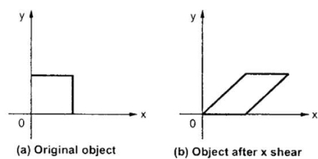
The transformation matrix for X- shear:
Y’=Y + Shy * X and X’=X
Y-shear:
It preserves the X coordinates and make changes with the Y coordinates.
The horizontal line of the object slopes toward up or down as shown in below figure:
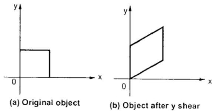
The transformation matrix for X- shear:
X’=X + Shx * Y and Y’=Y
Question-4: Write short note on 3D transformation.
Sol:
The 3D transformations are used to generate the three-dimensional objects in computer graphics.
In 3D transformation the same operations are executed as 2D transformation such as translation, scaling, rotating, shearing etc.
The location of the objects in 3D can be expressed easily as compared to 2D.
The relative viewpoint changes rapidly or sometimes the objects move in relation to each other.
For more graphics the more transformations are carried out repeatedly.
Question-5: Explain rotation about an arbitrary point in 2D transformation.
Sol:
The rotation about an arbitrary point it means the point or a object is located anywhere without origin in plane.
To rotate that point we need to first translate the point on the origin.
Then rotation at the origin processed and again translate the point at the original place.
Steps to be perform the rotation about an arbitrary point:
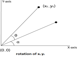
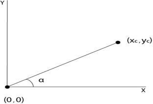
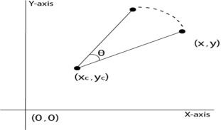
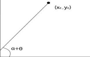
Let the given point (Xc,Yc).
Translate the point (Xc,Yc) at origin (0,0)
Rotation of (X,Y) about the origin takes placed.
Translation at the center takes place again and the object moves to the original position.
Following figure shows the steps of rotation about an arbitrary point.
Question-6: Explain following factors of 3D transformation.
Sol:
Translation
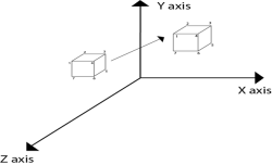
The translation is used for moving object from one position to another position like in 2D.
There are three vectors in 3D to be changed for translation process as x, y, z axis.
In 3D there are also the three translation vectors used.
The translation in x direction represented as tx, in y-direction ty nad in z direction it is represented as tz.
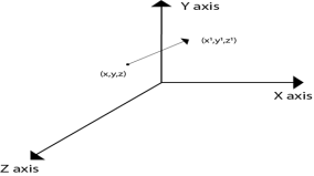
If P (x,y,z) is the point which is going to be translated with the translation vectors(tx,ty,tz) then new vectors will be,
X’=X+tx
Y’=Y+ty
Z’=Z+tz
Following is the matrix for translation:
1 | 0 | 0 | 0 |
0 | 1 | 0 | 0 |
0 | 0 | 1 | 0 |
tx | ty | tz | 1 |
1 | 0 | 0 | Tx |
0 | 1 | 0 | Ty |
0 | 0 | 1 | Tz |
0 | 0 | 0 | 1 |
or
Matrix representation will be,


 X’ 1 0 0 tx X
Y’ = 0 1 0 ty Y
Z’ 0 0 1 tz Z
1 0 0 0 1 1
Following figure shows the translation process in 3D:
Scaling
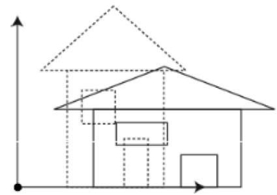
It is used to change the size of object like 2D transformation.
The size can be increased or decreased by using scaling.
If the scaling vectors are same or equal i.e Sx=Sy=Sz then it is known as uniform scaling.
If the scaling vectors are different then it is known as differential scaling.
In 3D there are three scaling factors as Sx, Sy and Sz.
Sx for x direction, Sy for y direction and Sz for z direction.
Marix for scaling is shown as follows:

 Sx 0 0 0
0 Sy 0 0
0 0 Sz 0
0 0 0 1
It is mathematically represented as,

 P’=P * S
[X’ Y’ Z’ 1]= [X Y Z 1] Sx 0 0 0
0 Sy 0 0
0 0 Sz 0
0 0 0 1
= [X.Sx Y.Sy Z.Sz 1]
Steps for scaling the object if the object is located at the fixed place.
Following figure shows the scaling in 3D transformation.
Rotation
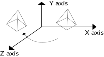
It is used to rotate an object about an angle.
The object can be rotate anticlockwise or clockwise.
This rotation is complex than the 2D rotation.
In this the axis are also important with the angle of rotation.
The axis can be x, y or z.
Following figure shows the rotation about y axis:
Rotation matrix are represented as:
1 | 0 | 0 | 0 |
0 | cosꙪ | -sinꙪ | 0 |
0 | sinꙪ | cosꙪ | 0 |
0 | 0 | 0 | 1 |
Rx(Ꙫ)=
cosꙪ | 0 | sinꙪ | 0 |
0 | 1 | 0 | 0 |
-sinꙪ | 0 | cosꙪ | 0 |
0 | 0 | 0 | 1 |
Ry (Ꙫ)=
Rz (Ꙫ)=
cosꙪ | -sinꙪ | 0 | 0 |
sinꙪ | cosꙪ | 0 | 0 |
0 | 0 | 1 | 0 |
0 | 0 | 0 | 1 |
Shearing
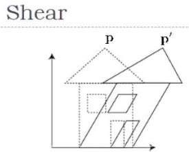
The transformation which is used to slant the object is called as shearing.
In 3D the shearing placed on three axis as X axis, Y axis and Z aixs.
The coordinates are represented in shearing,
X’=X + Shyx * Y+ Shzx * Z
Y’=Y + shxy * X+ Y +Shzy * Z
Z’=Shxz * X + Shyz * Y + Z
Mathematically it is represented as ,
P’=P * Sh
The shearing factors in matrixare represented as,

 Sh= 1 Sh yx Sh zx 0
Sh xy 1 Sh zy 0
Sh xz Sh yz 1 0
0 0 0 1
Following figure shows the shearing in 3D transformation.
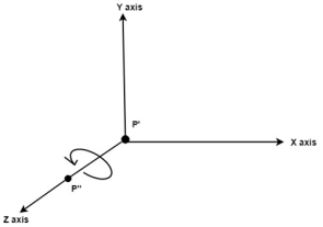
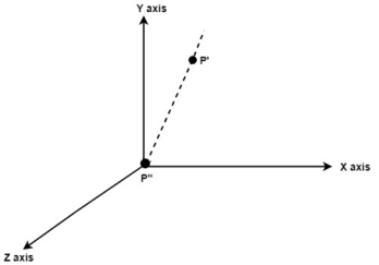
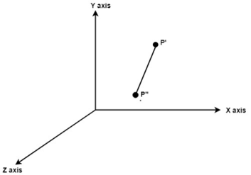
Question-7: Explain rotation about an arbitrary axis in 3D transformation.
Sol:
The rotation about an axis is used when the object is rotated about an axis at that time it is not parallel to axis.
In rotation of object it needs to be parallel to the one of the axis.
Hence the addition transformation is required.
First, it adjusts the alignment of the object and then it translate the object back to the original position.
Following are the steps required to solve the rotation about an arbitrary axis.
Example:
Following figure shows the initial position of P’ and P’’.
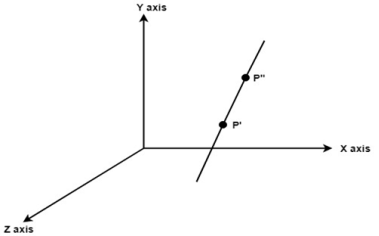
Translate object P’ to origin
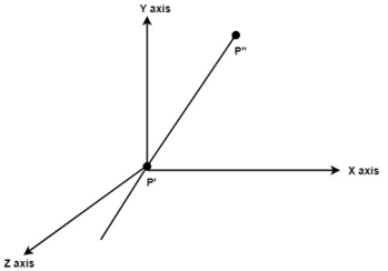
Rotate P’’ to z axis so that it aligns along the z axis
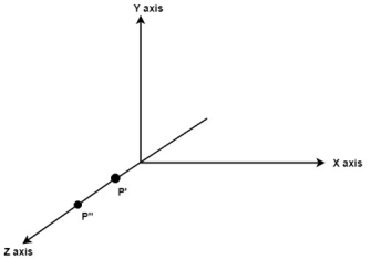
Rotate about around z axis
Rotate axis to the original position
Translate axis to the original position
Question-8: Explain projection in graphics.
Sol:
In 2D, X and Y coordinates are used but in 3D the extra z coordinate is added.
The 3D computer graphics and its applications are applied in computer games, entertainment, etc.
It is also used in scientific visualization.
Parallel Projection
The parallel projection discards the z coordinate.
The parallel line from each vertex on the object are extended until they intersect the view plane.
The direction of the projection will be specified instead of center of projection.
The distance between project plane and the center of the projection is infinite , in parallel projection.
In parallel projection the projected vertices are connected to the original object by line segments.
This projection is good for exact measurement but not so realistic.
There two measure types of projection as follows:
Perspective projection
The distance between center of the projection and project plane is finite in perspective projection.
The distance look realistic in perspective projection.
The size of the object varies inversely with distance.
The parallelism is not maintained as well as the distance and angles are not preserved in perspective projection.
Distance, angles and the lines converge at the center of the projection or projection reference point.
There are three types of points in the perspective projection as given below:
Question-9: Short note on parallel projection.
Sol:
Parallel Projection
The parallel projection discards the z coordinate.
The parallel line from each vertex on the object are extended until they intersect the view plane.
The direction of the projection will be specified instead of center of projection.
The distance between project plane and the center of the projection is infinite , in parallel projection.
In parallel projection the projected vertices are connected to the original object by line segments.
This projection is good for exact measurement but not so realistic.
There two measure types of projection as follows:
3. Oblique projection
4. Orthographic projection
Oblique Parallel Projection
The projection of the plane and the direction of the projection is not normal in oblique projection.
The object can be view better in oblique projection than orthographic projection.
There are two types in oblique projection as follows:
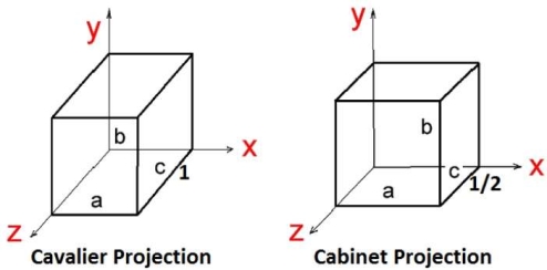
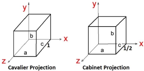
Cavalier Projection:
The cavalier makes the angle 45 to the projection plane.
In cavalier the projection line is perpendicular to the view plane with same length as the line itself.
The foreshortening factors for all three principal directions are equal.
Cabinet Projection:
The cabinet makes the angle 63.4 to the projection plane.
In cabinet the projection line is perpendicular to the view plane surface with 1/2 length as the line itself.
Both the projections are as follows.
Question-10: Short note on oblique projection.
Sol:
The projection of the plane and the direction of the projection is not normal in oblique projection.
The object can be view better in oblique projection than orthographic projection.
There are two types in oblique projection as follows:
Cavalier Projection:
The cavalier makes the angle 45 to the projection plane.
In cavalier the projection line is perpendicular to the view plane with same length as the line itself.
The foreshortening factors for all three principal directions are equal.
Cabinet Projection:
The cabinet makes the angle 63.4 to the projection plane.
In cabinet the projection line is perpendicular to the view plane surface with 1/2 length as the line itself.
Both the projections are as follows.
Question-11: Explain orthographic projection.
Sol:
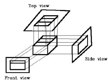
In orthographic projection the direction of the projection is normal to the projection of the plane.
There are three types of the orthographic projections:
Following figure shows the orthographic projection.
Isometric Projection:
The object that shows the more than one side of the object in orthographic projection then it is known as axonometric orthographic projections.
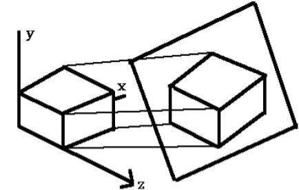
The isometric projection is the most common axonometric projection.
The projection plane intersects each coordinate axis in the model coordinate system at an equal distance.
The angles of projection are not preserved but parallelism of projections are preserved.
Following figure shows the isometric projection:
Diameter Projection:
In diameter projection, two of the three axes of space appears foreshortened.
The direction of viewing is equally foreshortened.
Based on angle of viewing the attendant scale and angles of presentation are determined.
The scale of the third direction is determined separately.
The dimensional approximation is common in diametric projection.
Trimetric Projection:
In diameter projection, all three axes of space appears foreshortened.
The direction of viewing is unequally foreshortened.
Based on angle of viewing the attendant scale of three axes and angles of presentation are determined.
The dimensional approximation is common in trimetric projection.
The trimetric perspective is used in trimetric drawings.
Question-12: Explain perspective projection.
Sol:
The distance between center of the projection and project plane is finite in perspective projection.
The distance look realistic in perspective projection.
The size of the object varies inversely with distance.
The parallelism is not maintained as well as the distance and angles are not preserved in perspective projection.
Distance, angles and the lines converge at the center of the projection or projection reference point.
There are three types of points in the perspective projection as given below: