Unit - 4
Introduction to State Space Analysis
Q1) Obtatin the state space representation for the given electrical system.
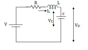
A1) The state model is given as
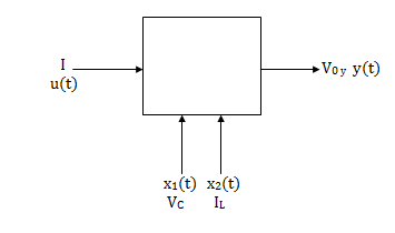
The state model shows that there are two energy storing elements L, C. As we already know that Number of state variables is equal to the number of energy storing elements.Hence we have two state variables[x1(t) and x2(t)]. We have one output V0(taken across capacitor) and input u(t).
The output equation is then given as
Y(t)=CX(t)+DU(t)
V0=Vc= x1(t) ….(a)
Hence output equation becomes
V0= x1(t)
y(t)=[1 0] +[0]u(t)
So, C=[1 0] D=[0]
Now writing the state equation
 =Ax(t)+Bu(t)
For that applying KVL in the above circuit
V=ILR+L +Vc
+Vc
State Equation is  =Ax(t)+Bu(t)
 =
=
x1(t)=Vc
 =
=
IL=C
 =
=
 =
= =
=
 =(1/C) x2(t) ……….(b)
 =
= =
=
VL=L
 =
= =VL/L
=VL/L
From KVL
L =VL=V-ILR-VC
 =
= =
=
 =
= …………….(c)
From equation (b) and (c)
 = [0 1/c]
 + [0 0]u(t)
 =[-1/L -R/L]
 + [1/L 0]
Now writing the state equation
 =Ax(t)+Bu(t)
 =
= +
+ 
Hence A= B=
B= 
Q2) Obtatin the state space representation for the given electircal system.
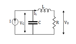
A2) The state model shows that there are two energy storing elements L, C. As we already know that Number of state variables is equal to the number of energy storing elements.Hence we have two state variables[x1(t) and x2(t)]. We have one output V0(taken across capacitor) and input u(t).
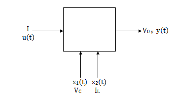
Here output is V0. But from above electrical circuit V0=ILR
V0=x2(t)R
y(t)= V0= [0 R]  + [0] u(t)
The output equation is given as
Y(t)=CX(t)+DU(t)
C=[0 R] D=[0]
Now finding state equation,we apply KCL in the given electrical circuit
I=IC+IL
 =
=
But I-IL=IC
 =
=
 =
=
 =
=
 =
= x2(t)+
 ……..(a)
 =[0 1/C]
 + [1/C 0]
 …….(b)
 =
= =
=
Applying KVL in the given electrical circuit we get
VC=VL+ILR
VC-ILR=VL=L

 =
=
 =[1/L -R/L]
  + [0] u(t) ………….(c)
From equation (b) and (c) we have
Now writing the state equation
 =Ax(t)+Bu(t)
 =
= +
+ 
Hence A= B=
B= 
Note: We should always take voltage across the inductor L, and current through capacitor C.
Q3) Write the state equation for the mechanical system shown below.
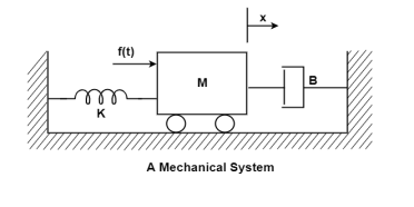
A3) The free body diagram is

The position and velocity are state variables hence,
x1(t)=x(t)
x2(t)= 
 =
= =x2(t)
 =
=
The system equation will be

 =
=
 =
=
 =
=
The state equations are
 = x2(t)
 =
=
 =
= +
+ f(t)
f(t)
Q4) The closed loop transfer function is given as T(s)=  . Calculate the state model?
A4) The transfer function can be simplified using partial fraction method as
 =
=
S+2=As+10A+Bs+5B
Equating coefficients of s from both sides
A+B=1
Equating coefficients of s0 from both sides
10A+5B=2
Solving above equations we get
A=-3/5
B=8/5
The transfer function will be
T(s)=
=- +
+
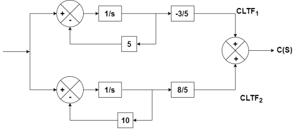
Number of poles= Number of energy storing elements
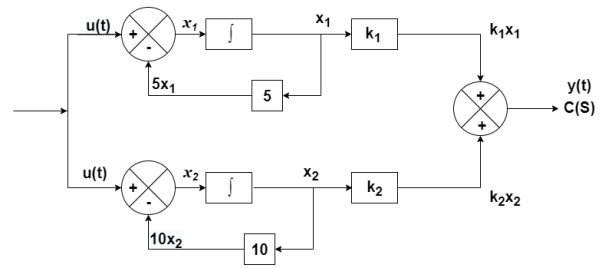
The output equation is given as
y(t)=k1x1(t)+k2x2(t)
y(t)= [k1 k2] + [0] [u(t)]
y(t)= [-3/5 8/5] + [0] [u(t)]
C=[-3/5 8/5]
D=0
From the above block diagram
 =u(t)-5 x1
 =-5x1+u(t)
 =-10x2+u
Therefore, the state equation is given as
 =
= +
+
A=
B=
Q5) The closed loop transfer function is given as T(s)=  . Calculate the state model.
A5) The transfer function can be simplified using partial fraction method as
 =
= +
+ 
s+7=A[s2+7s+12] +B[s2+6s+8] +C[s2+5s+6]
Equating coefficients of s2 from both sides
A+B+C=0
Equating coefficients of s from both sides
7A+6B+5C=1
Equating coefficients of s0 from both sides
12A+8B+6C=7
Solving above equations and finding values of A, B and C
A=5/2
B=-4
C=3/2
The transfer function will be
T(s)= +
+ 
= +
+ 

The output equation will be
y=k1x1+k2x2+k3x3
y=[k1 k2 k3] [5/2 -4 3/2]
C=[5/2 -4 3/2]
D=[0]
The state equation is given as
 =u(t)-2x1
 =-2x1+u(t)
 =-3x2+u
 = -4x3+u
Therefore
 =
= +
+ [u]
[u]
A=
B=
Q6) The closed loop transfer function is T(s)=  . Find the state equation.
A6) Here the number of poles = number of zeros
T(s)=
=
=
=2+ 
=2+
Solving above by partial fraction method
88= As+2A+Bs+3B
A=-B
2A+3B=88
A=-88
B=88
The transfer function becomes
T(s)= 2-
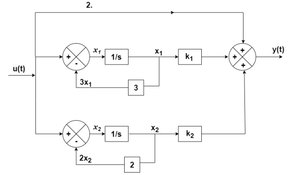

The output equation will be
y(t)=2U+k1x1+k2x2
y=[-88 88] +[2]u
+[2]u
The output equation will be
 =u(t)-3 x1
 =-3x1+u(t)
 =-2x2+u(t)
Therefore, the state equation is given as
 =
= +
+
A=
B=
Q7) The CLTF T(s)= . Find the state equation.
A7) T(s)=
=
P1=2/s
P2=-8/s2
L1=-10/s
L2=-100/s2

The state equation will be
 =x2
=x2
 =-10x2-100x1+u
 =
= +
+
Q8) Find the state equation from the given differential equation.

A8) Let y=x1
 =
= =x2
=x2
 =
= =x3
=x3
 =
=
The above differential equation than becomes
 +6
+6 +11 x2+6 x1=u
 (t) =u-6
 (t)-11 x2-6 x1
Hence the state equation will be
 =
=  +
+ [u]
[u]
Q9) For the given data below compute the transfer function of the system.
A= B=
B= C=[1 0] and D=[0]
A9) The state equation will be
 =
= +
+
 =x1
=x1
 =-6x1-5x2
Equation (14) in section 4.1
 = C{[SI-A]-1B} + D
=C{ -
- }-1B+D
=C B+D
B+D
=[1 0] 
 + 0
+ 0
= +0
+0
 =
=
Q10) Obtain the state space representation of following mechanical system.

A10) The position and velocity state variables will be
x1=y1
x2=
x3=y2
x4=
The difference equation will be
M1 +B1
+B1 +K1y1+B2(
 -
- +K2(y1-y2)=0
M2 + K2(y2-y1) + B2(
 -
- )=u
)=u
Writing above equations in the form of state variables
M2 =u-K2(y2-y1) +-B2(
 -
- )
)
M1 =- B1
=- B1 -K1y1-B2(
 -
- -K2(y1-y2)
 = -(
= -( +
+ )x1- (
 ) x2+(
 )x3+
)x3+ x4
x4
 =
=  x1+
x1+ x2-
x2- x3-
x3- x4+
x4+
Now writing all the state equations
 =x2
=x2
 = -(
= -( +
+ )x1- (
 ) x2+(
 )x3+
)x3+ x4
x4
 = x4
= x4
 =
=  x1+
x1+ x2-
x2- x3-
x3- x4+
x4+
The matrix form for above equations is given below
 =
=  +
+ v(t)
v(t)
Q11) Derive the State model of armature control DC motor.
A11) In armature-controlled motors the time constant is small and hence response is fast. The efficiency is better than field cannot. The transfer function is calculated below.

Fig Armature controlled d.c servomotor.
Applying kVL in armature circuit
V = Raia+ Ldia/dt +E-----(21)
Where
V= applied voltage
Ra = armature resistance
La = Armature inductance
Ia= Armature current
If= field current
E= Induced emf in armature
T= Torque developed by motor
But Eb= Kb w
Eb= kbdø/dt --------(22)
W =angular velocity
Kb= back emf
T= k ia-----(23)
The equation for torque will be
T= Jd2ø/dt2+Bdø/dt --------(24)
- In mechanical systems the energy is stored in mass as the function of position and velocity. Therefore, the state variables are
 . The current ia is another state variable.
Let x1=
x2= and x3=ia
 =x2
=x2
Eb= kbdø/dt
T= Jd2ø/dt2+Bdø/dt
T= k ia
Jd2ø/dt2+Bdø/dt= k ia
V(t)-Eb=Raia+ Ldia/dt
V(t)- kbdø/dt = Raia+ Ldia/dt
From above equations we can write
J +B x2=k x3
V(t)- kb x2=Ra x3+L
Simplifying above two equations we get
 =
=
 =
=
The matrix is given as
 =
=  +
+ v(t)
v(t)