Unit -I
Unit -I
Introduction to PLC
Q1) What is the Role of automation in Industries?
A1) In the scope of industrialization, automation is a step beyond mechanization. Whereas mechanization provided human operators with machinery to assist them with the muscular requirements of work, automation greatly reduces the need for human sensory and mental requirements as well. Processes and systems can also be automated. Automation plays an increasingly important role in the global economy and in daily experience. Engineers strive to combine automated devices with mathematical and organizational tools to create complex systems for a rapidly expanding range of applications and human activities. Many roles for humans in industrial processes presently lie beyond the scope of automation. Human-level pattern recognition, language recognition, and language production ability are well beyond the capabilities of modern mechanical and computer systems. Automation is the conversion of a work process, a procedure, or equipment to automatic rather than human operation or control. Automation does not simply transfer human functions to machines, but involves a deep reorganization of the work process, during which both the human and the machine functions are redefined. Early automation relied on mechanical and electromechanical control devices; during the last 40 years, however, the computer gradually became the leading vehicle of automation. Modern automation is usually associated with computerization.
Q2) What are the Benefits of automation? Explain each in brief.
A2)
1. Lower operating costs
It can perform the work of three to five people, depending on the task. In addition to savings on the cost of labor, energy savings can also be significant due to lower heating requirements in automated operations. Robots streamline processes and increase part accuracy, which means minimal material waste for your operation.
2. Improved worker safety
Automated cells remove workers from dangerous tasks. Your employees will thank you for safeguarding them against the hazards of a factory environment.
3. Reduced factory lead times
Automation can keep your process in-house, improve process control and significantly reduce lead times compared to outsourcing or going overseas.
4. Faster
Automation solutions are based on your unique needs and goals and pay for themselves quickly due to lower operating costs, reduced lead times, increased output and more.
5. Ability to be more competitive
Automated cells allow you to decrease cycle times and cost-per-piece while improving quality. This allows you to better compete on a global scale. Additionally, the flexibility of robots enables you to retool a cell to exceed the capabilities of your competition.
6. Increased production output
A robot has the ability to work at a constant speed, unattended, 24/7. That means you’ve got the potential to produce more. New products can be more quickly introduced into the production process and new product programming can be done offline with no disruption to existing processes.
7. Consistent and improved part production and quality
Automated cells typically perform the manufacturing process with less variability than human workers. This results in greater control and consistency of product quality.
8. Smaller environmental footprint
By streamlining equipment and processes, reducing scrap and using less space, automation uses less energy. Reducing your environmental footprint can save real money.
9. Better planning
Consistent production by robots allows a shop to reliably predict timing and costs. That predictability permits a tighter margin on most any project.
10. Optimal utilization of floor space
Robots are designed on compact bases to fit in confined spaces. In addition to being mounted on the floor, robots can be mounted on walls, ceilings, rail tracks and shelves. They can perform tasks in confined spaces, saving you valuable floor space.
Q3) Why PLC is necessary?
A3)
- PLC is used in the fully automated industries or plants or process, the actual processes handled and controlled by the controllers which are nothing but the programming logic controllers that means PLC plays a very important role in automation section.
2. PLCs constantly monitor the state of the systems through input devices and generate the control actions according to the logic given in the user program.
3. It is a heart of control systems, PLC monitors the state of the system through field input devices, feedback signals and based on the feedback signal PLC determine the type of action to be carried out at field output devices.
4. PLC provides easy and economic solution for many automation tasks like
i. Operates control and monitoring.
Ii. Co-ordination and communication.
Iii. PID computing and control.
Iv. Logic / sequence control
Q4) Explain PLC (Programmable Logic Controller).
A4)
1. A Programmable Logic controller (PLC) is a solid state/ computerized industrial controlled performs discrete or sequential logic in a factory environment.
2. It was originally developed to replace mechanical relay, timers, and counters.
3. PLCs are used successfully to execute complicated control operations in a plant.
4. A sequence of instructions is program by the user to the PLC memory and when the program is executed, the controller operates a system to the correct operating specifications.
5. The first commercial PLC was introduced in the late sixties when microprocessor word not available.
6. In the late 1970's with the advent of microprocessors, the role of PLCs was greatly enhanced.
7. Capability such as intelligent operator interface,arithmetic data manipulation and computer communication added a new dimension to PLC applications.
8. Hardware enhancement included larger memory capacity, analogue input/ output and has specific data communication between Programmable Logic controllers. PLC technology is being continuously upgraded even today.
9. Today a PLC is used as stand-alone control or as part of a complex computer integrated manufacturing (CIM) system.
10. A PLC may also provide an interface between machine and robots for a machine and color graphics which are known as human machine interface (HMI). A PLC can now be found in every type of industry imaginable.
11. PLC is as important to the world of industrial automation as the computer in the business world.
Definition of PLC
A Programmable Logic controller is currently defined by “National Electrical Manufacturing Association (NEMA)”as a “Digital Electronic Device that uses a Programmable memory to store instructions and to implement specific functions such as logic, sequence, timing, count and arithmetic operations to control machine and processes.”
Q5) What is the history of PLC?
A5) Its advent of solid-state technology revolution took place in the areas of industrial control and communication. Many manufacturers attempted to develop faster and more efficient control techniques using available modern technologies.
1959:- First solid state control system PDQ designed by Allen Bradley to replace the relay came into use, but it was not reprogrammable.
1968:- PLCs were designed by Bedford associates later known as Modicon for General Motors Corporation. They replaced costly release used in control circuits of their assembly lines during modernization of control systems.
1969:- the first PLC was manufactured by Modiconfor the automotive industry. They were used by General Motors as electronic equivalent of relay-based control circuit and were named Hard Hat-089.
Allen Bradley develop the PLC for General Motors. However, it was not accepted by them.
1970:- more modifications were made by Modicon and many models were made with many specialized characteristics. Allen Bradley designed the PMC program controller.
1971:- First application of PLCs is outside of the automotive industry.
1972:- Modicon introduces fully Programmable PLC's using ladder logic and solid-state input with microcomputer processor.
1973:- Introduction of smart PLC for arithmetic operations printer control data move Matrix operation CRT interface etc.
1975:- Introduction of analogue PID (proportional integral derivative) control which made the assessing of thermocouples pressure sensors etcetera possible after Bradley introduced PLC to having advanced control and minicomputer interface facilities.
1976:- First use of PLC's in hierarchical configuration as part of an integrated manufacturing system.
1977:- Introduction of very small PLC's based on microprocessor technology.
1978:- PLC's gain wide acceptance.
1979:- Integration of plant operation through a PLC communication system. Allen Bradley introduce PLC-2/20 provided with advanced control with extensive fault diagnostics, analogy module, signal interface and position controls.
1980:- Introduction of intelligent input and output module is to provide high speed accuracy control in position applications.
1981:- Data highways enable users to interconnect many PLC at distance of up to 4500 more 16 – bit PLC's become available. Color graphic CRT’s are available from several suppliers.
Allen Bradley introduces the mini PLC 2/15 and mid-size PLC 2/30, which arrowed mathematical calculations and facilities of counter timer, sequencer, word file, block transfer, data highway. Compact ability and online and offline programming.
1982:- Larger PLC’s with up to 8192 input become available.
1983:- Third-party peripherals including graphics operators interfaces smart input networks panel displays and documentation packages become available from many sources.
1984:- Allen Bradley introduces PLC 4 which was a small unit providing 20 input and 12 outputs. A number of such small PLC could be interconnected to control a total plant.
1990's:- Structural change brought forth by the distribution of input and output. The input output and peripheral devices were connected to the central controller by thin 2 to 4 wire cables.
2000 & beyond:- Nowadays digital communication has spared the way for industrial control in which PLC are major contributors.
Q6) What are the types of PLC?
A6)
1. Fixed:
This type of PLC is most commonly called the Fixed I/O PLC.
“Fixed I/O” actually stands for Fixed “Input/output”. When you buy Compact PLCs, you will notice that the input section and the output sections of the PLC are integrated into the microcontroller itself.
This means that every type of output or input is fixed and is determined by the manufacturer.
Furthermore, the number of inputs and outputs may not be expanded in this type of PLC.
2. Modular:
The modular PLC is a type that allows multiple expansions of the PLC system through the use of modules, hence the term “modular”.
Modules give the programmable logic controller additional features like increased number of I/O units, and they are usually easier to use because each component is independent of each other.
The power supply, communications module, Input/output module are all separate to the actual microcontroller so you have to manually connect them to each other to create your PLC control system.
A type of modular PLC is the rack-mounted or rack mount PLC. In a rack mount PLC, the communications module of the PLC resides in the rack itself, so all connections are centralized.
Q7) Explain Overall PLC system with diagram.
A7) Amplified block diagram of PLC is shown in figure it is seen that a PLC has three basic sections namely
1. Input/output section
2. Processor section
3. Program loader monitor section
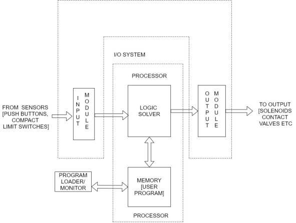
_Input section converters convert the field signals to logic level signals that the PLC is processor can read directory.
_The processor section reads these inputs processes the signals executing the program and prepares the output signals.
_The output section converts the logic level output signals coming from the processor section into high-level signals and releases signals for various fields devices.
_The program loader is used to enter the user’s program into the memory or change it and to monitor the execution of the program.
Input output section
The input output section stablished the interfacing between the real world outside the PLC and the digital arena inside the PLC the signals from machines or instruments of a system are received through the input section by a PLC, after processing the output signals are transmitted to the machines are the instruments for the desired control action through the output section.
Task of the input output section classified as
a) Conditioning
b) Isolation
c) Termination
d) Indication
The field signal available is 220 volt or 440 volt since a PLC can only support voltage of 0-10V, the field signal has to be condition before it is applied to PLC.
To protect a PLC from any incoming surges from the field isolating devices such as a T/F or an up to isolators are used. The input output module provides a proper terminal. It indicates the status of the input output terminal, when the voltage is the status indicator is off.
Processor section
A block diagram of the processor section of a PLC shown in figure
This section consists of four major elements
- Power supply
- Memory
- CPU
- Input output interface
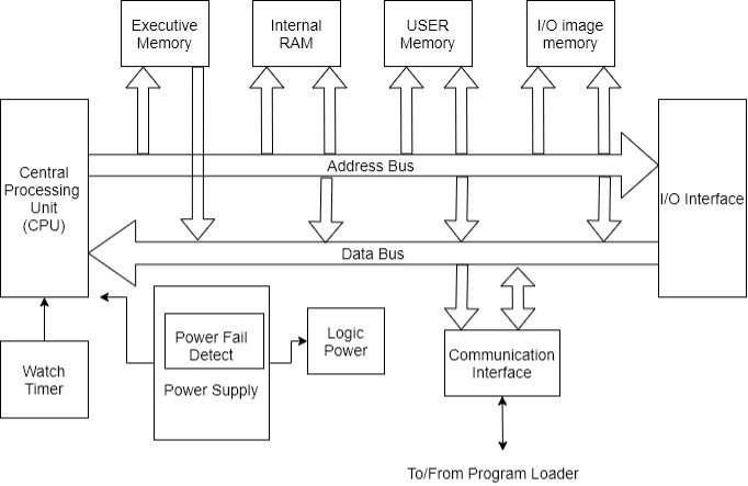
Detailed block diagram of processor section at PLC
Q8) Explain Power supply.
A8) The basic function of the power supply is supply conditioned power to the components of PLC.
The power supply is one of the most critical components of the PLC for two reasons:
a) It is typically known reluctant. Hence, failure of the PLC power supply can cause the entire control system to fail.
b) It contains High voltage components. Hens and insulation failure can be serious potential for injury or fire.
The following guidelines should be followed when choosing the power supply of a PLC:
- The power supply should be packed properly so that the heat generated by the power supply can be dissipated in order to prevent overheating this increases reliability.
- The power supply should be tested for temperature and electrical insulation by a proper certification agency.
- The power supply should meet the at least one reputable standard for rise immunity. It should also be capable of withstanding line voltage variation such as chop outs, broon outs and surges, which are common industrial faults.
- Suitable redundancy will increase reliability.
Q9) Explain types of Memory in PLC.
A9) Two types of memory in PLC
i. Volatile memory
Ii. Nonvolatile memory
Nonvolatile memory is generally used for storing users’ program so that they are preserved during power cuts.
Different types of memory that are generally used in PLC are as follows.
Battery backed up CMOS RAM:-
This is probably the most widely used type of memory all through most Ram’s are inherently volatile the CMOS variety consumers such a small amount of power that a small battery will retain the memory during power loss. The battery used vary from short life primary cells which require periodic replacement after 6 months to air to long life cells which may last upto 10 years.
EPROM Memory:-
Electrical Programmable read-only memory is programmed using electrical passes and can only be raised by exposing the circuit to UV light also caused UV EPROM.
EEPROM memory:-
This memory is similar to EPROM memory but it can also be raised using electrical pulses. In some PLC EEPROM is the only type of memory used. This allows for flexibility of reprogram.
As shown in figure the total memory area is subdivided into four sections namely executive memory section internal RAM, user memory and image memory.
The executive memory holds the executive software and user memory is meant for user program storage the functional explanation of input output image section has been given below.
Functions of input output image memory
- Process image input: - At the beginning of the scan cycle the operating system reads the inputs from the process and record the values in this area the program can use these values in its cycling processing.
- Process image output: - during the scan cycle the program calculates output values and places them in this area. At the end of the scan cycle operating systems reads the calculated output values from this area and send them to the process outputs.
- Bit memory: - this area provides storage for entrance results calculated in the program.
- Timers and counters:- timers are function elements of ladder programming this area provides storage of timer cells. In this area clock timing assesses time cell to update them by decrementing the time value. Counter are functions element of ladder programming this area provides storage for counters. Counter instruction them.
Q10) What is CPU? Explain.
A10)
- The CPU is the heart of the PLC system.
- The CPU used may be smaller or Larger one depending on the size of the process to be controlled.
- It is important to size the system CPU according to the internal memory needed to run the process.
- Controlling the small operation only a small PLC unit with limited memory controlling a larger system would require larger unit with more memory and functions.
- Some CPU's can have additional memory easily added at a later date others cannot be added to or expanded.
- Advanced planning with the manufacturer is required to match present and future needs with the size of the system being purchased.
- Many CPU contains backup batteries that keep the users process control ladder program in storage in the event of the plant power failure.
- The basic operating system is stored permanently in the CPU in read only memory and is not lost when input power is lost.
- However, the user process control ladder diagram being in random access memory is not stored permanently.
- The CPU who all have operational switches some of which require key to prevent unauthorized personal from running a turned off process.
- The key types which also can prevent unauthorizedactoration to the operating system program.
- The switch position varies from manufacturer and manufacturer but are similar typical positions are
a) Off: - system cannot be run or programmed.
b) Run: - allows the system to run but no program attraction can be made.
c) Disable: - Turns all output of or sets them to the in operable state.
d) Monitor: - turns on screen that display operating information.
e) Run/program: - system can run and program modification can be made to it while it is running. This mode must be used with caution. In this mode the program can be completely erase but can only be modified. To delete an entire program the key must be in disable position.
f) Off/program or program: - system cannot run but can be programmed or reprogrammed
Programmer (monitor)
The programmer is connected to the CPU by a cable. After the CPU has been programmed the team is no longer required for CPU and process operation and can be disconnected and removed. Therefore, you may be need only one PM for a number of operational CPU’s. The PM may be moved about in the plant as needed the same pm can be used in the office or lab to pretest program.
Q11) Explain PLC Input and output modules (along with Interfaces).
A11) Input output module are available as either input only output only or a combination of inputs and outputs.
Discrete input module
The discrete input module is the most common input interface used with Programmable controllers discrete input signals from field devices can be either AC or DC.
Discrete AC input module
A 120 volt AC input will accept signals between so and 135 volt AC common inputs include limit switches, proximity, photoelectric switches, selector switches, relay contacts and contact closure from other equipment’s figure illustrates wiring for atypical 120 volt AC input module. The left module has its common connected internally. All inputs will have the same voltage the right module is a 120- or 230-volt AC input module. The module has to separate common which allows the user to write two different input levels.
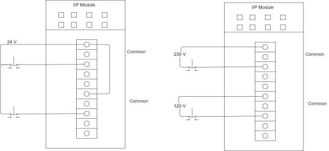
The input module is considered the load for the field input device. The module's job is to convert the 120-volt A.C., high voltage signal to the 5-voltD.C level. With which the PLC can work. The module job is to verify the input as a valid signal,isolate the high voltage field device signal from the lower voltage CPU signal and send the appropriate or off signal to the CPU for placement in the input status file. Does circuitry contain in an input module is composed of three parts:-
Power file conversion, isolation and logic as shown in figure.

Alternating current enters the input module(sections) and then flows to the power conversion section.
Power conversion
The power conversion section usually consists of resistors and a bridge rectifier. The bridge rectifier converts the incoming DC signal to a pulsating DC level (section 3). The DC level is passes through filters and other logic (sections) to deliver a clean de bounced DC input signal (sections). The filtered DC signal goes on to the threshold detector (section 6).
Threshold detection
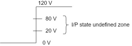
Search for detection circuitry detects if the incoming signal has reached or exceeds pre-determined value for a pre-determined time and weather it should be classified as a valid ON or OFF signal, module specification can thus the valid ON/OFF state vtg range. Atypical valid OFF state is between 0 and 20 or 30V A.C depending upon module manufacture. A valid ON state will be between 80 and 132 2-volt AC. Again depending on the manufacturer, the signal area between the output voltage limit for a valid off state (20 volt) and the minimum voltage for a valid ON state (80 volt) is called the undefined or input state not guaranteed. Signals falling within this undefined area may be ON or OFF making them unstable and reliable.
Isolation
The isolation section of the input circuit is usually made up of and optical isolator for op to coupler. In a 120-volt AC input module isolation separates the high voltage, 120-volt AC input signal from the CPU's low voltage control logic. The low voltage control logic signals associated with the CPU will run from 5 to 18-volt dc, depending on the module manufacturer and the type of logic employed.
Isolation is accomplished by the input signal energizing light emitting diode (LED) which transmits a signal of light energy to receiver in the form of photoconductive diode. Simply put the LED convert the electrical signal to an optical signal. The receiver usually a photo transmitter, convert optical signal back to an electrical signal. There is no actual physical or electrical coupling between the sending LED, its associated circuits and the optical receiver and its 100-voltage associated logic circuitry. The signal is transferred by light from the LED. Figure shows a simplified optical isolator.
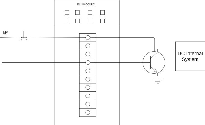
The logic sections
DC signals from the opto-coupler are used by the logic section (section 8) to Pan the input signal to the module's input address LED (section 9) and the CPU (section 10)and then onto the input status file via wired on the rack's black plane call the data bus.
The two types of input devices
1) There are two types of input devices commonly interfaced to an input module.
2) One type includes the mechanical limit switch, toggle switch, push button and contacts from an electromechanical relay.
3) Every one of these devices has something in common circuit continuity is either made or broken by physically opening a set of contacts.
4) When open these contacts have a physical air thus there is infinite resistance, resulting in zero current flow through the physically open contacts.
5) Since these are mechanical contacts there no electrical power required to make the device operate.
6) The second type, the solid-state proximity device, On the other hand is an electronic device which means that it needs power to operate.
7) A small all amount of current must continuously flow through the device even in the OFF state to keep the internal electronics working so that the switch will be able to sense the presence of an object.
8) Figure shows the two-wire connection for a solid-state proximity sensor.
9) Notice that there is only a single part for power flow not only to provide the ON or OFF signal the load, but also to provide that small amount of current to operate the internal electronics.
10) The current flowing through the sensor to operate internal electronics is called its Leakage current.
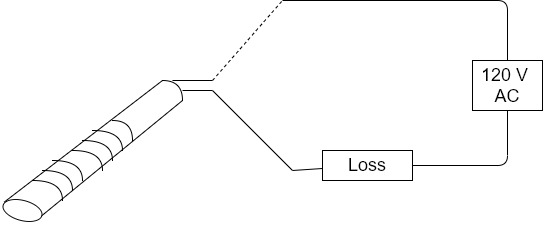
11) Excessive leakage current could possibly cause on input module's input point to turn on in error is the module's maximum off state current is exceeds.
12) Figure shoes 2 inputs going into an input module. Input A is a mechanical limit switch, when the limit switch is open, there exist a physically open circuit, thus, there is zero current flow into input point 0.
13) Input 6 is an inductive proximity switch. Although the switch is in the off or de-energized state and the schematic symbol shows and open circuit must be current flow through the electronics to keep the sensor operating so that it will be able to switch from open to closed when a target comes into range.
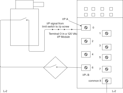
14) Leakage current for a 2-wire sensor is typically less than 2 MA[usually around 1.7 MA].
15) Some larger high-power sensors can have leakage current as high as 3.5 MA or more.
16) Most sensor manufacturer has a standardized leakage current value of less than 2 MA so that we can interface to most PLC's.
17) A typical AC input module will accept leakage current of less than 2 MA and still read the signal as the valid OFF.
DC input module operation
Except for the bridge rectifier circuit, the DC i/p module is very similar to the AC input module. Since the input signal is already. DC, no bridge rectifier is necessary. Resistors are used to drop the incoming voltage before passing the signal onto the remaining electronics. Figure shows A simplified block diagram for DC i/p module.

Discrete output modules
1) Much like discrete i/p discrete o/p are the most commonly used type.
2) Discrete o/p module simply acts as switches to control o/p field devices. They fall into two classification- solid state o/p switching and relay output switching.
3) Discrete o/p module receives their operating power from the PLC's power supply.
4) Usually the user must provide the power that the module o/p switches to control the field devices.
5) Figure shows basic field wiring for discrete 120 V AC o/p modules.
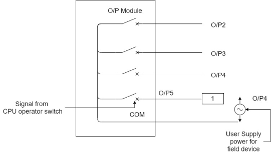
6) Discrete output module comes in various signal levels and specifications.

Solid state output module switching
1. A typical AC o/p module contains circuitry as shown in block diagram.
2. A single AC o/p point consists of a latching circuit for the low voltage [12-18V de] logic signal sent by the CPU from the o/p status table.
3. The ON /OFF signal represents the logical value of o/p.
4. If the o/p status table bit is 1 the own signal will be latched into the logic circuitry block.
5. This ON signal will be passes through the optical isolation circuitry to the block containing the switching hardware.
6. In a solid-state AC o/p module, a triac is used to switch the AC high voltage and current controlling the ON or OFF state of the field hardware device.
7. A traces a solid-state device used to switch AC.
8. The filter block will contain protective devices such as a metal oxide varistor (MOV)
9. The MOV is used to limit peak voltage across the AC switching hardware to a safe value.
10. The o/p points LED alerts the operator that the o/p has been directed by the CPU to turn ON
11. The tube may also be included on the o/p line to protect the easy switching device from drawing too much current.
Relay output module
1. Relay o/p modulus r are also known as Contact o/p or dry contact o/p.
2. Even through relay o/p module are used to switch AC or DC loads. Usually relay o/p are used to switch small currents at low voltages to multiplex analogue signals and to interface control signals to variable speed drives.
3. Relay o/p modules use actual mechanical relay one for each o/p status file.
4. Figure shows one point of relay o/p module. Notice that common goes to the other relay in the group.
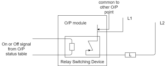
5. Relay o/p what DU user available in three variations depending on the manufacturer.
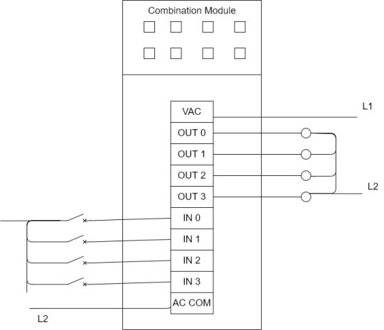
6. Most manufacturers offer combination i/p and relay o/p module.
7. Combination relay module usually come with two, four or six 120 V AC i/p and two, four or six relay o/p.
8. Following figure shows 4-point 120 V AC i/p and a 4-point relay o/p combination module. Notice that relay o/p accepts AC or DC signals.
Q12) Write Specifications about CPU and Digital Input Module.
A12)
1. Central processing Unit
a. System characteristics: Should be programmed with STEP 7 or higher, Automatic routing via PROFINET / Profibus, independent of network Data block routing via PROFINET / Profibus Integrated Web server functionality Integrated communication services (TCP/IP, UDP, ISO on TCP, SNMP, NTP, PROFINET CBA/IO) Isochronous operation on the bus system
b. Integrated work memory: 384 Kbyte
c. Integrated load memory: 8 MByte
d. No. Of timers: 256
e. No. Of counters: 256
f. No. Of bit memories: 2048 Byte
g. Processing times for bit-operations, min.: 0,05 µs for word operations: 0,09 µs for arithmetic operations: 0,12 µs for floating point arithmetic: 0,45 µs
h. Interfaces MPI (RS485), PROFIBUS (RS485), PROFINET (RJ 45-Ethernet), Integrated PROFINET Switch
i. Integrated functions Real-time clock, Buffer time 6 weeks, Password protection
j. Supply voltage Rated value: 24V DC
2. Digital Input Module
- Supply voltage 24 V DC Yes
Permissible range, lower limit (DC) 20.4 V
Permissible range, upper limit (DC) 28.8 V
2. Number of digital inputs 16
3. Input voltage Rated value, DC for signal "0" for signal "1" 24V -30 to +5 V 13 to
30V.
4. Input delay for standard inputs Programmable 0.1/.5/3/15/20 ms 5 Status display Sensor supplies Green LED per channel Green LED per group 3 Galvanic isolation between channels Groups of 16 4 Opto isolation between channels and backplane Opto isolation.
5. Permissible potential difference between different circuits 75 VDC/ 60 VAC
6. Isolation 500 VDC
7. Features Isochronous mode, programmable diagnostics, programmable diagnostics interrupt, programmable hardware interrupts, 2 short circuit proof sensor supplies for each group of 8 channels, support for external redundant sensor supply
8. Connection method 40-pin front connector
Q13) What are the Advantages and Disadvantages?
A13) Advantages of PLC
1) Flexibility: - In the past each different electronically controlled production machine required its own controller. Now it is possible to use just one model of a PLC to run any one of the 15 machines.
2) Implementing changes: - With wired, relay type panel, any program alteration required time for rewiring of panels and devices. When a PLC program circuit or sequence design change is made. The PLC program can be changed from a keyboard sequence in a matter of minutes.
3) Large quantity of contacts: - The PLC has a large number of contacts for each coil available in its programming. Suppose that a panel wired relay has four contacts and all are in use when a design change requiring three more contact is made. Time would have to be taken to rock your and install a new relay for relay contact block. Using a PLC however only three contacts around be typed in. The three contact would be automatically available in the PLC.
4) Lower cost: - increased technology makes it possible to condense more functions into smaller and less expensive packages. Now you can purchase a PLC with numerous relay timers and counters a sequence and other and other functions for under hundred dollars.
5) Pilot running: - A PLC programmed circuit can be evaluated in the office or the program can be typed in, tested, observed, and modified if needed saving valuable for time. In in contrast conventional relay system have been best tested. On the factory this can be very time consuming.
6) Visual observation: - A PLC circuit operators can be seen during operation directly on a CRT screen. The operation or mis operated of a circuit can be observed as it has logic path light up on the screen as they are energized. Troubleshooting can be more quickly during visual observation.
7) Speed of operation: - Relays can take an acceptable amount of time to actuate. The operation speed of the PLC program is very fast. The speed of the PLC logic operation is determined by scan time which is a matter of milliseconds.
8) Ladder or Boolean programming method:- the PLC programming can be accomplished in the letter made by an electrician or technician. Alternative a PLC programmer who alorksin digital or Boolean control system can also easily perform PLC programming.
Disadvantages of PLC:-
1. New technology: - It is difficult to change the thinking of some personal from ladders and relays to the PLC computer concept. Although today, with pervasive use of computers not only at home and in the office but on the factory floor acceptance of the computer as a powerful and reliable productivity enhancing tool is, if not universal almost so.
2. Fixed program applications: - Some applications are single function. It does not pay to use a PLC that include multiple programming capability is if they are not needed.
3. Environmental considerations: - Certain environments such as high heat and vibration interphase. With electronic devices in PLC's which limit their use.
4. Fail - safe operation:- In relay systems, the stop button electrically disconnects the circuit. If the power fails, the system stops. Furthermore, the release system does not automatically restart when power is restored. This of course can be programmed into the PLC, however in some PLC programs, you may have to apply an input voltage to cause a device to stop. These systems are not failing safe. This disadvantage can be overcome by adding safety relay to PLC system.
5. Fixed circuit operation:- if the circuit in operation is never altered, a fixed center system must be less costly than a PLC. The PLC is most effective when periodic changes in operation are made.
Q14) Explain Selection criteria of PLC.
A14)
1) Understand a process to be controlled.
a) number and types of i/p's or o/p's.
b) Determine how the process is controlled.
c) Determine special needs as distance between part of process.
2) Vendor research may be selected as.
a) Manuals and documentation.
b) Support while developing program.
c) Range of product available.
d) Support while troubleshooting.
e) Shifting time of emergency replacement Training.
3) Memory:- Often 1k and above. It depends on ladder logic program.
4) Scan time:- ladder instruction.
5) Communication.
6) Software:- determine programming and debugging ease.
Unit -I
Unit -I
Introduction to PLC
Q1) What is the Role of automation in Industries?
A1) In the scope of industrialization, automation is a step beyond mechanization. Whereas mechanization provided human operators with machinery to assist them with the muscular requirements of work, automation greatly reduces the need for human sensory and mental requirements as well. Processes and systems can also be automated. Automation plays an increasingly important role in the global economy and in daily experience. Engineers strive to combine automated devices with mathematical and organizational tools to create complex systems for a rapidly expanding range of applications and human activities. Many roles for humans in industrial processes presently lie beyond the scope of automation. Human-level pattern recognition, language recognition, and language production ability are well beyond the capabilities of modern mechanical and computer systems. Automation is the conversion of a work process, a procedure, or equipment to automatic rather than human operation or control. Automation does not simply transfer human functions to machines, but involves a deep reorganization of the work process, during which both the human and the machine functions are redefined. Early automation relied on mechanical and electromechanical control devices; during the last 40 years, however, the computer gradually became the leading vehicle of automation. Modern automation is usually associated with computerization.
Q2) What are the Benefits of automation? Explain each in brief.
A2)
1. Lower operating costs
It can perform the work of three to five people, depending on the task. In addition to savings on the cost of labor, energy savings can also be significant due to lower heating requirements in automated operations. Robots streamline processes and increase part accuracy, which means minimal material waste for your operation.
2. Improved worker safety
Automated cells remove workers from dangerous tasks. Your employees will thank you for safeguarding them against the hazards of a factory environment.
3. Reduced factory lead times
Automation can keep your process in-house, improve process control and significantly reduce lead times compared to outsourcing or going overseas.
4. Faster
Automation solutions are based on your unique needs and goals and pay for themselves quickly due to lower operating costs, reduced lead times, increased output and more.
5. Ability to be more competitive
Automated cells allow you to decrease cycle times and cost-per-piece while improving quality. This allows you to better compete on a global scale. Additionally, the flexibility of robots enables you to retool a cell to exceed the capabilities of your competition.
6. Increased production output
A robot has the ability to work at a constant speed, unattended, 24/7. That means you’ve got the potential to produce more. New products can be more quickly introduced into the production process and new product programming can be done offline with no disruption to existing processes.
7. Consistent and improved part production and quality
Automated cells typically perform the manufacturing process with less variability than human workers. This results in greater control and consistency of product quality.
8. Smaller environmental footprint
By streamlining equipment and processes, reducing scrap and using less space, automation uses less energy. Reducing your environmental footprint can save real money.
9. Better planning
Consistent production by robots allows a shop to reliably predict timing and costs. That predictability permits a tighter margin on most any project.
10. Optimal utilization of floor space
Robots are designed on compact bases to fit in confined spaces. In addition to being mounted on the floor, robots can be mounted on walls, ceilings, rail tracks and shelves. They can perform tasks in confined spaces, saving you valuable floor space.
Q3) Why PLC is necessary?
A3)
- PLC is used in the fully automated industries or plants or process, the actual processes handled and controlled by the controllers which are nothing but the programming logic controllers that means PLC plays a very important role in automation section.
2. PLCs constantly monitor the state of the systems through input devices and generate the control actions according to the logic given in the user program.
3. It is a heart of control systems, PLC monitors the state of the system through field input devices, feedback signals and based on the feedback signal PLC determine the type of action to be carried out at field output devices.
4. PLC provides easy and economic solution for many automation tasks like
i. Operates control and monitoring.
Ii. Co-ordination and communication.
Iii. PID computing and control.
Iv. Logic / sequence control
Q4) Explain PLC (Programmable Logic Controller).
A4)
1. A Programmable Logic controller (PLC) is a solid state/ computerized industrial controlled performs discrete or sequential logic in a factory environment.
2. It was originally developed to replace mechanical relay, timers, and counters.
3. PLCs are used successfully to execute complicated control operations in a plant.
4. A sequence of instructions is program by the user to the PLC memory and when the program is executed, the controller operates a system to the correct operating specifications.
5. The first commercial PLC was introduced in the late sixties when microprocessor word not available.
6. In the late 1970's with the advent of microprocessors, the role of PLCs was greatly enhanced.
7. Capability such as intelligent operator interface,arithmetic data manipulation and computer communication added a new dimension to PLC applications.
8. Hardware enhancement included larger memory capacity, analogue input/ output and has specific data communication between Programmable Logic controllers. PLC technology is being continuously upgraded even today.
9. Today a PLC is used as stand-alone control or as part of a complex computer integrated manufacturing (CIM) system.
10. A PLC may also provide an interface between machine and robots for a machine and color graphics which are known as human machine interface (HMI). A PLC can now be found in every type of industry imaginable.
11. PLC is as important to the world of industrial automation as the computer in the business world.
Definition of PLC
A Programmable Logic controller is currently defined by “National Electrical Manufacturing Association (NEMA)”as a “Digital Electronic Device that uses a Programmable memory to store instructions and to implement specific functions such as logic, sequence, timing, count and arithmetic operations to control machine and processes.”
Q5) What is the history of PLC?
A5) Its advent of solid-state technology revolution took place in the areas of industrial control and communication. Many manufacturers attempted to develop faster and more efficient control techniques using available modern technologies.
1959:- First solid state control system PDQ designed by Allen Bradley to replace the relay came into use, but it was not reprogrammable.
1968:- PLCs were designed by Bedford associates later known as Modicon for General Motors Corporation. They replaced costly release used in control circuits of their assembly lines during modernization of control systems.
1969:- the first PLC was manufactured by Modiconfor the automotive industry. They were used by General Motors as electronic equivalent of relay-based control circuit and were named Hard Hat-089.
Allen Bradley develop the PLC for General Motors. However, it was not accepted by them.
1970:- more modifications were made by Modicon and many models were made with many specialized characteristics. Allen Bradley designed the PMC program controller.
1971:- First application of PLCs is outside of the automotive industry.
1972:- Modicon introduces fully Programmable PLC's using ladder logic and solid-state input with microcomputer processor.
1973:- Introduction of smart PLC for arithmetic operations printer control data move Matrix operation CRT interface etc.
1975:- Introduction of analogue PID (proportional integral derivative) control which made the assessing of thermocouples pressure sensors etcetera possible after Bradley introduced PLC to having advanced control and minicomputer interface facilities.
1976:- First use of PLC's in hierarchical configuration as part of an integrated manufacturing system.
1977:- Introduction of very small PLC's based on microprocessor technology.
1978:- PLC's gain wide acceptance.
1979:- Integration of plant operation through a PLC communication system. Allen Bradley introduce PLC-2/20 provided with advanced control with extensive fault diagnostics, analogy module, signal interface and position controls.
1980:- Introduction of intelligent input and output module is to provide high speed accuracy control in position applications.
1981:- Data highways enable users to interconnect many PLC at distance of up to 4500 more 16 – bit PLC's become available. Color graphic CRT’s are available from several suppliers.
Allen Bradley introduces the mini PLC 2/15 and mid-size PLC 2/30, which arrowed mathematical calculations and facilities of counter timer, sequencer, word file, block transfer, data highway. Compact ability and online and offline programming.
1982:- Larger PLC’s with up to 8192 input become available.
1983:- Third-party peripherals including graphics operators interfaces smart input networks panel displays and documentation packages become available from many sources.
1984:- Allen Bradley introduces PLC 4 which was a small unit providing 20 input and 12 outputs. A number of such small PLC could be interconnected to control a total plant.
1990's:- Structural change brought forth by the distribution of input and output. The input output and peripheral devices were connected to the central controller by thin 2 to 4 wire cables.
2000 & beyond:- Nowadays digital communication has spared the way for industrial control in which PLC are major contributors.
Q6) What are the types of PLC?
A6)
1. Fixed:
This type of PLC is most commonly called the Fixed I/O PLC.
“Fixed I/O” actually stands for Fixed “Input/output”. When you buy Compact PLCs, you will notice that the input section and the output sections of the PLC are integrated into the microcontroller itself.
This means that every type of output or input is fixed and is determined by the manufacturer.
Furthermore, the number of inputs and outputs may not be expanded in this type of PLC.
2. Modular:
The modular PLC is a type that allows multiple expansions of the PLC system through the use of modules, hence the term “modular”.
Modules give the programmable logic controller additional features like increased number of I/O units, and they are usually easier to use because each component is independent of each other.
The power supply, communications module, Input/output module are all separate to the actual microcontroller so you have to manually connect them to each other to create your PLC control system.
A type of modular PLC is the rack-mounted or rack mount PLC. In a rack mount PLC, the communications module of the PLC resides in the rack itself, so all connections are centralized.
Q7) Explain Overall PLC system with diagram.
A7) Amplified block diagram of PLC is shown in figure it is seen that a PLC has three basic sections namely
1. Input/output section
2. Processor section
3. Program loader monitor section
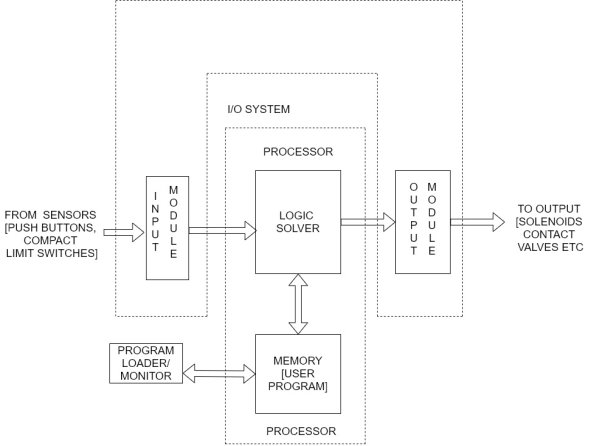
_Input section converters convert the field signals to logic level signals that the PLC is processor can read directory.
_The processor section reads these inputs processes the signals executing the program and prepares the output signals.
_The output section converts the logic level output signals coming from the processor section into high-level signals and releases signals for various fields devices.
_The program loader is used to enter the user’s program into the memory or change it and to monitor the execution of the program.
Input output section
The input output section stablished the interfacing between the real world outside the PLC and the digital arena inside the PLC the signals from machines or instruments of a system are received through the input section by a PLC, after processing the output signals are transmitted to the machines are the instruments for the desired control action through the output section.
Task of the input output section classified as
a) Conditioning
b) Isolation
c) Termination
d) Indication
The field signal available is 220 volt or 440 volt since a PLC can only support voltage of 0-10V, the field signal has to be condition before it is applied to PLC.
To protect a PLC from any incoming surges from the field isolating devices such as a T/F or an up to isolators are used. The input output module provides a proper terminal. It indicates the status of the input output terminal, when the voltage is the status indicator is off.
Processor section
A block diagram of the processor section of a PLC shown in figure
This section consists of four major elements
- Power supply
- Memory
- CPU
- Input output interface
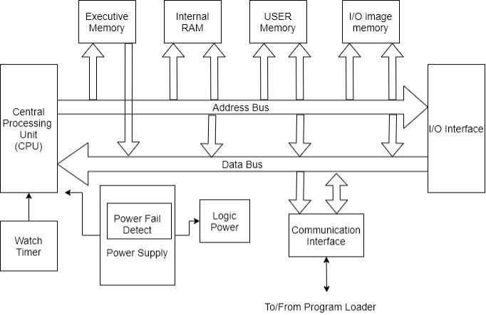
Detailed block diagram of processor section at PLC
Q8) Explain Power supply.
A8) The basic function of the power supply is supply conditioned power to the components of PLC.
The power supply is one of the most critical components of the PLC for two reasons:
a) It is typically known reluctant. Hence, failure of the PLC power supply can cause the entire control system to fail.
b) It contains High voltage components. Hens and insulation failure can be serious potential for injury or fire.
The following guidelines should be followed when choosing the power supply of a PLC:
- The power supply should be packed properly so that the heat generated by the power supply can be dissipated in order to prevent overheating this increases reliability.
- The power supply should be tested for temperature and electrical insulation by a proper certification agency.
- The power supply should meet the at least one reputable standard for rise immunity. It should also be capable of withstanding line voltage variation such as chop outs, broon outs and surges, which are common industrial faults.
- Suitable redundancy will increase reliability.
Q9) Explain types of Memory in PLC.
A9) Two types of memory in PLC
i. Volatile memory
Ii. Nonvolatile memory
Nonvolatile memory is generally used for storing users’ program so that they are preserved during power cuts.
Different types of memory that are generally used in PLC are as follows.
Battery backed up CMOS RAM:-
This is probably the most widely used type of memory all through most Ram’s are inherently volatile the CMOS variety consumers such a small amount of power that a small battery will retain the memory during power loss. The battery used vary from short life primary cells which require periodic replacement after 6 months to air to long life cells which may last upto 10 years.
EPROM Memory:-
Electrical Programmable read-only memory is programmed using electrical passes and can only be raised by exposing the circuit to UV light also caused UV EPROM.
EEPROM memory:-
This memory is similar to EPROM memory but it can also be raised using electrical pulses. In some PLC EEPROM is the only type of memory used. This allows for flexibility of reprogram.
As shown in figure the total memory area is subdivided into four sections namely executive memory section internal RAM, user memory and image memory.
The executive memory holds the executive software and user memory is meant for user program storage the functional explanation of input output image section has been given below.
Functions of input output image memory
- Process image input: - At the beginning of the scan cycle the operating system reads the inputs from the process and record the values in this area the program can use these values in its cycling processing.
- Process image output: - during the scan cycle the program calculates output values and places them in this area. At the end of the scan cycle operating systems reads the calculated output values from this area and send them to the process outputs.
- Bit memory: - this area provides storage for entrance results calculated in the program.
- Timers and counters:- timers are function elements of ladder programming this area provides storage of timer cells. In this area clock timing assesses time cell to update them by decrementing the time value. Counter are functions element of ladder programming this area provides storage for counters. Counter instruction them.
Q10) What is CPU? Explain.
A10)
- The CPU is the heart of the PLC system.
- The CPU used may be smaller or Larger one depending on the size of the process to be controlled.
- It is important to size the system CPU according to the internal memory needed to run the process.
- Controlling the small operation only a small PLC unit with limited memory controlling a larger system would require larger unit with more memory and functions.
- Some CPU's can have additional memory easily added at a later date others cannot be added to or expanded.
- Advanced planning with the manufacturer is required to match present and future needs with the size of the system being purchased.
- Many CPU contains backup batteries that keep the users process control ladder program in storage in the event of the plant power failure.
- The basic operating system is stored permanently in the CPU in read only memory and is not lost when input power is lost.
- However, the user process control ladder diagram being in random access memory is not stored permanently.
- The CPU who all have operational switches some of which require key to prevent unauthorized personal from running a turned off process.
- The key types which also can prevent unauthorizedactoration to the operating system program.
- The switch position varies from manufacturer and manufacturer but are similar typical positions are
a) Off: - system cannot be run or programmed.
b) Run: - allows the system to run but no program attraction can be made.
c) Disable: - Turns all output of or sets them to the in operable state.
d) Monitor: - turns on screen that display operating information.
e) Run/program: - system can run and program modification can be made to it while it is running. This mode must be used with caution. In this mode the program can be completely erase but can only be modified. To delete an entire program the key must be in disable position.
f) Off/program or program: - system cannot run but can be programmed or reprogrammed
Programmer (monitor)
The programmer is connected to the CPU by a cable. After the CPU has been programmed the team is no longer required for CPU and process operation and can be disconnected and removed. Therefore, you may be need only one PM for a number of operational CPU’s. The PM may be moved about in the plant as needed the same pm can be used in the office or lab to pretest program.
Q11) Explain PLC Input and output modules (along with Interfaces).
A11) Input output module are available as either input only output only or a combination of inputs and outputs.
Discrete input module
The discrete input module is the most common input interface used with Programmable controllers discrete input signals from field devices can be either AC or DC.
Discrete AC input module
A 120 volt AC input will accept signals between so and 135 volt AC common inputs include limit switches, proximity, photoelectric switches, selector switches, relay contacts and contact closure from other equipment’s figure illustrates wiring for atypical 120 volt AC input module. The left module has its common connected internally. All inputs will have the same voltage the right module is a 120- or 230-volt AC input module. The module has to separate common which allows the user to write two different input levels.
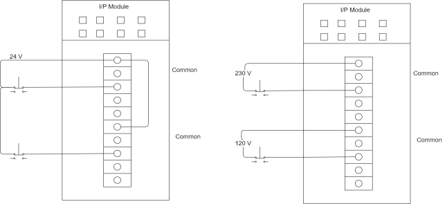
The input module is considered the load for the field input device. The module's job is to convert the 120-volt A.C., high voltage signal to the 5-voltD.C level. With which the PLC can work. The module job is to verify the input as a valid signal,isolate the high voltage field device signal from the lower voltage CPU signal and send the appropriate or off signal to the CPU for placement in the input status file. Does circuitry contain in an input module is composed of three parts:-
Power file conversion, isolation and logic as shown in figure.

Alternating current enters the input module(sections) and then flows to the power conversion section.
Power conversion
The power conversion section usually consists of resistors and a bridge rectifier. The bridge rectifier converts the incoming DC signal to a pulsating DC level (section 3). The DC level is passes through filters and other logic (sections) to deliver a clean de bounced DC input signal (sections). The filtered DC signal goes on to the threshold detector (section 6).
Threshold detection
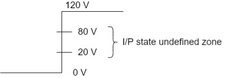
Search for detection circuitry detects if the incoming signal has reached or exceeds pre-determined value for a pre-determined time and weather it should be classified as a valid ON or OFF signal, module specification can thus the valid ON/OFF state vtg range. Atypical valid OFF state is between 0 and 20 or 30V A.C depending upon module manufacture. A valid ON state will be between 80 and 132 2-volt AC. Again depending on the manufacturer, the signal area between the output voltage limit for a valid off state (20 volt) and the minimum voltage for a valid ON state (80 volt) is called the undefined or input state not guaranteed. Signals falling within this undefined area may be ON or OFF making them unstable and reliable.
Isolation
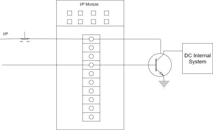
The isolation section of the input circuit is usually made up of and optical isolator for op to coupler. In a 120-volt AC input module isolation separates the high voltage, 120-volt AC input signal from the CPU's low voltage control logic. The low voltage control logic signals associated with the CPU will run from 5 to 18-volt dc, depending on the module manufacturer and the type of logic employed.
Isolation is accomplished by the input signal energizing light emitting diode (LED) which transmits a signal of light energy to receiver in the form of photoconductive diode. Simply put the LED convert the electrical signal to an optical signal. The receiver usually a photo transmitter, convert optical signal back to an electrical signal. There is no actual physical or electrical coupling between the sending LED, its associated circuits and the optical receiver and its 100-voltage associated logic circuitry. The signal is transferred by light from the LED. Figure shows a simplified optical isolator.
The logic sections
DC signals from the opto-coupler are used by the logic section (section 8) to Pan the input signal to the module's input address LED (section 9) and the CPU (section 10)and then onto the input status file via wired on the rack's black plane call the data bus.
The two types of input devices
1) There are two types of input devices commonly interfaced to an input module.
2) One type includes the mechanical limit switch, toggle switch, push button and contacts from an electromechanical relay.
3) Every one of these devices has something in common circuit continuity is either made or broken by physically opening a set of contacts.
4) When open these contacts have a physical air thus there is infinite resistance, resulting in zero current flow through the physically open contacts.
5) Since these are mechanical contacts there no electrical power required to make the device operate.
6) The second type, the solid-state proximity device, On the other hand is an electronic device which means that it needs power to operate.
7) A small all amount of current must continuously flow through the device even in the OFF state to keep the internal electronics working so that the switch will be able to sense the presence of an object.
8) Figure shows the two-wire connection for a solid-state proximity sensor.
9) Notice that there is only a single part for power flow not only to provide the ON or OFF signal the load, but also to provide that small amount of current to operate the internal electronics.
10) The current flowing through the sensor to operate internal electronics is called its Leakage current.
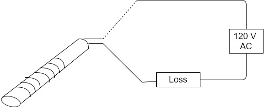
11) Excessive leakage current could possibly cause on input module's input point to turn on in error is the module's maximum off state current is exceeds.
12) Figure shoes 2 inputs going into an input module. Input A is a mechanical limit switch, when the limit switch is open, there exist a physically open circuit, thus, there is zero current flow into input point 0.
13) Input 6 is an inductive proximity switch. Although the switch is in the off or de-energized state and the schematic symbol shows and open circuit must be current flow through the electronics to keep the sensor operating so that it will be able to switch from open to closed when a target comes into range.
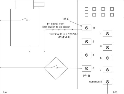
14) Leakage current for a 2-wire sensor is typically less than 2 MA[usually around 1.7 MA].
15) Some larger high-power sensors can have leakage current as high as 3.5 MA or more.
16) Most sensor manufacturer has a standardized leakage current value of less than 2 MA so that we can interface to most PLC's.
17) A typical AC input module will accept leakage current of less than 2 MA and still read the signal as the valid OFF.
DC input module operation
Except for the bridge rectifier circuit, the DC i/p module is very similar to the AC input module. Since the input signal is already. DC, no bridge rectifier is necessary. Resistors are used to drop the incoming voltage before passing the signal onto the remaining electronics. Figure shows A simplified block diagram for DC i/p module.

Discrete output modules
1) Much like discrete i/p discrete o/p are the most commonly used type.
2) Discrete o/p module simply acts as switches to control o/p field devices. They fall into two classification- solid state o/p switching and relay output switching.
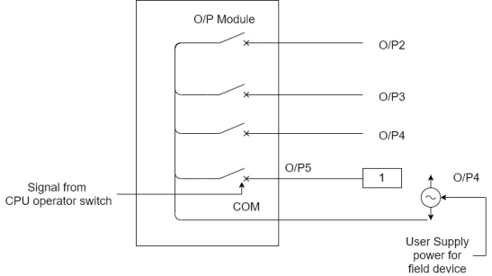
3) Discrete o/p module receives their operating power from the PLC's power supply.
4) Usually the user must provide the power that the module o/p switches to control the field devices.
5) Figure shows basic field wiring for discrete 120 V AC o/p modules.
6) Discrete output module comes in various signal levels and specifications.

Solid state output module switching
1. A typical AC o/p module contains circuitry as shown in block diagram.
2. A single AC o/p point consists of a latching circuit for the low voltage [12-18V de] logic signal sent by the CPU from the o/p status table.
3. The ON /OFF signal represents the logical value of o/p.
4. If the o/p status table bit is 1 the own signal will be latched into the logic circuitry block.
5. This ON signal will be passes through the optical isolation circuitry to the block containing the switching hardware.
6. In a solid-state AC o/p module, a triac is used to switch the AC high voltage and current controlling the ON or OFF state of the field hardware device.
7. A traces a solid-state device used to switch AC.
8. The filter block will contain protective devices such as a metal oxide varistor (MOV)
9. The MOV is used to limit peak voltage across the AC switching hardware to a safe value.
10. The o/p points LED alerts the operator that the o/p has been directed by the CPU to turn ON
11. The tube may also be included on the o/p line to protect the easy switching device from drawing too much current.
Relay output module
1. Relay o/p modulus r are also known as Contact o/p or dry contact o/p.
2. Even through relay o/p module are used to switch AC or DC loads. Usually relay o/p are used to switch small currents at low voltages to multiplex analogue signals and to interface control signals to variable speed drives.
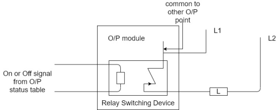
3. Relay o/p modules use actual mechanical relay one for each o/p status file.
4. Figure shows one point of relay o/p module. Notice that common goes to the other relay in the group.
5. Relay o/p what DU user available in three variations depending on the manufacturer.
6. Most manufacturers offer combination i/p and relay o/p module.
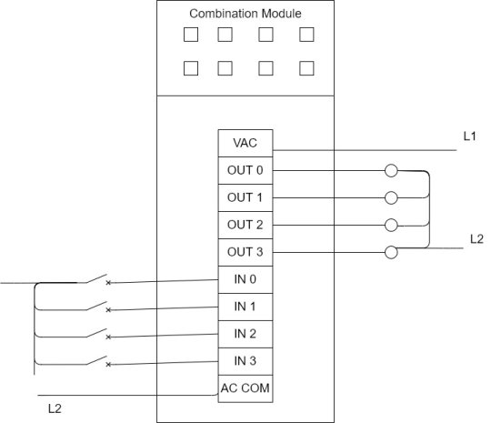
7. Combination relay module usually come with two, four or six 120 V AC i/p and two, four or six relay o/p.
8. Following figure shows 4-point 120 V AC i/p and a 4-point relay o/p combination module. Notice that relay o/p accepts AC or DC signals.
Q12) Write Specifications about CPU and Digital Input Module.
A12)
1. Central processing Unit
a. System characteristics: Should be programmed with STEP 7 or higher, Automatic routing via PROFINET / Profibus, independent of network Data block routing via PROFINET / Profibus Integrated Web server functionality Integrated communication services (TCP/IP, UDP, ISO on TCP, SNMP, NTP, PROFINET CBA/IO) Isochronous operation on the bus system
b. Integrated work memory: 384 Kbyte
c. Integrated load memory: 8 MByte
d. No. Of timers: 256
e. No. Of counters: 256
f. No. Of bit memories: 2048 Byte
g. Processing times for bit-operations, min.: 0,05 µs for word operations: 0,09 µs for arithmetic operations: 0,12 µs for floating point arithmetic: 0,45 µs
h. Interfaces MPI (RS485), PROFIBUS (RS485), PROFINET (RJ 45-Ethernet), Integrated PROFINET Switch
i. Integrated functions Real-time clock, Buffer time 6 weeks, Password protection
j. Supply voltage Rated value: 24V DC
2. Digital Input Module
- Supply voltage 24 V DC Yes
Permissible range, lower limit (DC) 20.4 V
Permissible range, upper limit (DC) 28.8 V
2. Number of digital inputs 16
3. Input voltage Rated value, DC for signal "0" for signal "1" 24V -30 to +5 V 13 to
30V.
4. Input delay for standard inputs Programmable 0.1/.5/3/15/20 ms 5 Status display Sensor supplies Green LED per channel Green LED per group 3 Galvanic isolation between channels Groups of 16 4 Opto isolation between channels and backplane Opto isolation.
5. Permissible potential difference between different circuits 75 VDC/ 60 VAC
6. Isolation 500 VDC
7. Features Isochronous mode, programmable diagnostics, programmable diagnostics interrupt, programmable hardware interrupts, 2 short circuit proof sensor supplies for each group of 8 channels, support for external redundant sensor supply
8. Connection method 40-pin front connector
Q13) What are the Advantages and Disadvantages?
A13) Advantages of PLC
1) Flexibility: - In the past each different electronically controlled production machine required its own controller. Now it is possible to use just one model of a PLC to run any one of the 15 machines.
2) Implementing changes: - With wired, relay type panel, any program alteration required time for rewiring of panels and devices. When a PLC program circuit or sequence design change is made. The PLC program can be changed from a keyboard sequence in a matter of minutes.
3) Large quantity of contacts: - The PLC has a large number of contacts for each coil available in its programming. Suppose that a panel wired relay has four contacts and all are in use when a design change requiring three more contact is made. Time would have to be taken to rock your and install a new relay for relay contact block. Using a PLC however only three contacts around be typed in. The three contact would be automatically available in the PLC.
4) Lower cost: - increased technology makes it possible to condense more functions into smaller and less expensive packages. Now you can purchase a PLC with numerous relay timers and counters a sequence and other and other functions for under hundred dollars.
5) Pilot running: - A PLC programmed circuit can be evaluated in the office or the program can be typed in, tested, observed, and modified if needed saving valuable for time. In in contrast conventional relay system have been best tested. On the factory this can be very time consuming.
6) Visual observation: - A PLC circuit operators can be seen during operation directly on a CRT screen. The operation or mis operated of a circuit can be observed as it has logic path light up on the screen as they are energized. Troubleshooting can be more quickly during visual observation.
7) Speed of operation: - Relays can take an acceptable amount of time to actuate. The operation speed of the PLC program is very fast. The speed of the PLC logic operation is determined by scan time which is a matter of milliseconds.
8) Ladder or Boolean programming method:- the PLC programming can be accomplished in the letter made by an electrician or technician. Alternative a PLC programmer who alorksin digital or Boolean control system can also easily perform PLC programming.
Disadvantages of PLC:-
1. New technology: - It is difficult to change the thinking of some personal from ladders and relays to the PLC computer concept. Although today, with pervasive use of computers not only at home and in the office but on the factory floor acceptance of the computer as a powerful and reliable productivity enhancing tool is, if not universal almost so.
2. Fixed program applications: - Some applications are single function. It does not pay to use a PLC that include multiple programming capability is if they are not needed.
3. Environmental considerations: - Certain environments such as high heat and vibration interphase. With electronic devices in PLC's which limit their use.
4. Fail - safe operation:- In relay systems, the stop button electrically disconnects the circuit. If the power fails, the system stops. Furthermore, the release system does not automatically restart when power is restored. This of course can be programmed into the PLC, however in some PLC programs, you may have to apply an input voltage to cause a device to stop. These systems are not failing safe. This disadvantage can be overcome by adding safety relay to PLC system.
5. Fixed circuit operation:- if the circuit in operation is never altered, a fixed center system must be less costly than a PLC. The PLC is most effective when periodic changes in operation are made.
Q14) Explain Selection criteria of PLC.
A14)
1) Understand a process to be controlled.
a) number and types of i/p's or o/p's.
b) Determine how the process is controlled.
c) Determine special needs as distance between part of process.
2) Vendor research may be selected as.
a) Manuals and documentation.
b) Support while developing program.
c) Range of product available.
d) Support while troubleshooting.
e) Shifting time of emergency replacement Training.
3) Memory:- Often 1k and above. It depends on ladder logic program.
4) Scan time:- ladder instruction.
5) Communication.
6) Software:- determine programming and debugging ease.