Unit – IV
Unit – IV
Unit – IV
Unit – IV
Advanced Function and Application of PLC
Q1) What are Analog PLC operation and PLC analog signal processing?
A1) Analog Inputs
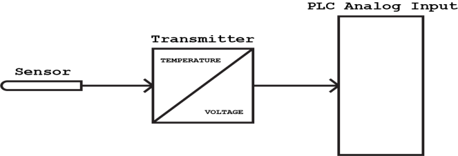
Analog inputs can come from a variety of sensors and transmitters or both. For example one the thermocouple types connected to a transmitter, which is then connected to a PLC analog input. You can measure a whole bunch of different things. The job of the sensor or transmitter is to transform that into an electrical signal. Here are a few of the things you can measure with analog sensors:
- Level
- Flow
- Distance
- Viscosity
- Temperature
Of course, there are many other things you can measure. The main point here is that we (the sensor or transmitter) will transform those physical values into an analog signal. It is that signal we can use in out PLC as an analog input.
An example here could be a temperature transmitter with a 4-20 mA output. Connected to the transmitter is a temperature sensor. The transmitter is then calibrated to a range of e.g. 0-100 degrees. What this means is that when the temperature is 0 degrees the output of the transmitter will be 4 mA, and 20 mA by 100 degrees. A transmitter is often needed because the sensor in itself cannot provide us with an analog signal. Or at least not one that fits a PLC analog input. It is possible to buy analog input modules where you can connect a temperature sensor for example directly. But most often you will have a voltage or current input module where you connect a transmitter.
Q2) Explain PID principles.
A2) A proportional integral derivative (PID) controller can be used as a means of controlling temperature, pressure, flow and other process variables. As its name implies, a PID controller combines proportional control with additional integral and derivative adjustments which help the unit automatically compensate for changes in the system.
PID Controller Basics
The purpose of a PID controller is to force feedback to match a setpoint, such as a thermostat that forces the heating and cooling unit to turn on or off based on a set temperature. PID controllers are best used in systems which have a relatively small mass and those which react quickly to changes in the energy added to the process. It is recommended in systems where the load changes often and the controller is expected to compensate automatically due to frequent changes in set point, the amount of energy available, or the mass to be controlled.
PID Controller Working Principle
The working principle behind a PID controller is that the proportional, integral and derivative terms must be individually adjusted or "tuned." Based on the difference between these values a correction factor is calculated and applied to the input. For example, if an oven is cooler than required, the heat will be increased.
Here are the three steps:
i) Proportional tuning involves correcting a target proportional to the difference. Thus, the target value is never achieved because as the difference approaches zero, so too does the applied correction.
Ii) Integral tuning attempts to remedy this by effectively cumulating the error result from the "P" action to increase the correction factor. For example, if the oven remained below temperature, “I” would act to increase the head delivered. However, rather than stop heating when the target is reached, "I" attempts to drive the cumulative error to zero, resulting in an overshoot.
Iii) Derivative tuning attempts to minimize this overshoot by slowing the correction factor applied as the target is approached.
Q3) What are Typical continuous process control curves?
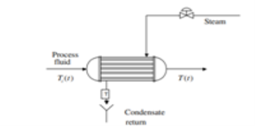
A3) Let us consider a heat exchanger in which a process fluid is heated by condensing steam; the process is sketched. Heat the process fluid from some inlet temperature, Ti(t), up to a desired outlet temperature, T(t).
The energy gained by the process fluid is provided by the latent heat of condensation of the steam. In this process many variables can change, causing the outlet temperature to deviate from its desired value. If this happens, some action must be taken to correct for this deviation.
The objective is to maintain the outlet process temperature at its desired value. One way to accomplish this objective is to first measure the temperature, T(t), compare it to its desired value, and based on this comparison, decide what to do to correct for any deviation.
The steam valve can be manipulated to correct for the deviation. That is, if the temperature is above its desired value, the steam valve can be throttled back to cut the steam flow (energy) to the heat exchanger. If the temperature is below its desired value, the steam valve could be opened more to increase the steam flow to the exchanger.
The operator can do all of this manually, and since the procedure is fairly straightforward, it should present no problem. However, there are several problems with this manual process control.
First, the job requires that the operator look frequently at the temperature to take corrective action whenever it deviates from the value desired.
Second, different operators would make different decisions as to how to move the steam valve, resulting in inconsistent operation.
Third, since in most process plants hundreds of variables must be maintained at a desired value, this correction procedure would require a large number of operators. Consequently, we would like to accomplish this control automatically.
That is, we would like to have systems that control the variables without requiring intervention from the operator. This is what is meant by automatic process control.
To accomplish this objective, a control system must be designed and implemented. The first thing to do is to measure the outlet temperature of the process stream. This is done by a sensor (thermocouple, resistance temperature device, filled system thermometers, thermistors, etc.). Usually, this sensor is connected physically to a transmitter, which takes the output from the sensor and converts it to a signal strong enough to be transmitted to a controller. The controller then receives the signal, which is related to the temperature, and compares it with the value desired. Depending on this comparison, the controller decides what to do to maintain the temperature at its desired value. Based on this decision, the controller sends a signal to the final control element, which in turn manipulates the steam flow. This type of control strategy is known as feedback control.
Q4) What are Simple closed loop systems? Also explain problems with Simple closed loop systems.
A4) When a control system is designed such that it receives operating information from the machine and makes adjustments to the machine based on this operating information, the system is said to be closed loop system as shown in figure below.
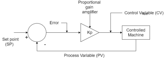
1) The operating information that the controller receiver from the machine is called as process variable (PV) or feedback.
2) The input from the operator that tells the controller the desired, operating point is called the set point (SP).
3) When operating the controller determines whether the machine needs adjustment by comparing (by subtraction) the set point and the process variable to produce a difference. (The difference is called the error)
4) The error is amplified by a proportional gain factor  the proportional gain amplifier (sometimes called as amplifier).
5) The output of the proportional gain amplifier is the control variable (CV) which is connected to the controlling input of the machine.
6) The controller takes appropriate action to modify the machine operating point until the control variable and the set point are nearly equal.
Problems with simple closed loop: -
1) Only a very few types of closed loop system will work correctly when design.
2) The reason is that in order for the machine operating. To be near to the value of the SP, the proportional gain  must be high.
3) However, when high gain is used, the system becomes unstable and will not adjust its CV correctly.
4) Additionally, if the controlled machine has a delay between the time a CV signal is sent to the machine and the time that the machine responds the control system will tend to overcompensate and over correct for the error.
5) To see why these are potential problems considered a closed loop system that controls the speed of a DC motor as shown in figure.
6) In this system the output of the proportional gain amplifier power the DC motor.
7) The PV for the system is provided by a tacho generator connected to the motor shaft.

8) The tacho generator simply outputs a DC voltage proportional to the rotating speed of the shaft.
9) It appears that if we make the SP same as the tacho generators output (the PV) at the desired speed, the controller will operate the motor at the speed. However, this is not the case.
10) When the operator inputs a new SP value to change the motor speed the control system begins automatically adjusting the motor speed.
11) However, if the proportional gain amplifier has a low gain  response to the new SP is slow sluggish and inaccurate.
12) The reason for this is that as soon as the motive begins accelerating, the tacho generator begins outputting and increasing voltage as the PV.
13) When increasing PV voltage is subtracted from the fixed SP it produces a decreasing error.
14) This means the sea we will also decrease which in turn will cause the motor speed to increase at a slower rate. This causes the response to be sluggish.
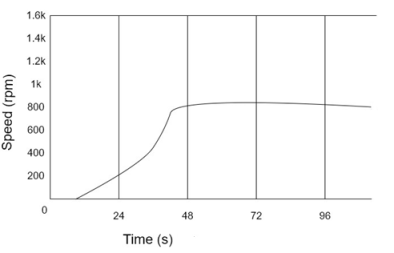
Figure 1 is a graph of the speed of a DC motor with respect to time as motor is accelerated from 0 to SP of 2000 RPM using a closed loop control with low proportional gain. Notice how the motor acceleration is reduced as the motor speed increases which cause the system to takeover 90 seconds to settle and notice that the final motor speed is approximately 350 RPM below the desired set point speed of 2000 RPM. This is called off set.
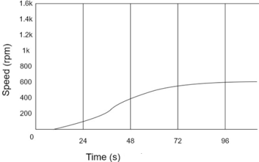
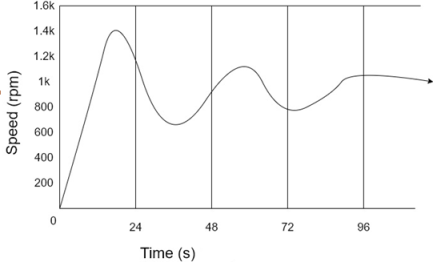
In an attempt to improve both sluggish response and the offset in our motor speed control we will now increase the proportional gain  . Figured is a graph of a same system with proportional gain
  doubled. Notice in this case that the motor speed responds faster, and the final speed is closer to the SP. However this system still takes more than a minute to settle and to offset is more than 200 RPM below the SP.
Since doubling the proportional gain  seemed to help the response done and the offset of our system. We will now try a large increase in the proportional gain. Figure a choose the response of our system with the gain
  increased by a factor of 10. Lotus that the offset is smaller (approximately 25 RPM below the SP) however the response now oscillates to both sides of the SP before finally setting. This decaying oxidation is called hunting and in some systems is generally undesirable.
It can potentially damage machine with the over stress of mechanical all systems and the over speed of motors. In addition, it is counter produce because although our motor speed increased rapidly the system still required nearly 2 minutes to settle.
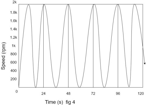
If we increase the proportional gain even more the system becomes unstable. Figure shows this condition which is called oscillation. It is extremely undesirable and if ignored we likely be destructive to most close loop electromechanical systems. Any further increase in the proportion game will cause higher amplitude of oscillation.
Q5) Explain Closed loop system using Proportional, Integral and Derivative (PID).
A5)
1) In the example previously used to there were three fundamental problems with the simple system using only proportional gain.
2) First the system had a large offset, second it was slow to respond to changes in the SP (both of these problems were caused by a low proportional gain and third when the proportional game was increased to reduce the offset and minimize the response time the system becomes unstable and oscillated.
3) It was impossible to simultaneously optimize the system for offset fast response and high stability by turning only the proportional gain.
4) To improve on this arrangement, we will add two more functions two our closed loop control system which are an integral function KS and a derivative function  shown.
5) The error signal is amplified by KP and then apply to the integral and derivative functions.
6) The outputs of the proportional gain amplifier  integral function Kis and the derivative function
  added together at the summing junction to produce CV.
7) The values of multiplying constant that are adjusted by the system designed and are almost always set to a positive value or zero.
8) If a function is not needed its particular K value is set to zero.

9) The PID system shown in above figure is cost as ideal PID and is the most commonly used PID configuration for control systems.
10) There is another popular version of the PID called the parallel PID for electrical engineering PID in which three function blocks (proportional integral and derivative) are connected in parallel as shown below.
11) When popular tunes the parallel PID performs identical to the ideal PID.
12) However the values of  The parallel PID will be larger by a factor of K because the input to this function is not free amplified by
 in ideal PID.

Derivative function
1) Now applied the derivative function to our motor control system as shown in figure.
2) For this exercise we will be adjusting the proportional gain  and derivative game
  only.
only.
3) The integral function will be temporarily disabled by setting  to zero.

4) Previously when we increase the proportional gain of our simple closed loop DC motor speed system, it begins to exhibit in stability by hunting.
5) Without changing the proportional gain now increase the derivative gain
  a small amount. The resulting response is shown in figure.
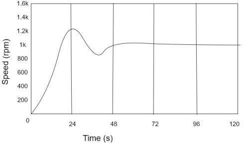
6) If comparison is made, the motor speed accelerates at time  the top speed that the motor reaches while the system is hunting and the length of the time it takes the speed to zero.
7) First at time t=0 the SP switch from 0 to a voltage corresponding to a motor speed of 2000 RPM.
8) Since the motor is not rotating, the tattoo generator output will be zero and the PV will be zero.
9) Therefore, the error voltage at this instant will be identical in amplitude and wave shape to the SP.
10) At time zero when the SP is switched on the wave shape will have a very high-rise time which in turn will cause the derivative function to output a very large positive sign.
11) This derivative output will be added to the output of the proportional gain function to form the CV.
12) Mathematically the CV and time 

Where  the slope of the S P wave.
13) Since the slope  extremely large at
  be large and cause the motor to begin accelerating very rapidly.
Integral function
1) In a closed loop system whenever, there is an offset in the response there will be a non- zero error signal.
2) This is because the PV at the SP are not equal.
3) Since the integral function input is connected to the same error signal as the derivative function in the integral will began to sum the error over time.
4) For large offset, the integral will accumulate rapidly, and its output will increase quickly.
5) For smaller offset, the integral output will change more slowly.
6) However, note that as long as the offset is nonzero the integral output will be changing in the direction that will reduce the offset.
7) Therefore, in a closed loop PID control system can reduce the offset to bear zero by increasing the integral gain constant to some positive value.
8) Give four we will now attempt to reduce the offset in our motor speed control example to zero by activating the integral function.
9) Figure shows the result of increasing 
10) Note that the transient response has changed little but after setting the offset is now 0.
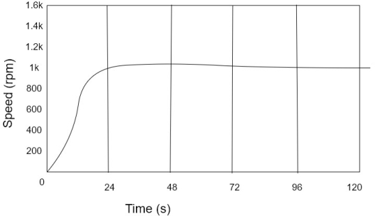
11) It is not advisable to make the integral gain constant  excessively high.
12) Doing so causes the integral and proportion function to begin working against each other which will make the system more unstable.
13) System with excessive values of  will exhibit overshoot and hunting and may oscillate.
Q6) Explain PID in Programmable Logic controllers.
A6)
1) Although the general PID concepts and effect of adjusting  onstant are same, when using a Programmable Logic controller to perform a PID control function there are some minor differences in the way the PID is adjusted.
2) The PID control unit of a PLC performs and the necessary PID calculations on an interactive basis.
3) that is the PID calculations and not done continuously but are triggered by a timing function.
4) When the timing trigger occurs the PV and SP are sampled once and digitized and then are of the proportional, integral, and derivative functions are calculated and summed to produce the CV.
5) The PID then posed waiting for the next trigger.
The exact parallel PID expression is

6) However, since the PLC performs discrete integral and derivative calculations based on the sampling time interval ∆the discrete PID performed by a PLC is

7) In the numerical integral portion of above can since SP-PV is the error signal then. is the sum of the areas (the error times the time interval)?
8) The numerator term ∆(SP-PV) is the present error signal minus the error signal measure in the most recent sample.
9) Additionally, in order to make the PID tuning methodical most PLC manufactures have replaced  is termed the reset time constant or integral time constant.
10) The reset time constant  the inverse of the integral gain constant.
11) For same reason the derivative gain constant been replaced with the derivative time constant
12) Therefore, when tuning a PLC operated PID controller the designer will be adjusting the three constants  . Using these constant a mathematical expression became

Q7) Explain PID Modules.
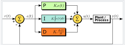
A7) The distinguishing feature of the PID controller is the ability to use the three control terms of proportional, integral and derivative influence on the controller output to apply accurate and optimal control. The block diagram on the right shows the principles of how these terms are generated and applied. It shows a PID controller, which continuously calculates an error value as the difference between a desired set point and a measured process variable and applies a correction based on proportional, integral, and derivative terms. The controller attempts to minimize the error over time by adjustment of a control variable such as the opening of a control valve, to a new value determined by a weighted sum of the control terms.
In this model:
Term P is proportional to the current value of the SP − PV error e (t). For example, if the error is large and positive, the control output will be proportionately large and positive, taking into account the gain factor "K". Using proportional control alone will result in an error between the set point and the actual process value, because it requires an error to generate the proportional response. If there is no error, there is no corrective response.
Term I accounts for past values of the SP − PV error and integrates them over time to produce the I term. For example, if there is a residual SP − PV error after the application of proportional control, the integral term seeks to eliminate the residual error by adding a control effect due to the historic cumulative value of the error. When the error is eliminated, the integral term will cease to grow. This will result in the proportional effect diminishing as the error decreases, but this is compensated for by the growing integral effect.
Term D is a best estimate of the future trend of the SP − PV error, based on its current rate of change. It is sometimes called "anticipatory control", as it is effectively seeking to reduce the effect of the SP − PV error by exerting a control influence generated by the rate of error change. The more rapid the change, the greater the controlling or dampening effect.
Q8) Explain types of PID tuning.
A8) Manual Tuning
With enough information about the process being controlled, it may be possible to calculate optimal values of gain, reset and rate for the PID controller. Often the process is too complex, but with some knowledge, particularly about the speed with which it responds to error corrections, it is possible to achieve a rudimentary level of tuning.
Manual PID tuning is done by setting the reset time to its maximum value and the rate to zero and increasing the gain until the loop oscillates at a constant amplitude. (When the response to an error correction occurs quickly a larger gain can be used. If response is slow a relatively small gain is desirable). Then set the gain of the PID controller to half of that value and adjust the reset time so it corrects for any offset within an acceptable period. Finally, increase the rate of the PID loop until overshoot is minimized.
Auto Tuning
Most process controllers sold today incorporate auto-tuning functions. Operating details vary between manufacturers but all follow rules similar to those described above. Essentially, the PID controller “learns” how the process responds to a disturbance or change in set point, and calculates appropriate PID settings. In the case of a temperature controller like OMEGA’s Platinum series, when “Auto Tune” is selected the controller activates an output. By observing both the delay and rate with which the change is made it calculates optimal P, I and D settings, which can then be fine-tuned manually if needed. (Note that this controller requires the set point to be at least 10°C above the current process value for auto tuning to be performed).
Newer and more sophisticated PID controllers, such as OMEGA’s Platinum series of temperature and process controllers, incorporate fuzzy logic with their auto tune capabilities. This provides a way of dealing with imprecision and nonlinearity in complex control situations, such as are often encountered in manufacturing and process industries, and helps with tuning optimization.
Q9) What are Adjust and observe tuning method? Explain.
A9)
1) As the name implies the “adjust and observe” tuning the method involves the making of initial adjustments to the PID constant observing the response of the machine and then knowing how each of the functions of the PID perform making additional adjustments to correct for undesirable properties of the machine’s response.
2) From our previous discussion of PID performance we know the following characteristics of PID adjustment.
3) Increasing the proportional given will result in a faster response and will not eliminate offset however at the same time increasing proportional given will also cause overshoot hunting and possible oscillations.
4) Increasing the derivative time constant  it will reduce the hunting and overshoot caused by increasing the proportional gain however it will not correct for offset.
5) 5)Decreasing the integral time constant will cause the PID to reduce offset to zero, smaller value of  cause the PID to eliminate the offset at a faster rate excessively small value of
 will cause integral oscillation.
6) The adjustment procedure is as following
7) Initiative the PID without. This is done by dissembling derivative and integral functions by setting both and setting
 an initial value between 1 and 5.
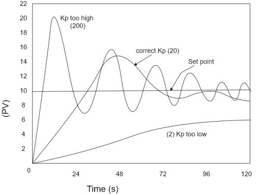
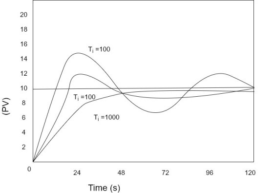
8) With the machine operating quickly move the set point to a new value and observe the response. Figure shows some difficult responses with a set point range from 0 to 10 for various values of  preliminary adjustment of
  result in response with an overshoot i.e. approximately 10 to 50% of set point. Actors. In adjustment process we are not concerned about the minor amount of hunting the offset. Their problem will be connected further by adjusting
  respectively.
9) There is usually large range that  for this adjustment. E.g. The three responses shown in figure were
  of 220 and 200 for this particular system although
 not be the final value.
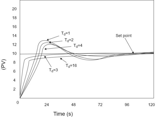
10) Increase  the overshoot is reduced a desired level. If no overshoot is desired this can also be achieved by future increase in
  figure shows system with
 and several trial values of
 for our system we will attempt to tune the PID to provide minimal overshoot so we will use the value of
11) Adjust that the PID will eliminate the offset since
  the inverse of
  this adjustment should begin with high values of
  and then be reduced to achieve the desired response. For this adjustment
  values that are too large will cause system to be slow on eliminating the offset. Values of
  that are too small will cause the PID system to correct one offset to quickly and it will tend to oscillate. Figure shows example system with
  and values of 1000,100 and 10 for
  . If we are tuning the system for minimal overshoot the value
  is good choice.
12) Once the initial PID tuning is complete the designer main now make further adjustments to the three constants if advised. From the starting point the designer has the option to vary proportional gain  over a wide range. This can be done to obtain faster response to a set point change. If system is to operate with varying loads, it is externally important to test it for system stability under all load conditions.
Q10) Explain AC motor starter.
A10)
1) In the simplest form a motor starter performs two basic functions.
2) First it allows the machine control circuitry (which is low vtg, low current, and other DC single phase AC) to control a high current, high vtg phase motor.
3) This isolates the dangerous hi vtg particle of the machine circuits from the safer low voltage control circuits.
4) Second, it prevents the motor from automatically starting for resume making when power is applied to the machine, even if Power is removed for a very short interval.
5) Motor starters are commercially available devices.
6) At a minimum they include a relay (in this it is called a contactor) with three heavy duty N/o main contacts to control the motor, one night duty, N/o auxiliary contacts that is used in the control circuitry and one night duty, N/c overload contact that opens if a current overload condition occurs.
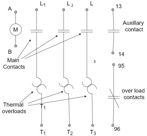
7) Most starters have terminal labels (letters and numbers) molded into the body of the starter next to each screw terminal that the designer may reference on schematic diagram.
8) The coil of the contactor actuates the main contacts and the auxiliary contact at the same time.
9) The overload contact is independent of the contactor coil and only operates under and overloads condition.
10) More complex starters we have 4 or more main components (instead of three) to accommodate other motor wiring configuration and extra auxiliary and overload contact of either the N/o or N/c type.
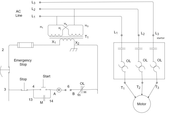
1) Above figure shows one method of connecting the starter into the machine control circuitry.
2) The terminal number on the schematic correspond to those on the motor starter schematic.
3) Power from the three phase line is applied to terminal  the starter while the motor to be controlled is connected to terminal
4) When the rails are powered when the START switch provide power to the motor starts coil M.
5) As long as the overload contacts OL are closed, the motor starter will activate, and three phase power will be provided to the motor.
6) When the starter actuates auxiliary contact M closes, which bypasses the START switch.
7) At this point, the START switch no longer needs to be pressed in order to keep the motor running.
8) The motor will continue to run until
- Power fails
- Emergency stop button is pressed
- The stop switch is pressed
- The overload contact OL opens
9) When any one of these four events occur, the motor starter coil M be energized, the three-phase line to the motor is interrupted and the auxiliary contact M opens.
Q11) What is AC motor overload protection? Explain.
A11)
1) For most applications AC induction motor are overload protected at their rated current.
2) Rated current is the current in each phase of the supply line when operating at rated load and is always listed on the motor nameplate.
3) Overload protection is required to prevent damage to the motor and feed circuits in the event a fault condition occurs which includes a blocked rotor and internal electrical faults.
4) In general, simple single-phase fuses are not used for motor overload protection.
5) When a motor is started, the starting currents can range from 5 to 15 times the rated full load current.
6) Therefore, a fuse that is sized for rated current would glow when the motor is started.
7) Even worse, since we would need to fuse each of the three phases powering a motor, if only one of the fuses words to blow the motor would go into a single phasing condition.
8) In this case the motor shaft may continue to rotate but the motor will operate at a drastically reduced efficiency causing late to the overheat and eventually fail.
9) Therefore, the motor overload protection must
- Ignore short term excessive current that occurs during motor
- Simultaneously interrupt all three phases when an overload condition occurs.
10) The solution to the potential single facing problem is to connect current sensing device called an overload. In series with each of the three phases and two mechanically sync them so that when any of the three overloads sensors and will current conditions, it opens a contact.
11) The overcurrent contact is connected in into the motor starter circuits so that when overload contact opens, the entire starter circuit is disabled. Which in term opens the 5-phase motor contactor interrupting all three phases powering the motor.
12) The tripling problem is overcome by designing the overloads to reset slowly and therefore not hip when a short-term overload occurs, such as the normal starting of the motor.
13) The most popular type of overload is the thermal overload. Although come thermal uploads are bimetallic temperature switch, the more popular type of thermal overload is the eutectic metallic alloy overload.
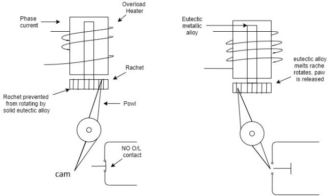
14) This device consists of eutectic alloy, which is heated by an electrical coil through which the phase current passes.
15) If the phase current through the overload heater is excessive the eutectic metal will eventually melt.
16) This releases a rutchet which comes the normally closed overload contacts into the open position.
17) In order to make the overload reusable, the eutectic alloy in the overload is sealed in a tube so that it will not leak out when it melts.
18) The reacted tube, eutectic metallic alloy and spinelle are commonly called overload.
19) When the overload cools and eutectic alloy solidifies the rutchet again will be prevented from rotating and overload can be reset bye manually pressing lever.
20) Major advantage in using the thermal overload is that as long as overload is properly sized for the motor, the overload heats in much the same manner as the motor itself.
21) Therefore, temperature of the overload is a good conductor of the temperature of motor windings.
22) However, the designer must consider any ambient temperature difference between the motor and overload.
23) If the motor and overload cannot be loaded in the same area the overload size must readjusted using temperature correction faster.
24) Another advantage in using this type of overload is that the starter can be resized to a different hip current by simply changing the overload.
Q12) Explain DC motor control with ac power source.
A12)
1) In order to operate a DC motor from an AC source the AC power must first be converted to DC.
2) It should be noted that the DC used to operate a DC motor need not to be a continuous non varying voltage.
3) It is permissible to provide DC power in the form of half wave rectifier or full wave rectifier power or even pushed off power.
4) A few wave rectifier circuits shown in figure will power DC motor armature. However, in this circuitry the average DC voltage applied to the armature will be dependent on the AC line voltage.
5) If we desire to control the speed of the motor, we will need the ability to vary the AC line voltage.
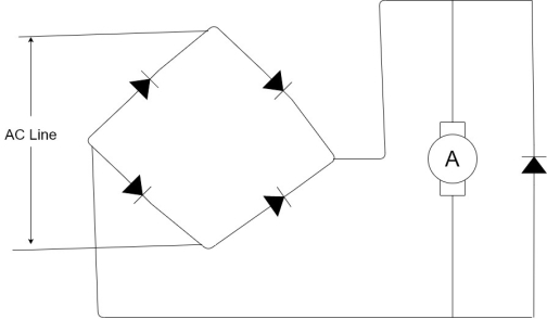
6) To provide control over the average DC vtg apply to the motor without the need to vary the line voltage. We will replace two of the rectifier diodes in our bridge with SCR's as shown in figure.
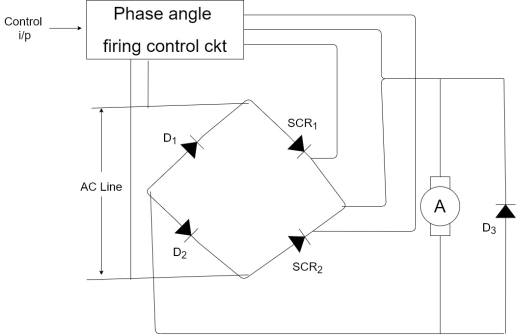
7) Note in the above CK+ it is not necessary for all four rectifier diodes to be SCR.
8) The reason is that the remaining two diodes, e simply steering diodes that route the restart current from the armature back to the opposite side of the AC line.
9) Therefore, we can completely control current flow in the circuit with the two SCR shown.
10) The phase angle firing control  onitors the sine wave of the easy line and produces a precisely timed pause to the gate of each of the SCR's.
11) This will ultimately control the magnitude of the average DC voltage applied to the motor armature.
12) We will begin analyzing our circuit using the two extreme modes of operation which are when SCR fully OFF and fully ON.
13) First assumes that the firing Centre circuit produces no signal to the gate of the SCR's
14) In this case, the SCR’s will never fire and there will be zero current and zero voltage applied to the motor armature.
15) In the other case, assume that the firing control circuit provides a short pulse to the gate of each SCR at the instant that the anode to cathode vtg off the SCR became positive (which occurs at 0° in the applied sin wave for SCR 1 and 180° for SCR 2)
16) When this occurs, the SCR's will alternate leaf fire and remain fire for their entire respective half gate of the Sine wave.
17) In this case, the two SCR's will act as they are rectifier diodes and the circuit will perform as in first figure with the motor operating at full speed.
18) Now consider the condition in which the SCR are fixed at same delayed time after their respective anode to cathode vtg ( came positive.
19) In this case there will be a portion of the half wave rectified sine wave missing from the output waveform which is the portion from the time the waveform starts at zero until the time the SCR is fired.
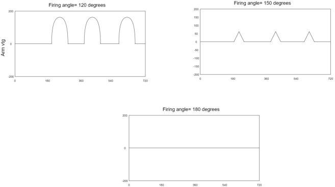
20) When we fire the SCR at some delete time, we generally measure this time delay as a trigonometric angle [called the firing angle]. With respect to the positive slope zero crossing of the Sine wave of the line voltage.
21) Following figure shows the armature vtg for various firing angle between 0 degree and 180 degree.
22) Notice that as the SCR firing angle increases from 20 degree to 180 degree, the motor armature voltage decreases from full vtg to zero.
Q13) Explain DC motor control with DC power source.
A13)
1) Consider the following figure, we have DC vtg source  resistor R, inductor L, diode D and a semiconductor switch Q (shown here as an n-channel isolated Gate)
2) The signal applied to the gate of the switch Q is a pulse train with constant frequency (and constant period T), but with varying pulse width.
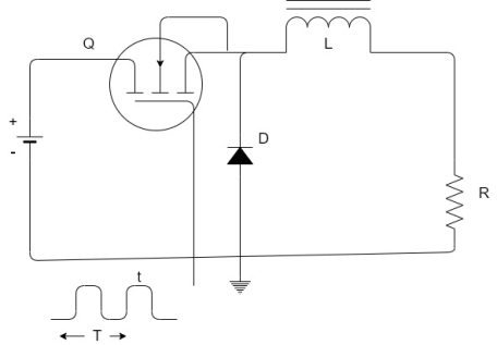
3) The relative value of R and L are selected such that the time constant is at least 10 times the period of the pulse train applied to the gate.
4) For the switch Q the ratio of the on-time t to the period T is defined as the duty cycle and represented as a percentage between 0% and 100%.
5) If we apply pulse train with a 0% duty cycle to the gate, the switch will remain off all of the time add the voltage on the resistor R will obviously be zero.
6) In a similar manner if we apply a pulse train with a duty cycle of 100%, this which will remain on all the time, the diode D will reverse biased and after 5 time constant, the vtg on the resistor R will be V.
7) For any duty cycle between 0% and 100%, the average resistive voltage will be corresponding percentage of the vtg V.
8) For example, if we adjust the applied get pulses so that the duty cycle is 35% (i.e. ON for 35% of the time, OFF for 65% of the time), then the vtg on the resistor R will be 35% of the input vtg V.
9) This is because during the time the switches on the inductor will store energy during the time the switches of the inductor will give up some of the stored energy keeping current flowing in the circuit through inductor L, resistor R and the forward biased diode D (in this application the diode is called freewheeling or commutating diode)
10) The average voltage is controlled by the duty cycle of the switch whenever the duty cycle is changed the voltage on the resistor will settle within five L/R time constant.
11) Since the armature windings are made from copper wire, there will be distributed resistance in the coils  then the coils themselves will give the armature distribution inductance
12) Therefore, we generally model the armature as a lumped resistance and a lumped inductance connected in series.
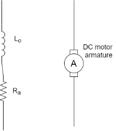
13) Since we can motel the DC motor armature as a series resistance and inductance, we can substitute the armature in place of the resistor and inductor in our DC switch circuit as shown in following figure.
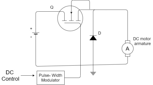
14) In figure pulse width modulator has been added. This is a subsystem that converts a DC control input vtg to a constant frequency variable duty cycle pulse train.
Q14) What is Variable speed [Variable frequency] AC motor drive.
A14)
1) If we wish to control the speed of an AC induction motor and produce rates torque throughout the speed range, we must vary the frequency of the applied voltage.
2) This sounds relatively simple. However, there is one underlying problem that affects this approach.
3) For induction motor as the following of the applied voltage decreases the magnetic flux increases.
4) Therefore, as the frequency is decreased, if the voltage is maintained constant, the core of the inductor will magnetically saturate (stator) and line curve will increase drastically, and it will overheat and fail.
5) In order to maintain a constant flux as we reduce the frequency, we must reduce the applied voltage by the same proportion.
6) This technique is commonly applied when operating a 60 Hz induction motor on a 50 Hz line
7) The motor will operate safely and efficiently if we reduce the 50Hz line voltage to 50/60 (or 83.3%) of motors rated vtg.
8) This principle applies to the operation of an induction motor at any frequency that is the ratio of the frequency 2-line vtg f/v must be maintained constant.
9) Therefore, if we wish to construct an electron; c system to produce a varying frequency to control the speed of the induction motor, it must also be capable of varying its output voltage proportional to output frequency.
Q15) Write PLC Applications in developing systems- Tank level controller using analog signals.
A15) Design a PLC program to control the liquid level in a tank. A level transmitter is used to measure the tank level into a standard current signal from 4 to 20mA as illustrated in the below process diagram.
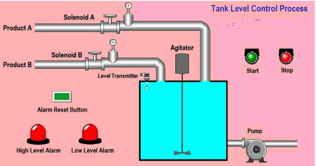
Program Logic
The agitator motor is to be started and stopped by a pushbutton station.
The solenoid valves are to be open (Energized) when the agitator is running.
Pump N0.1 starts at the 75% liquid level and stops at the 25% level. The pump will run only if the agitator is running.
On a high-level alarm (Tank 90%), an alarm light will come ON and stay on even if the tank level drops. An operator must press the reset button to turn off the light. On the high-level alarm, both the solenoid valve will also close (de-energize).
A low-level alarm light shall be provided (Tank 10%), similar to the high level, and reset using the same pushbutton.
Q16) Explain Temperature controller using RTD.
A16)
1. RTD devices with resistance that changes with temperature changes in a linear way.
2. This resistance value will change as temperature changes and by supplying a constant current, the measured voltage drop across the resistor can be used to determine the new resistance, and thus the temperature.
3. RTDs come in a variety of types, with the most common type is a PT100. It’s made from platinum that has been calibrated to be 100 ohms at 0 degrees C.
4. In above application, we want to measure material temperature of the tank, for that we use RTD sensor which will measure temperature of the tank and give signal to the temperature controller.
5. Temperature controller will send signal in the form of voltage (0-10V DC). If RTD detect 0degree temperature, it will send 0V DC and if maximum temperature detected, it will send 10V DC to PLC.
6. Temperature controller is directly connected to the PLC so PLC will read voltage.
7. Note: – Here we consider simple application for explanation. We need to measure material temperature of the tank by using RTD sensor. And also consider other components for control purpose.
8. Assume Scaling range of temperature controller is 0-100°C=0 to 10V DC and according to this signal PLC consider 0 to 27648.
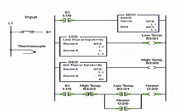
9. ON/OFF Control system is a commonly used method to control temperature. Comparison instructions, that are Less than or equal and Greater than or equal are set to control the temperature range.
10. A Less than or equal logic energize when the input value is less than or equal to the set point.
11. A Greater than or equal logic energize when the input value is greater than or equal to the set point
12. S1 connected in the first line and the last line of the above ladder diagram is programmed to the heater output circuit to control the circuit.
13. MOV instruction carries and displays the output values of the temperature measuring device, MOV instruction addresses a thermocouple here.
14. All the MOV, LEQ, GEQ are addressed to the same integer file.
15. Source A in both LEQ and GEQ are the thermocouple current output, which is compared with the setpoint value at the source B.
16. Setpoint for LEQ will be the lower range value and for GEQ it is the upper range value.
Now, look at the ladder diagram above
1. If source A < source B of the LEQ logic, then the low temp and heater output becomes TRUE.
The heater remains to ON as long as these two conditions satisfies - Low temp output is TRUE and High temp output is FALSE.
2. Even if the Low temp output turns FALSE the heating continues until the High temp turns TRUE.
Look at the latch in the last line of the ladder diagram.
3. The heater continues to be ON until the temperature reaches the upper range value.
4. When the temperature reaches higher range value, the source A will be equal to source B of the GEQ logic. Then the High temp becomes TRUE.
5. The heater turns OFF when the High temp becomes TRUE.
6. The heater remains OFF until the temperature reaches the lower range value. And starts again.
Q17) What is Speed control of electric motor?
A17)
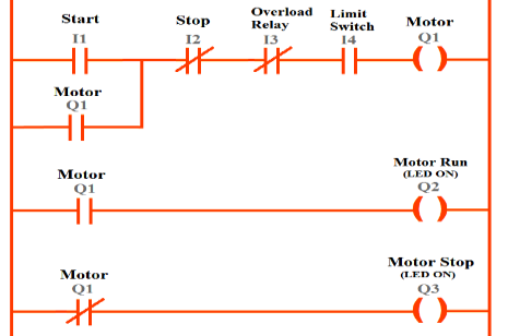
Start Button I1:
Normally open contact (Make contact) is used because the motor should only start when the button is pressed.
Stop Button I2:
Normally close (break contact) contact is used because the button should normally be closed or high so that the motor keeps on running. It should open when the button is pressed. It is opposite to start push button.
Overload relay I3:
In normal condition, this relay should allow the motor to rotate so normally close contact is selected for it. In case of overload it will stop the motor by opening its contact.
Limit switch I4:
The motor should only rotate when the limit switch is closed therefore normally open contact is used.
Output Q1, Q2, Q3:
Relay coil Q1, Q2 and Q3 represent motor output, motor indication ON and indication OFF respectively.
ON indicator gets input from normally open input which depends upon output Q1. OFF indicator is fed by normally close input which depends upon output Q2.
Input Q1 (for continuous rotation):
Since it is required that once push button is pressed, motor should run continuously even if the push button is released.
To achieve this part, an input Q1 (normally open) is used and connected in parallel with I1. This input depends upon output Q1.
When output is high, input Q1 is also high. Since input Q1 provides parallel path with I1, so if any of them is to be high, motor will run (if other conditions are also satisfied).
Start button (Normally open), stop button (Normally close), overload relay (Normally close) and limit switch (Normally open) are connected in series. So, motor will run if start button is pushed, stop button is not pressed, overload relay is not picked and limit switch is closed.