Unit –VI
SCADA Protocols
Q1) Explain Evolution of SCADA Protocols.
A1) In order for two or more entities to communicate, they must speak the same language (protocol) and adhere to certain rules for initiating, conducting, and ending the communication. This chapter reviews the most popular protocols for communicating information over networks such as the internet and explore proprietary and open protocol was designed specifically for use in SCADA systems.
Evolution of SCADA Protocols
SCADA protocols evolved out of the need to send and receive data and control information locally and over distances in deterministic time. Deterministic in this context refers to the ability to predict the amount of time required for a transaction to take place when all relevant factors are known and understood. To accomplish communication in deterministic time for applications in refineries, electric utilities and other users of SCADA systems, manufacturers of control devices, such as PLCs is, developed their own protocols and communication bus structure.
Table 3-1 summarizes some of these manufacturers and their corresponding protocols.
Table 6-1 SCADA Protocols
Manufacturer | Protocol |
Allen Bradley (Rockwell) | Device Net, Control Net, DF1, Data highway +, Data Highway 485 |
Siemens | Profibus |
Modicon | MODBUS, MODBUS plus, MODBUS TCP/IP |
Many of these protocols are proprietary. In the 1990s, control industry groups and standards organizations begin to develop open protocols for control systems that would be e non-proprietary and not exclusive to one manufacturer. Then, as the internet gained popularity, companies short to take advantage of the protocols and tools developed by the internet, such as the TCP/IP family of protocols and internet browsers. In addition, manufacturers and open standard organizations modified the highly popular and efficient Ethernet LAN technology for used in implementing data acquisition and control local area networks.
Background Technologies of the SCADA Protocols
In order for any entities to communicate, a protocol for that communication has to be established. A protocol defines the format of the messages and the rules for the exchange of the messages.
High level models are used to define where the protocols are applied and to compartmentalize the functions required to send and receive messages. The layered architecture model has been widely adopted and is very effective. In this model, the elements necessary for communication are divided into layers with defined interfaces between each layer. Two of the most widely used layered communication reference models are the open systems interconnection (OSI) model and the transmission control protocol/ Internet protocol (TCP/IP) model.
Q2) Explain Open systems interconnection (OSI) Model.
A2) Overview of the OSI Model
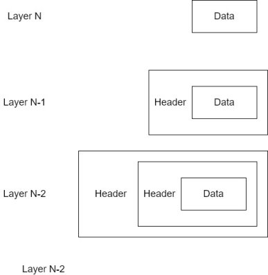
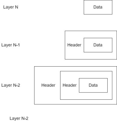
The open systems interconnection (OSI);reference model was developed by the International Standard Organization (ISO) in the beginning of the 1980s. In this model, the data from a higher level layer is encapsulated by the next lower layer as it is passed from higher to lower level layers. For example, a packet of data from a higher level will be encapsulated by the next lower layer by adding header information around the data packet. Figure 3-1 illustrates a basic encapsulated process.
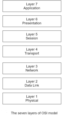
The OSI model layers are depicted in figure 6-2.
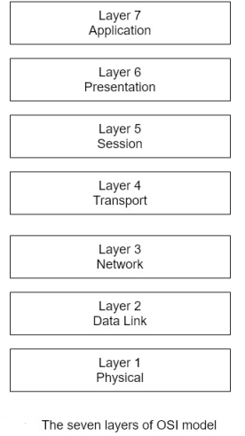
In the OSI model, the application layer, layer 7, is the interface of the user. Data traverses the model town word from layer 7 to layer 1, where a message packet is transmitted over a medium such as a wire or optical fiber cable as electrical or optical pulses, respectively. On the receiving end, the rivers procedure takes place, with the message packet transfer seeing the model from layer 1 up to layer 7.As previously discussed, the data is encapsulated as it travels down through the model layers at the transmitting node . At the receiving node, the encapsulated is stripped from the message as it works its way up to layer 7.
Table 6-2 summarizes the functions performed in each layer of the OSI model.
Table 6-2 Functions of OSI Model Layer
Layer | Functions |
7- Application | The application layer is the highest-level layer in the OSI model. It performs network flow control and application support functions. It confirms that the intended receiver (the target of the communication) is available. |
6- Presentation | The presentation layer performs conversions and translations for the application layer. It also performs encryption, decryption, and compression operations. For example, this layer translates data coded in the American Standard Code for Information Exchange(ASII) and the Extended Binary Coded Decimal Interchange Code (EBCDIC) |
5- Session | The session layer establishes and runs network sessions. Specifically, display establishes the desired communication connection, manages the data transmission during session, and releases the connection. The session layer supports simplex, half duplex and full duplex communications |
4- Transport | The transport layer is connection oriented in that it institutes of logical connection between the transmitting and receiving nodes. This layer establishes end-to-end integrity of the communication session and guarantees that the data will be delivered to the receiving host. |
3- Network | The network layer performs routing, addressing, error detection, and node traffic control. |
2- Data Link | The data link layer comprises to sublayers, the media access control (MAC) and logical link control sublayers and is responsible for free transmission of packets. This layer converts packets into bit form in preparation for transmission and manages the data frames between the physical and network layers. |
1-Physical | The physical layer connects the computer to the physical network transmission media. As such, it is responsible for converting the packet data to electrical signals for optical pulses and defines the electrical and mechanical interfaces to the network. EIA-232 and EIA - 422 specifications are examples of such standard interfaces. |
Each layer in the OSI model uses specific protocols to implement its functions. Table 6-3 provides example of some of the protocols associated with each layer.
Table 6-3 OSI Protocols
Layers | Protocols |
7- Application | FTP ( file transfer protocol): Supports transfer of files between computers. SMTP (simple mail transport protocol): Collects network information and presents it to network management consoles. |
6- Presentation | HTTP (hypertext transfer protocol) : The protocol used by the world wide web (WWW). HTTP is a stateless protocol in that it executes its commands without any knowledge of its private state and any previously executed commands. HTTP define sir formats for message transmission and how browsers react to instructions. IPEG (Joint Photographic Experts Group) : A defined standard for graphics. MPEG (Motion Pictures Experts Group) : Standard for coding and compression of motion picture video. |
5- Session | RPC (remote procedure call): In the client server model, a protocol that supports a request for service from one computer on a network from another computer on the network. NFS ( network file system) : Supports file sharing |
4- Transport | TCP ( Transmission Control Protocol): Provides stream oriented, reliable connections, error connections, and flow control, which prevent buffer overflow. UDP (User Datagram Protocol) : Unlike TCP, UDP does not perform error correction, UDP delivers messages on a best effort basis. |
3-Network | IP (Internet Protocol):Assigns IP addresses of the sender and recipient to data packets to be used in routing the messages to its intended receiver. IP does not guarantee reliable delivery of data packets. ICMP (Internet Control Message Protocol): A management protocol used to determine transmission routes from a source to a destination host and to check the availability of a host to receive messages. One of the ICMP utilities is PING, which is used to check the connection of host to the network. |
2- Data Link | ARP ( Address resolution protocol): Determines the MAC hardware address of a destination host from its IP address. PPP (Point-to-point protocol): A full duplex, encapsulation protocol for sending IP messages over point to point links. |
1-Physical | EIA-422-B (RS-422): Electronic Industries Association standard that defines the electrical characteristics of a balanced interface circuit that is designed for high common mode noise rejection and data rates less than 0.5 Mbps. EIA-232C (RS-232C): Electronic Industries Association standard for serial binary data exchange. |
Q3) Explain TCP/IP protocol.
A3) Overview of the TCP/IP Model
The transmission control protocol/ Internet protocol (TCP/IP) was developed in the 1970s by the U.S. Department of Defense to implement reliable network communications. TCP/IP powers the internet and internet's various capabilities are based on TCP/ IP protocols.
The OSI model was developed after TCP/ IP, but it attempted to maintain some similarities to the TCP /IP model. The four TCP/ IP layers are illustrated in figure 6-3 and their functions are given in table 6-4.
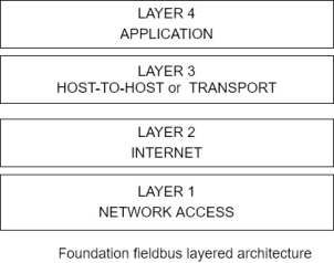
Figure 6-3 The TCP/IP layered architecture
Table 6-4 Functions of TCP/IP Model Layers
Layer | Function |
4- Application | As in the OSI model layer 7, the application layer is the interface to the user. It supports the user network application and performs flow control and error recovery. |
3- Host-to-Host or Transport | The host to host layer assembles data in packets provides for connection-oriented end-to-end communication, support error free and reliable delivery of message packets and control the network data flow. |
2- Internet | The internet layer performs routing and addressing. |
1-Network Access | The network access layer includes the functions of the data link and physical layers of the OSI model. It converts packets into bits for transmission over the physical medium and is responsible for error free delivery of frames. |
The TCP/ IP layers also incorporates protocols to perform the layers functions. Examples of these protocols are listed in table.
Table 6-5 TCP/IP
Layer | Protocols |
4-Application | FTP (File transfer protocol): Supports transfer of files between computers. SMTP (Simple mail transport protocol) : Support v the sending and receiving of email messages. SNMP (Simple Network management protocol): collects network information and presents it to network management consoles. Telnet: using terminal emulation, telnet provides a client with the capability to access a remote computer. |
3- Host-to-Host or Transport | TCP ( Transmission control protocol): Provides stream oriented, reliable connection error connection, and flow control, which prevent buffer overflows. UDP ( user datagram protocol): Unlike TCP, UDP does not perform error connection and delivers messages on a best effort basis. |
2- Internet | IP (Internet protocol): Assigns IP addresses of the center and recipient to data packets to be used in routing the message to its intended receiver. IP does not guarantee reliable delivery of data packets. ICMP ( Internet Control Message Protocol): A management protocol used to determine transmission routes from a source to the destination host and to check the availability of host to receive messages. One of the ICMP utilities is PING, which is used to check the connection of host to the network. |
2- Internet | ARP (Address resolution protocol): Determines the MAC hardware address of a destination host from its IP address. PPP ( Point-to-point protocol): A full duplex, encapsulation protocol for sending IP messages over point-to-point links. |
1-Network Access | IEEE 802.2 Logical Link Control: Manages data link communications between devices and performs error checking on frames received. EIA-422-B (RS-422): Electronic Industries Association standard that defines the electrical characteristics of a balanced interface circuit that is designed to for high common mode noise rejection and data rates less than 0.5 Mbps. EIA-232C (RS-232C): Electronic Industries Association standard for serial binary data exchange. |
Using this background on the layered models and associated protocols, we can now explore the related SCADA models and protocols in the following sections.
SCADA Protocols
The SCADA system protocols evolved from proprietary hardware and software design specially for SCADA systems point the protocols were developed out of necessity to serve the burgeoning market for computer applications in real time control situations. Then, it is an effort to take advantage of new networking developments, SCADA protocols incorporated versions of Internet and Local area network technologies. This move lead to some standardization, but also exposed SCADA systems to attacks commonly used against these technologies in IT environments.
Q4) Explain The MODBUS Model.
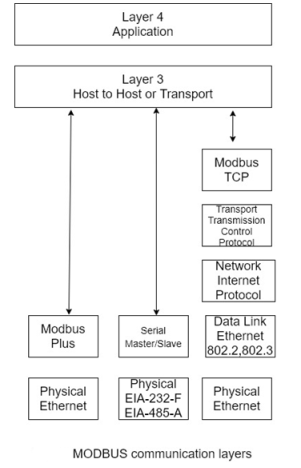
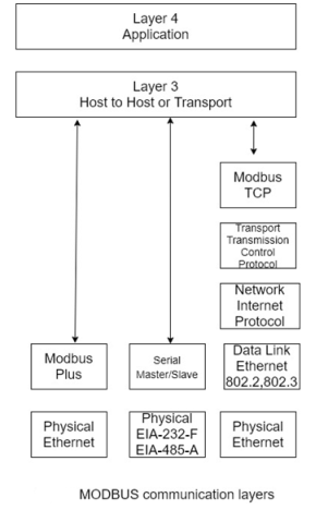
A4) In the late 1970s, Modicon, Incorporated, developed the MODBUS protocol. MODBUS is positioned in layer 7 (the application layer of the OSI model) and supports client-server communications among Modicon PLCs and another networked device. The MODBUS protocol defines the methods for a PLC to obtain access to another PLC, for a PLC to respond to other devices, and means for detecting and reporting errors. The protocol supports other protocols such as asynchronous master slave transmission, Modicon MODBUS Plus, and Ethernet. To take advantage of the supporting tools, hardware, and software that are used for the internet, MODBUS/TCP was also developed. It too is based on the OSI model, although not all layers are used. The communications layer of various MODBUS protocol implementations is given in figure.
Atypical MODBUS transaction comprises the following steps:
1) The MODBUS Application protocol sets the format of a client-initiated request.
2) Function code in a MODBUS data unit, as the message packet is called, directs the server to execute a specific action.
3) Data field in the message provides additional information used by the server to perform the requested action.
4) If there are no errors in the exchange, the server completes the requested action, typically sending data back to the client.
5) If an error occurs, the server needs an exception code in the data unit to determine the next action to be performed.
Q5) Explain The DNP3 Protocol.
A5) DNP3 is an open SCADA protocol that is used for serial or IP communication between control devices. It is widely used by utilities such as water companies and electricity suppliers for the exchange of data and control instructions between master control stations and remote computers or controllers called outstations. Typical commands issued by the master control station are “open a valve”, and “provide data on a particular control station.” The master control station might also provide analogue output signals to the outstation.
An outstation provides the master control station with information such as pressures, status of a circuit breaker or re-closer, analogue signals representing such items as temperature or power and information files.
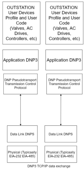
DNP3 has also adapted to Internet technologies by using TCP /IP for exchange of DNP3 messages. A typical DNP3 TCP/ IP layered architecture showing the exchange of data between a master control station and outstation is given in figure.
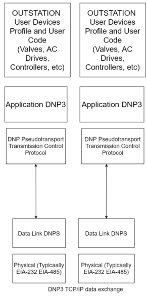
A DNP3 comprises a header and data. The header comprises the following
- DNP3 source device address
- DNP3 destination device address
- Frame size
- Data link control information
The data portion of the header contains the data that traverses the layers from the highest to the lowest layer.
Q6) What are UCA 2.0 and IEC61850 Standards. Explain.
A6) In the early 1990s, the Electric Power Research Institute (EPRI) decided that an effort was needed to define a more robust standard than DNP3 b to serve the SCADA needs of the electric utilities. The result was the Utility Communications Architecture (UCA). UCA version 2.0 is a family of communications protocols aimed at meeting the needs of electric utilities. UCA 2.0 is based on the Manufacturing Messages Specification (MMS) from ISO Standards ISO 9506-1:2000 and ISO 9506-2:2000. In 1999, UCA 2.0 migrated to IEC Standards IEC61850 for substation automation. IEC61850 is part of a Common Information Model (CIM) developed by IEC Technical Committee 57 that also includes the following standards:
- IEC61970: Power systems and programming interfaces for integrating utility applications
- IEC61968: Distribution equipment and processes
- IEC60870-5: Distribution
- IEC60870-6: Transmission
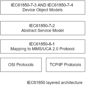
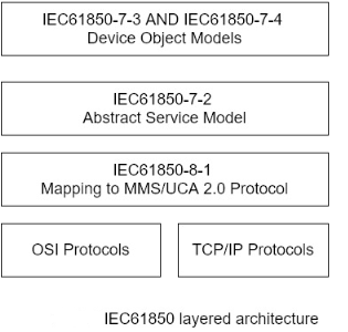
IEC61850 is a layered architecture standard that separates the functionality required for electric utility applications from the lower level networking tasks. The layered architecture illustrating the separation of functions is shown in figure.
Controller Area Network
Controller area network (CAN) protocols (ISO Standards 11898-1) word developed for the automotive industry by Robert Bosch, GMBH, in the mid-1980s for use in serial communications up to 1 Mbps. CAN supports up to 110 nodes on a two wires, half duplex network.
The protocols operate at layer 1, the physical layer, and layer 2, data link layer, of the OSI model.
CAN communications are based on the Ethernet carrier sense multiple access with collision detection (CSMA/CD) method. With CSMA/CD, multiple devices compete to transmit information over a common bus point when a device sensors that the buses free (no carrier signal on the bus), it tries to transmit over the bus. In the event and other device tries to communicate over the bus at the same time, the device detects the collision, back off, and try again at a random time later. Thus, with this approach, specific transmission across the network cannot be guaranteed. To compensate for this situation, CAN provides transmission priorities to nodes using the CSMA/CD+AMP (arbitration on message priority) scheme. CSMA/CD +AMP employs a unique identifier that includes a priority rating in a message instead of the source and destination node addresses as used in the conventional CSMA/CD arbitration method. The lower the value of the identifier, the higher the priority that is assigned to the message find the length of this identifier varies, being 11 bits in the identifier priority value, the CAN transmission algorithm involves the following steps:
1. A message with the highest priority identifier is granted access to transmit.
2. Each node transport by a message examines the unique identifier to determine whether the message is being sent to that node.
3. If a message is intended for that node, the node processes the message. Messages with a lower priority identifier are transmitted after higher priority messages according to their identifier values.
Q7) Explain Control and Information Protocol.
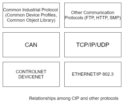
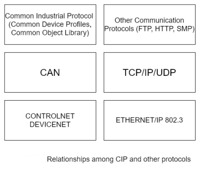
A7) The Common Industrial Protocol (CIP) is an open family of protocols that is implemented in the application, presentation, and session layers of the OSI model. Thus, CIP forms a common upper layer of protocols that can be used above different lower layers, such as those employing Ethernet/IP, Device Net, and ControlNet, all of which are discussed in following sections. It also includes a messaging protocol that supports explicit messaging and input output, CIP is maintained by ControlNet International (CI) and the Open Device Net Vendor Association (ODVA).
The value of CIP is that it makes pre-defined objects and communication standards available to the lower layers of the OSI model. CIP comprises communication objects, which are used to define maximum data values, type and characteristics of the connection, and timing of the connection. It also supplies 46 – class object library, which includes control supervisor objects, what objects identity objects, analogue output. Objects, parameter objects, discrete input objects, position sensor objects and AC/ DC drive objects.
The among CIP, CAN, and other protocols are illustrated in figure.
Q8) Exlain the following:
- Device Net
- Control Net
- Ethernet/IP
A8)
1. Device Net
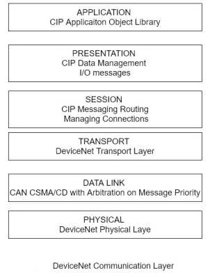
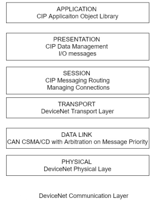
Device Net is an open standard that is used to connect equipment’s such as motor starters, census, valve controls, displays, operator interfaces, and higher-level control computers and PLCs. Device Net is based on the CAN protocols dot it also uses the CIP family of protocols, including its object libraries and object profiles for configuration and control of the equipment and to obtain data from the local devices through the CAN protocols at the data link and physical layers. In order to cash and information exchange, for example, Device Net establishes a connection instance using an identity object, a message ruta object, a Device Net object, and connection object. The Identity object contains information such as the device profile, division number and vendor information point the message Sutra object rules messages to the proper destination and the Device Net Device Net information such as the MAC identification number point the connection object manages the messaging connection. Device Net supports communication rates of 125 kbps to 50 kbps and 500kbps for up to 64 nodes.
Figure illustrates the Device Net layers and their use with CIP.
2. ControlNet
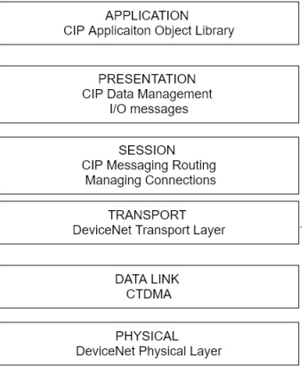
ControlNet is an open network for use in real time, deterministic SCADA applications. It also uses the CIP protocol object capability and can support up to 99 notes on the network at a data rate of 5 Mbps.it is designed for applications that comprise multiple controllers and operator interfaces and its supports exchange of real-time input output data as well as messaging information.
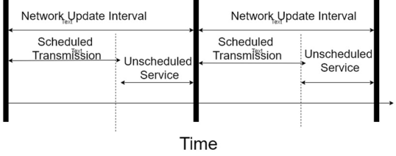
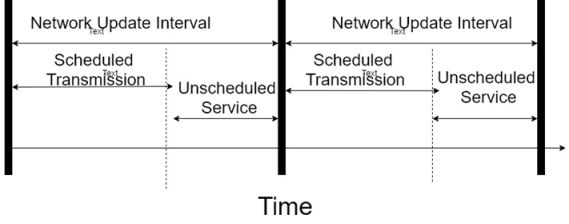
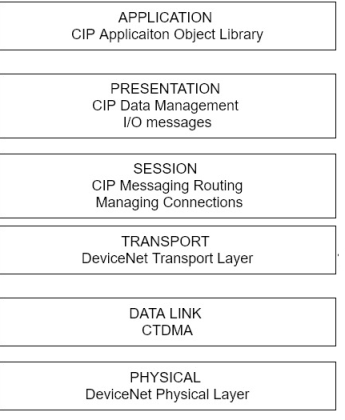
The determinism of Control net comes from the incorporation of the Concurrent Time Domain Multiple Access (CTDMA) algorithm that allows on load on the network to transmit at a specified interval cause the network update time or NUT. Thus, critical information is transmitted during a NUT interval while noncritical information is sent in unscheduled periods, as they are available.
3. Ethernet/IP
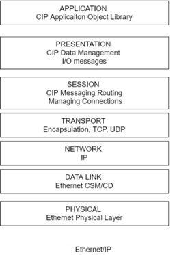
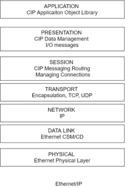
Ethernet/IP also applies CIP by encoding CIP messages in Ethernet frames. In addition to the basic CIP object classes, Ethernet/IP uses a TCP/IP object for implementing the TCP/IP protocol and un Ethernet link object comprising parameters for establishing an Ethernet/IP link. CIP operates at the application layer providing the application object library, at the presentation there providing messaging services, and at the session player supporting messages routing and connection management. The session layer interfaces to the transport and network layers which performs encapsulation and apply either the TCP or the UDP protocol at the transport layer and the IP protocol at the network layer. The data completes the downward transition at the data link layer, which implements CSMA/CD Ethernet physical layer, which connects to the transmission medium.
Because the Ethernet uses CSMA/CD, which operates by detecting collisions, backing off, and trying to resend at random intervals, complications and not deterministic. This situation poses problems for real time data acquisition and control point in order to mitigate this situation, Ethernet/IP applies layer 2 switches to partition collision domains into single nodes or small groups point the division significantly reduces CSMA/CD collisions. Also, advances in Ethernet technology, especially fast Ethernet (100 Mbps) and Gigabyte internet (10 Mbps), drastically reduced the non-deterministic communication latency times.
Third mitigation factor is the availability of the user datagram protocol (UDP), which transmits packets on a best effort basis and does not carry the overhead associated with TCP transmission, which confirms the communication connection and checks for errors in transmission.
Finally, the IEEE developed the 802. 1P specification for prioritizing network traffic by incorporating a 3-4 with header field that prioritizes messages and allows for the grouping of packets into different priority traffic classes. Figure shows the Ethernet /IP layers and their relationship to CIP.
Q9) What is FFB? Explain.
A9) The flexible function block (FFB) process is a control half-duplex bus network. It was developed by the Fieldbus Foundation, which is a consortium of 1:30 automation organizations. The goal of the consortium was to develop an open, to wear International standard for process automation applications. It is particularly useful for controlling devices such as valves and transmitter devices.
In operation, each device on FFB network taps into the two-wire bus structure. Logically, FFB operates as a 31.25 kbps master slave network, but functions for a brief period as a token passing scheme. In the master slave communication model, a master of primary device controls a number of slave of secondary devices. The master sends control signals to the slave devices and they respond according to the control instructions received. The slaves can send information back to the master for storage, interpretation, and processing. The token passing scheme is a method used to arbitrate among devices that desire to communicate on a network. Unlike the CSMD/CD approach where collision can occur when devices try to send messages at the same time, in a token passing network, only one device at a time can transmit.
A device can transmit when it receives an electronic token like a message that is passed around. There is only one token on the network and, when a mission is complete or if the device does not need to transmit, the token is passed on to the next device. Then, the next device can transmit. This process continuous and token is passed around the network.
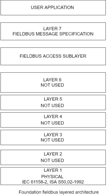
Relative to the OSI model, FFB incorporates a user application layer, a fieldbus message specification layer, fieldbus access sublayer, data link layer, and a physical layer. Layer 3 through 6 of the corresponding OSI model are not used. The FFB layers are shown in figure 3-12.
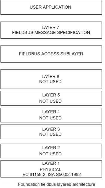
In the FFB layer, the application layer comprises the Fieldbus Message Specification (FMS) and the Fieldbus Access Sublayer (FAS). FMS provides for the exchange of messages among applications and FAS supports the FMS. The data link layer uses a link active scheduler (LAS); to control the sending of fieldbus messages. The LAS is the mechanism that FFB uses to provide determinism by maintaining a list of network transmission times for all devices on the network. Devices transmit at their designated transmit times and, if there is time available between these scheduled transmit X, devices can transmit during this unscheduled time. The FFB physical layer follows IEC Standard 61158-2 and ISA Standard 550.02-1992. The electrical characteristics of this year include the use of Manchester bi phase encoding of the digital signals and a 10-mA current loop. Manchester encoding uses pulse transmission 2 to represent binary ones and zeros instead of pulse voltage or current levels. The FFB physical layer also provides power supply voltages from 9 to 32 volts.
Q10) Explain Profibus and their versions.
A10)
- Profibus
Profibus (Process Fieldbus) is an open field bus serial network standard for use in time critical control and data acquisition application. It falls under the European International fieldbus standard, EN 50 170, add defines the functional, electrical, and mechanical characteristics of a serial fieldbus. Profibus is similar to the foundation fieldbus but provides transmission rates of 31.25 kbps. 1 Mbps, and 2.5 Mbps in the physical layer.
Because Profibus is an open standard, it can accommodate devices from different manufacturers. Profibus resides at the application, data link and physical layers of the OSI model. It provides determinism for real time control applications and supports multi master and master slave communication networks. There are three versions of Profibus, which are summarized in the following list:
- Profibus Factory Automation (Decentralized Peripherals (DP)-
Provides high-speed communication between control systems and decentralized control devices. It uses different physical layer standards than those employed by Profibus PA. Optional and upward compatible extensions have been added to Profibus DP. The extended version is denoted as Profibus- DPV1 and includes diagnostics, alarming messaging, and parameterization.
- Profibus Fieldbus Message Specification (FMS):
Developed to support a large number of applications and higher-level network interconnections among applications at average transmission rates. It offers a large selection of functions and is generally more complicated to implement than Profibus PA or Profibus DP. The three Profibus versions with their primary characteristics are given in figure 6-13.
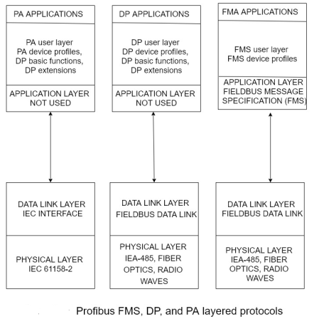
Figure 6-14 illustrates the communication architectures of the profitable versions and shows their relationship in the OSI seven-layer model.

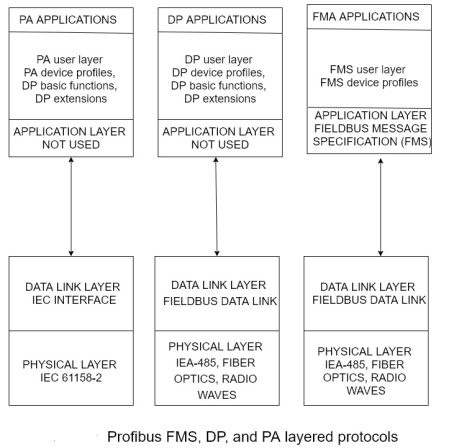
In figure, the physical layers use either the EIA-485 standard for the IEC 61158-2 standard. If desired, all three Profibus versions can use the same bus line if their employ EIA-485 in the physical layer. However, if the application requires intrinsically safe circuitry, IEC 61158-2 must be used. IEC -485 provides transmission rates of 9.62 to 1200 kbps while IEC 61158-2 operates at 31.25 kbps.
Q11) What are The security implications of the SCADA Protocol?
A11) The security implications of the SCADA Protocol
Most networks, including SCADA networks, have some common security issues and corresponding controls. And important consideration for SCADA networks is that they cannot afford nondeterministic delays, security mechanism that require large memory capacities, locking out of operators, and relative Lee long processing tines. However, some of the fundamental security measures available to SCADA systems are like those used for OSI and TCP/IP layered architectures. Network best practices include protecting the confidentiality, integrity, availability (CIA) of the data and long with providing non-repudiation authentication and access services.
Q12) Explain different types of firewalls.
A12) Firewalls
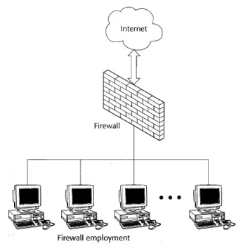
Ok security elements of protection that is required of any network connected to an untrusted network, such as the internet, is a firewall. A firewall provides protection against virus’s worms, and other types of malicious code as well as from Network intrusions. An issue with firewalls applied to SCADA protocols. This situation is being researched by a number of organizations and some SCADA aware firewalls are under development.
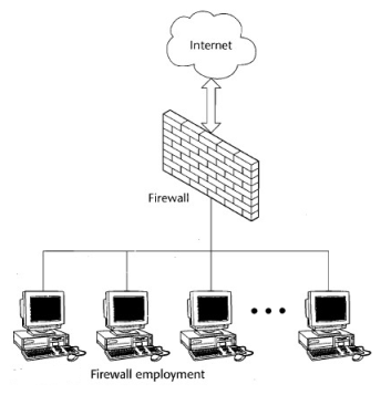
A typical network configuration employing a firewall between and internal LAN and Internet is given in figure 3-15.
The three common types of firewalls are packet filtering firewall, stateful inspection firewalls, and proxy firewalls.
1.Packet- Filtering Firewalls
A packet filtering firewall operates at layer 3, the network layer, of the OSI model and uses filtering criteria to decide whether to permit or deny packets entry into the Local Network. The parts of the packet that are examined are the source IP address, the destination IP address, and internet protocols carried by the packet.
By checking the source IP address of the incoming packet, a packet filtering firewall can block packets from unwanted IP sources, such as untrusted hosts, advertisers, and spam mailers. The filtering is based on database files known as access control lists (ACLs) that are stored by the firewall.
By using similar sets of rules, a packet filtering firewall can prohibit traffic from being sent to an internet IP destination address. This action can prevent messages from being sent to computers containing highly classified information and reduce the number of messages sent to specific hosts.
Third filter is based on examining the Internet protocol carried by the packet. Some of the protocols that are examined are normal internet protocol (IP), address resolution protocol (ARP), reverse address resolution protocol (RARP), transmission control protocol (TCP), user datagram protocol (UDP), and the Internet control message protocol (ICMP). The firewall can block packets with specific protocols from entering the trusted network.
2. Stateful Inspection Firewalls
A stateful inspection firewall stores and maintains information from an incoming packet in a dynamic memory state table. These tables stored the source and destination connection information associated with the packet and use rules to determine if the communication should be allowed to proceed. Connection information includes the destination address and pot and the source address and port. Because the speed of operation of a stateful inspection firewall is determined by the time it takes to perform a more detailed examination of the packet state and the number of connections handle, queuing delays might occurred that would be detrimental to the operation of a SCADA system.
3. Proxy Firewalls
Proxy or application layer firewalls operate at layer 7 of the OSI model. In the dictionary, A proxy is defined as a person authorized to act for another, an agent or substitute. Thus, proxy software can be e placed between a user and a server to conceal the identity of the user. The server sees proxy and cannot identify the user. The scenario is also true in the rivers situation where the user interacts with the proxy software in front of the server and cannot identify the server or its associated network. A proxy firewall is effective in shielding a network from an untrusted outside network, such as the Internet.
Q13) What is demilitarized zone? Explain their types in brief.
A13) Demilitarized Zone
Firewalls can be used to implement security network architectures that are effective for SCADA systems. These architectures are based on the concept of a demilitarized zone or DMZ. A DMZ is a region that provides a separation between an external or public Network and an internal or private network. In order for a firewall to support a DMZ, it must have multiple external interfaces and corresponding access control lists, where necessary. Several different architectures used DMZs, but there are two that are particularly applicable to data acquisition and control environments. These architectures are a single firewall DMZ and a dual firewall DMZ. They can serve the purpose of separating a corporate enterprise network from the control network while providing a connection for both to a public network such as Internet.
Single Firewall DMZ
In a single firewall DMZ, a firewall is used to filter data packets from, for example, an enterprise network to the local control network and from an external network. The DMZ contains the elements that have to be accessed by the enterprises computers as well as the connection to the outside, public network. This architecture is shown in figure 3-16.
Because there is no firewall between DMZ and control network, the control network is potentially vulnerable if the DMZ is penetrated by an attack from the external network for through the enterprise network.
Dual Firewall DMZ
The security of a SCADA network can be increased by adding a second firewall between the control network and the DMZ . This arrangement implements dual firewall DMZ. See figure 3-17.
Q14) What are the general Firewall Rules for Different Services?
A14) General Firewall Rules for Different Services
Because of the stringent requirements of SCADA systems with regard to timing, availability, and data processing, Firewall rules have to be tailored for the various protocols and network services. The Industrial Automation Open Networking Association (IAONA) developed protocol guidelines. (The IAONA Handbook for Network Security – Draft/RFC version 0.4, Magdeburg, Germany,2003) for network services that accommodate the unique SCADA system characteristics. These guidelines for communications with SCADA systems are summarized in table 3-6. The services provided by the protocols are summarized in table 3-3 and 3-5.
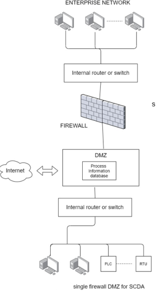
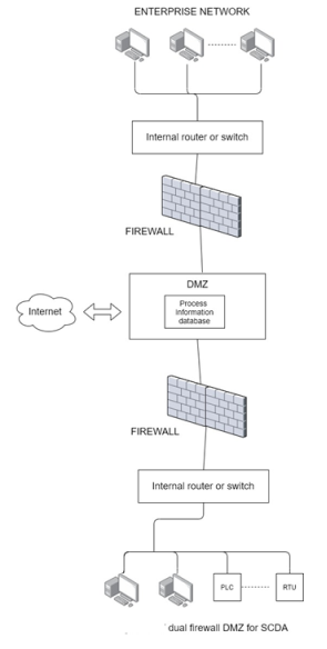
Table 6-6 Firewall Protocol Rules for Different Services to SCADA Systems
Protocol | Rule |
File Transfer protocol (FTP) | FTP permitted on outbound communications only. Should employ an encrypted VPN tunnel and token based two factor authentication. Inbound communications not permitted. |
Trivial File Transfer protocol (TFTP) | TFTP should not be permitted |
Simple Mail Transfer protocol (SMTP) | Outbound email messages permitted; inbound email messages blocked |
Telnet | Outbound communications should employ an encrypted VPN tunnel to known devices inbound communications should employ an encrypted VPN tunnel and token based two factor authentication. |
Hypertext Transfer Protocol (HTTP) | Inbound communications should not be permitted unless necessary. If required, http should be used with the secure sockets layer (SSL) Protocol (HTTP/S). SSL provides encryption and authentication capabilities. Communications from the enterprise should be configured in the firewall to block Java and other scripts. |
Simple Network Management Protocol (SNMP) | SNMP communications should not be permitted unless implemented over a different, secure network. |
SCADA and Industrial Protocol | Because security was not considered in the design of these protocols, communications should be prohibited to and from the enterprise Network and limited to the process control networks and related process control information networks. |
Q15) What is Virtual Private Network?
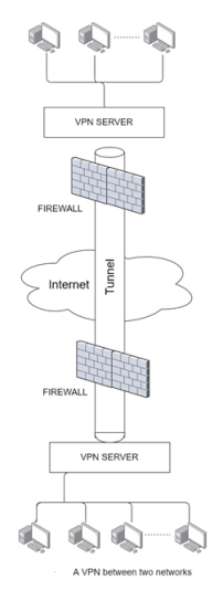
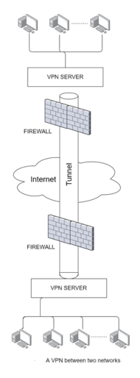
A15) A virtual private network or VPN is a highly effective solution for transmitting data security over the internet or a wide area network. A VPN is said to create a secure tunnel in an untrusted Network and through a Firewall, through which sensitive data can be transmitted.
The Tunnel is created by encapsulating, or by encapsulating and encrypting, the data and then transmitting it over the network. Typically, data is encapsulated by adding a header and then encrypted before being transmitted. A VPN securely connecting two networks is illustrated in figure 3-18.
Unit –VI
SCADA Protocols
Q1) Explain Evolution of SCADA Protocols.
A1) In order for two or more entities to communicate, they must speak the same language (protocol) and adhere to certain rules for initiating, conducting, and ending the communication. This chapter reviews the most popular protocols for communicating information over networks such as the internet and explore proprietary and open protocol was designed specifically for use in SCADA systems.
Evolution of SCADA Protocols
SCADA protocols evolved out of the need to send and receive data and control information locally and over distances in deterministic time. Deterministic in this context refers to the ability to predict the amount of time required for a transaction to take place when all relevant factors are known and understood. To accomplish communication in deterministic time for applications in refineries, electric utilities and other users of SCADA systems, manufacturers of control devices, such as PLCs is, developed their own protocols and communication bus structure.
Table 3-1 summarizes some of these manufacturers and their corresponding protocols.
Table 6-1 SCADA Protocols
Manufacturer | Protocol |
Allen Bradley (Rockwell) | Device Net, Control Net, DF1, Data highway +, Data Highway 485 |
Siemens | Profibus |
Modicon | MODBUS, MODBUS plus, MODBUS TCP/IP |
Many of these protocols are proprietary. In the 1990s, control industry groups and standards organizations begin to develop open protocols for control systems that would be e non-proprietary and not exclusive to one manufacturer. Then, as the internet gained popularity, companies short to take advantage of the protocols and tools developed by the internet, such as the TCP/IP family of protocols and internet browsers. In addition, manufacturers and open standard organizations modified the highly popular and efficient Ethernet LAN technology for used in implementing data acquisition and control local area networks.
Background Technologies of the SCADA Protocols
In order for any entities to communicate, a protocol for that communication has to be established. A protocol defines the format of the messages and the rules for the exchange of the messages.
High level models are used to define where the protocols are applied and to compartmentalize the functions required to send and receive messages. The layered architecture model has been widely adopted and is very effective. In this model, the elements necessary for communication are divided into layers with defined interfaces between each layer. Two of the most widely used layered communication reference models are the open systems interconnection (OSI) model and the transmission control protocol/ Internet protocol (TCP/IP) model.
Q2) Explain Open systems interconnection (OSI) Model.
A2) Overview of the OSI Model
The open systems interconnection (OSI);reference model was developed by the International Standard Organization (ISO) in the beginning of the 1980s. In this model, the data from a higher level layer is encapsulated by the next lower layer as it is passed from higher to lower level layers. For example, a packet of data from a higher level will be encapsulated by the next lower layer by adding header information around the data packet. Figure 3-1 illustrates a basic encapsulated process.
The OSI model layers are depicted in figure 6-2.
In the OSI model, the application layer, layer 7, is the interface of the user. Data traverses the model town word from layer 7 to layer 1, where a message packet is transmitted over a medium such as a wire or optical fiber cable as electrical or optical pulses, respectively. On the receiving end, the rivers procedure takes place, with the message packet transfer seeing the model from layer 1 up to layer 7.As previously discussed, the data is encapsulated as it travels down through the model layers at the transmitting node . At the receiving node, the encapsulated is stripped from the message as it works its way up to layer 7.
Table 6-2 summarizes the functions performed in each layer of the OSI model.
Table 6-2 Functions of OSI Model Layer
Layer | Functions |
7- Application | The application layer is the highest-level layer in the OSI model. It performs network flow control and application support functions. It confirms that the intended receiver (the target of the communication) is available. |
6- Presentation | The presentation layer performs conversions and translations for the application layer. It also performs encryption, decryption, and compression operations. For example, this layer translates data coded in the American Standard Code for Information Exchange(ASII) and the Extended Binary Coded Decimal Interchange Code (EBCDIC) |
5- Session | The session layer establishes and runs network sessions. Specifically, display establishes the desired communication connection, manages the data transmission during session, and releases the connection. The session layer supports simplex, half duplex and full duplex communications |
4- Transport | The transport layer is connection oriented in that it institutes of logical connection between the transmitting and receiving nodes. This layer establishes end-to-end integrity of the communication session and guarantees that the data will be delivered to the receiving host. |
3- Network | The network layer performs routing, addressing, error detection, and node traffic control. |
2- Data Link | The data link layer comprises to sublayers, the media access control (MAC) and logical link control sublayers and is responsible for free transmission of packets. This layer converts packets into bit form in preparation for transmission and manages the data frames between the physical and network layers. |
1-Physical | The physical layer connects the computer to the physical network transmission media. As such, it is responsible for converting the packet data to electrical signals for optical pulses and defines the electrical and mechanical interfaces to the network. EIA-232 and EIA - 422 specifications are examples of such standard interfaces. |
Each layer in the OSI model uses specific protocols to implement its functions. Table 6-3 provides example of some of the protocols associated with each layer.
Table 6-3 OSI Protocols
Layers | Protocols |
7- Application | FTP ( file transfer protocol): Supports transfer of files between computers. SMTP (simple mail transport protocol): Collects network information and presents it to network management consoles. |
6- Presentation | HTTP (hypertext transfer protocol) : The protocol used by the world wide web (WWW). HTTP is a stateless protocol in that it executes its commands without any knowledge of its private state and any previously executed commands. HTTP define sir formats for message transmission and how browsers react to instructions. IPEG (Joint Photographic Experts Group) : A defined standard for graphics. MPEG (Motion Pictures Experts Group) : Standard for coding and compression of motion picture video. |
5- Session | RPC (remote procedure call): In the client server model, a protocol that supports a request for service from one computer on a network from another computer on the network. NFS ( network file system) : Supports file sharing |
4- Transport | TCP ( Transmission Control Protocol): Provides stream oriented, reliable connections, error connections, and flow control, which prevent buffer overflow. UDP (User Datagram Protocol) : Unlike TCP, UDP does not perform error correction, UDP delivers messages on a best effort basis. |
3-Network | IP (Internet Protocol):Assigns IP addresses of the sender and recipient to data packets to be used in routing the messages to its intended receiver. IP does not guarantee reliable delivery of data packets. ICMP (Internet Control Message Protocol): A management protocol used to determine transmission routes from a source to a destination host and to check the availability of a host to receive messages. One of the ICMP utilities is PING, which is used to check the connection of host to the network. |
2- Data Link | ARP ( Address resolution protocol): Determines the MAC hardware address of a destination host from its IP address. PPP (Point-to-point protocol): A full duplex, encapsulation protocol for sending IP messages over point to point links. |
1-Physical | EIA-422-B (RS-422): Electronic Industries Association standard that defines the electrical characteristics of a balanced interface circuit that is designed for high common mode noise rejection and data rates less than 0.5 Mbps. EIA-232C (RS-232C): Electronic Industries Association standard for serial binary data exchange. |
Q3) Explain TCP/IP protocol.
A3) Overview of the TCP/IP Model
The transmission control protocol/ Internet protocol (TCP/IP) was developed in the 1970s by the U.S. Department of Defense to implement reliable network communications. TCP/IP powers the internet and internet's various capabilities are based on TCP/ IP protocols.
The OSI model was developed after TCP/ IP, but it attempted to maintain some similarities to the TCP /IP model. The four TCP/ IP layers are illustrated in figure 6-3 and their functions are given in table 6-4.
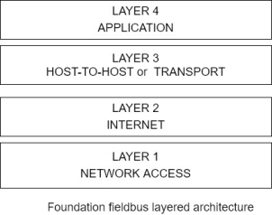
Figure 6-3 The TCP/IP layered architecture
Table 6-4 Functions of TCP/IP Model Layers
Layer | Function |
4- Application | As in the OSI model layer 7, the application layer is the interface to the user. It supports the user network application and performs flow control and error recovery. |
3- Host-to-Host or Transport | The host to host layer assembles data in packets provides for connection-oriented end-to-end communication, support error free and reliable delivery of message packets and control the network data flow. |
2- Internet | The internet layer performs routing and addressing. |
1-Network Access | The network access layer includes the functions of the data link and physical layers of the OSI model. It converts packets into bits for transmission over the physical medium and is responsible for error free delivery of frames. |
The TCP/ IP layers also incorporates protocols to perform the layers functions. Examples of these protocols are listed in table.
Table 6-5 TCP/IP
Layer | Protocols |
4-Application | FTP (File transfer protocol): Supports transfer of files between computers. SMTP (Simple mail transport protocol) : Support v the sending and receiving of email messages. SNMP (Simple Network management protocol): collects network information and presents it to network management consoles. Telnet: using terminal emulation, telnet provides a client with the capability to access a remote computer. |
3- Host-to-Host or Transport | TCP ( Transmission control protocol): Provides stream oriented, reliable connection error connection, and flow control, which prevent buffer overflows. UDP ( user datagram protocol): Unlike TCP, UDP does not perform error connection and delivers messages on a best effort basis. |
2- Internet | IP (Internet protocol): Assigns IP addresses of the center and recipient to data packets to be used in routing the message to its intended receiver. IP does not guarantee reliable delivery of data packets. ICMP ( Internet Control Message Protocol): A management protocol used to determine transmission routes from a source to the destination host and to check the availability of host to receive messages. One of the ICMP utilities is PING, which is used to check the connection of host to the network. |
2- Internet | ARP (Address resolution protocol): Determines the MAC hardware address of a destination host from its IP address. PPP ( Point-to-point protocol): A full duplex, encapsulation protocol for sending IP messages over point-to-point links. |
1-Network Access | IEEE 802.2 Logical Link Control: Manages data link communications between devices and performs error checking on frames received. EIA-422-B (RS-422): Electronic Industries Association standard that defines the electrical characteristics of a balanced interface circuit that is designed to for high common mode noise rejection and data rates less than 0.5 Mbps. EIA-232C (RS-232C): Electronic Industries Association standard for serial binary data exchange. |
Using this background on the layered models and associated protocols, we can now explore the related SCADA models and protocols in the following sections.
SCADA Protocols
The SCADA system protocols evolved from proprietary hardware and software design specially for SCADA systems point the protocols were developed out of necessity to serve the burgeoning market for computer applications in real time control situations. Then, it is an effort to take advantage of new networking developments, SCADA protocols incorporated versions of Internet and Local area network technologies. This move lead to some standardization, but also exposed SCADA systems to attacks commonly used against these technologies in IT environments.
Q4) Explain The MODBUS Model.
A4) In the late 1970s, Modicon, Incorporated, developed the MODBUS protocol. MODBUS is positioned in layer 7 (the application layer of the OSI model) and supports client-server communications among Modicon PLCs and another networked device. The MODBUS protocol defines the methods for a PLC to obtain access to another PLC, for a PLC to respond to other devices, and means for detecting and reporting errors. The protocol supports other protocols such as asynchronous master slave transmission, Modicon MODBUS Plus, and Ethernet. To take advantage of the supporting tools, hardware, and software that are used for the internet, MODBUS/TCP was also developed. It too is based on the OSI model, although not all layers are used. The communications layer of various MODBUS protocol implementations is given in figure.
Atypical MODBUS transaction comprises the following steps:
1) The MODBUS Application protocol sets the format of a client-initiated request.
2) Function code in a MODBUS data unit, as the message packet is called, directs the server to execute a specific action.
3) Data field in the message provides additional information used by the server to perform the requested action.
4) If there are no errors in the exchange, the server completes the requested action, typically sending data back to the client.
5) If an error occurs, the server needs an exception code in the data unit to determine the next action to be performed.
Q5) Explain The DNP3 Protocol.
A5) DNP3 is an open SCADA protocol that is used for serial or IP communication between control devices. It is widely used by utilities such as water companies and electricity suppliers for the exchange of data and control instructions between master control stations and remote computers or controllers called outstations. Typical commands issued by the master control station are “open a valve”, and “provide data on a particular control station.” The master control station might also provide analogue output signals to the outstation.
An outstation provides the master control station with information such as pressures, status of a circuit breaker or re-closer, analogue signals representing such items as temperature or power and information files.
DNP3 has also adapted to Internet technologies by using TCP /IP for exchange of DNP3 messages. A typical DNP3 TCP/ IP layered architecture showing the exchange of data between a master control station and outstation is given in figure.
A DNP3 comprises a header and data. The header comprises the following
- DNP3 source device address
- DNP3 destination device address
- Frame size
- Data link control information
The data portion of the header contains the data that traverses the layers from the highest to the lowest layer.
Q6) What are UCA 2.0 and IEC61850 Standards. Explain.
A6) In the early 1990s, the Electric Power Research Institute (EPRI) decided that an effort was needed to define a more robust standard than DNP3 b to serve the SCADA needs of the electric utilities. The result was the Utility Communications Architecture (UCA). UCA version 2.0 is a family of communications protocols aimed at meeting the needs of electric utilities. UCA 2.0 is based on the Manufacturing Messages Specification (MMS) from ISO Standards ISO 9506-1:2000 and ISO 9506-2:2000. In 1999, UCA 2.0 migrated to IEC Standards IEC61850 for substation automation. IEC61850 is part of a Common Information Model (CIM) developed by IEC Technical Committee 57 that also includes the following standards:
- IEC61970: Power systems and programming interfaces for integrating utility applications
- IEC61968: Distribution equipment and processes
- IEC60870-5: Distribution
- IEC60870-6: Transmission
IEC61850 is a layered architecture standard that separates the functionality required for electric utility applications from the lower level networking tasks. The layered architecture illustrating the separation of functions is shown in figure.
Controller Area Network
Controller area network (CAN) protocols (ISO Standards 11898-1) word developed for the automotive industry by Robert Bosch, GMBH, in the mid-1980s for use in serial communications up to 1 Mbps. CAN supports up to 110 nodes on a two wires, half duplex network.
The protocols operate at layer 1, the physical layer, and layer 2, data link layer, of the OSI model.
CAN communications are based on the Ethernet carrier sense multiple access with collision detection (CSMA/CD) method. With CSMA/CD, multiple devices compete to transmit information over a common bus point when a device sensors that the buses free (no carrier signal on the bus), it tries to transmit over the bus. In the event and other device tries to communicate over the bus at the same time, the device detects the collision, back off, and try again at a random time later. Thus, with this approach, specific transmission across the network cannot be guaranteed. To compensate for this situation, CAN provides transmission priorities to nodes using the CSMA/CD+AMP (arbitration on message priority) scheme. CSMA/CD +AMP employs a unique identifier that includes a priority rating in a message instead of the source and destination node addresses as used in the conventional CSMA/CD arbitration method. The lower the value of the identifier, the higher the priority that is assigned to the message find the length of this identifier varies, being 11 bits in the identifier priority value, the CAN transmission algorithm involves the following steps:
1. A message with the highest priority identifier is granted access to transmit.
2. Each node transport by a message examines the unique identifier to determine whether the message is being sent to that node.
3. If a message is intended for that node, the node processes the message. Messages with a lower priority identifier are transmitted after higher priority messages according to their identifier values.
Q7) Explain Control and Information Protocol.
A7) The Common Industrial Protocol (CIP) is an open family of protocols that is implemented in the application, presentation, and session layers of the OSI model. Thus, CIP forms a common upper layer of protocols that can be used above different lower layers, such as those employing Ethernet/IP, Device Net, and ControlNet, all of which are discussed in following sections. It also includes a messaging protocol that supports explicit messaging and input output, CIP is maintained by ControlNet International (CI) and the Open Device Net Vendor Association (ODVA).
The value of CIP is that it makes pre-defined objects and communication standards available to the lower layers of the OSI model. CIP comprises communication objects, which are used to define maximum data values, type and characteristics of the connection, and timing of the connection. It also supplies 46 – class object library, which includes control supervisor objects, what objects identity objects, analogue output. Objects, parameter objects, discrete input objects, position sensor objects and AC/ DC drive objects.
The among CIP, CAN, and other protocols are illustrated in figure.
Q8) Exlain the following:
- Device Net
- Control Net
- Ethernet/IP
A8)
1. Device Net
Device Net is an open standard that is used to connect equipment’s such as motor starters, census, valve controls, displays, operator interfaces, and higher-level control computers and PLCs. Device Net is based on the CAN protocols dot it also uses the CIP family of protocols, including its object libraries and object profiles for configuration and control of the equipment and to obtain data from the local devices through the CAN protocols at the data link and physical layers. In order to cash and information exchange, for example, Device Net establishes a connection instance using an identity object, a message ruta object, a Device Net object, and connection object. The Identity object contains information such as the device profile, division number and vendor information point the message Sutra object rules messages to the proper destination and the Device Net Device Net information such as the MAC identification number point the connection object manages the messaging connection. Device Net supports communication rates of 125 kbps to 50 kbps and 500kbps for up to 64 nodes.
Figure illustrates the Device Net layers and their use with CIP.
2. ControlNet
ControlNet is an open network for use in real time, deterministic SCADA applications. It also uses the CIP protocol object capability and can support up to 99 notes on the network at a data rate of 5 Mbps.it is designed for applications that comprise multiple controllers and operator interfaces and its supports exchange of real-time input output data as well as messaging information.
The determinism of Control net comes from the incorporation of the Concurrent Time Domain Multiple Access (CTDMA) algorithm that allows on load on the network to transmit at a specified interval cause the network update time or NUT. Thus, critical information is transmitted during a NUT interval while noncritical information is sent in unscheduled periods, as they are available.
3. Ethernet/IP
Ethernet/IP also applies CIP by encoding CIP messages in Ethernet frames. In addition to the basic CIP object classes, Ethernet/IP uses a TCP/IP object for implementing the TCP/IP protocol and un Ethernet link object comprising parameters for establishing an Ethernet/IP link. CIP operates at the application layer providing the application object library, at the presentation there providing messaging services, and at the session player supporting messages routing and connection management. The session layer interfaces to the transport and network layers which performs encapsulation and apply either the TCP or the UDP protocol at the transport layer and the IP protocol at the network layer. The data completes the downward transition at the data link layer, which implements CSMA/CD Ethernet physical layer, which connects to the transmission medium.
Because the Ethernet uses CSMA/CD, which operates by detecting collisions, backing off, and trying to resend at random intervals, complications and not deterministic. This situation poses problems for real time data acquisition and control point in order to mitigate this situation, Ethernet/IP applies layer 2 switches to partition collision domains into single nodes or small groups point the division significantly reduces CSMA/CD collisions. Also, advances in Ethernet technology, especially fast Ethernet (100 Mbps) and Gigabyte internet (10 Mbps), drastically reduced the non-deterministic communication latency times.
Third mitigation factor is the availability of the user datagram protocol (UDP), which transmits packets on a best effort basis and does not carry the overhead associated with TCP transmission, which confirms the communication connection and checks for errors in transmission.
Finally, the IEEE developed the 802. 1P specification for prioritizing network traffic by incorporating a 3-4 with header field that prioritizes messages and allows for the grouping of packets into different priority traffic classes. Figure shows the Ethernet /IP layers and their relationship to CIP.
Q9) What is FFB? Explain.
A9) The flexible function block (FFB) process is a control half-duplex bus network. It was developed by the Fieldbus Foundation, which is a consortium of 1:30 automation organizations. The goal of the consortium was to develop an open, to wear International standard for process automation applications. It is particularly useful for controlling devices such as valves and transmitter devices.
In operation, each device on FFB network taps into the two-wire bus structure. Logically, FFB operates as a 31.25 kbps master slave network, but functions for a brief period as a token passing scheme. In the master slave communication model, a master of primary device controls a number of slave of secondary devices. The master sends control signals to the slave devices and they respond according to the control instructions received. The slaves can send information back to the master for storage, interpretation, and processing. The token passing scheme is a method used to arbitrate among devices that desire to communicate on a network. Unlike the CSMD/CD approach where collision can occur when devices try to send messages at the same time, in a token passing network, only one device at a time can transmit.
A device can transmit when it receives an electronic token like a message that is passed around. There is only one token on the network and, when a mission is complete or if the device does not need to transmit, the token is passed on to the next device. Then, the next device can transmit. This process continuous and token is passed around the network.
Relative to the OSI model, FFB incorporates a user application layer, a fieldbus message specification layer, fieldbus access sublayer, data link layer, and a physical layer. Layer 3 through 6 of the corresponding OSI model are not used. The FFB layers are shown in figure 3-12.
In the FFB layer, the application layer comprises the Fieldbus Message Specification (FMS) and the Fieldbus Access Sublayer (FAS). FMS provides for the exchange of messages among applications and FAS supports the FMS. The data link layer uses a link active scheduler (LAS); to control the sending of fieldbus messages. The LAS is the mechanism that FFB uses to provide determinism by maintaining a list of network transmission times for all devices on the network. Devices transmit at their designated transmit times and, if there is time available between these scheduled transmit X, devices can transmit during this unscheduled time. The FFB physical layer follows IEC Standard 61158-2 and ISA Standard 550.02-1992. The electrical characteristics of this year include the use of Manchester bi phase encoding of the digital signals and a 10-mA current loop. Manchester encoding uses pulse transmission 2 to represent binary ones and zeros instead of pulse voltage or current levels. The FFB physical layer also provides power supply voltages from 9 to 32 volts.
Q10) Explain Profibus and their versions.
A10)
- Profibus
Profibus (Process Fieldbus) is an open field bus serial network standard for use in time critical control and data acquisition application. It falls under the European International fieldbus standard, EN 50 170, add defines the functional, electrical, and mechanical characteristics of a serial fieldbus. Profibus is similar to the foundation fieldbus but provides transmission rates of 31.25 kbps. 1 Mbps, and 2.5 Mbps in the physical layer.
Because Profibus is an open standard, it can accommodate devices from different manufacturers. Profibus resides at the application, data link and physical layers of the OSI model. It provides determinism for real time control applications and supports multi master and master slave communication networks. There are three versions of Profibus, which are summarized in the following list:
- Profibus Factory Automation (Decentralized Peripherals (DP)-
Provides high-speed communication between control systems and decentralized control devices. It uses different physical layer standards than those employed by Profibus PA. Optional and upward compatible extensions have been added to Profibus DP. The extended version is denoted as Profibus- DPV1 and includes diagnostics, alarming messaging, and parameterization.
- Profibus Fieldbus Message Specification (FMS):
Developed to support a large number of applications and higher-level network interconnections among applications at average transmission rates. It offers a large selection of functions and is generally more complicated to implement than Profibus PA or Profibus DP. The three Profibus versions with their primary characteristics are given in figure 6-13.
Figure 6-14 illustrates the communication architectures of the profitable versions and shows their relationship in the OSI seven-layer model.

In figure, the physical layers use either the EIA-485 standard for the IEC 61158-2 standard. If desired, all three Profibus versions can use the same bus line if their employ EIA-485 in the physical layer. However, if the application requires intrinsically safe circuitry, IEC 61158-2 must be used. IEC -485 provides transmission rates of 9.62 to 1200 kbps while IEC 61158-2 operates at 31.25 kbps.
Q11) What are The security implications of the SCADA Protocol?
A11) The security implications of the SCADA Protocol
Most networks, including SCADA networks, have some common security issues and corresponding controls. And important consideration for SCADA networks is that they cannot afford nondeterministic delays, security mechanism that require large memory capacities, locking out of operators, and relative Lee long processing tines. However, some of the fundamental security measures available to SCADA systems are like those used for OSI and TCP/IP layered architectures. Network best practices include protecting the confidentiality, integrity, availability (CIA) of the data and long with providing non-repudiation authentication and access services.
Q12) Explain different types of firewalls.
A12) Firewalls
Ok security elements of protection that is required of any network connected to an untrusted network, such as the internet, is a firewall. A firewall provides protection against virus’s worms, and other types of malicious code as well as from Network intrusions. An issue with firewalls applied to SCADA protocols. This situation is being researched by a number of organizations and some SCADA aware firewalls are under development.
A typical network configuration employing a firewall between and internal LAN and Internet is given in figure 3-15.
The three common types of firewalls are packet filtering firewall, stateful inspection firewalls, and proxy firewalls.
1.Packet- Filtering Firewalls
A packet filtering firewall operates at layer 3, the network layer, of the OSI model and uses filtering criteria to decide whether to permit or deny packets entry into the Local Network. The parts of the packet that are examined are the source IP address, the destination IP address, and internet protocols carried by the packet.
By checking the source IP address of the incoming packet, a packet filtering firewall can block packets from unwanted IP sources, such as untrusted hosts, advertisers, and spam mailers. The filtering is based on database files known as access control lists (ACLs) that are stored by the firewall.
By using similar sets of rules, a packet filtering firewall can prohibit traffic from being sent to an internet IP destination address. This action can prevent messages from being sent to computers containing highly classified information and reduce the number of messages sent to specific hosts.
Third filter is based on examining the Internet protocol carried by the packet. Some of the protocols that are examined are normal internet protocol (IP), address resolution protocol (ARP), reverse address resolution protocol (RARP), transmission control protocol (TCP), user datagram protocol (UDP), and the Internet control message protocol (ICMP). The firewall can block packets with specific protocols from entering the trusted network.
2. Stateful Inspection Firewalls
A stateful inspection firewall stores and maintains information from an incoming packet in a dynamic memory state table. These tables stored the source and destination connection information associated with the packet and use rules to determine if the communication should be allowed to proceed. Connection information includes the destination address and pot and the source address and port. Because the speed of operation of a stateful inspection firewall is determined by the time it takes to perform a more detailed examination of the packet state and the number of connections handle, queuing delays might occurred that would be detrimental to the operation of a SCADA system.
3. Proxy Firewalls
Proxy or application layer firewalls operate at layer 7 of the OSI model. In the dictionary, A proxy is defined as a person authorized to act for another, an agent or substitute. Thus, proxy software can be e placed between a user and a server to conceal the identity of the user. The server sees proxy and cannot identify the user. The scenario is also true in the rivers situation where the user interacts with the proxy software in front of the server and cannot identify the server or its associated network. A proxy firewall is effective in shielding a network from an untrusted outside network, such as the Internet.
Q13) What is demilitarized zone? Explain their types in brief.
A13) Demilitarized Zone
Firewalls can be used to implement security network architectures that are effective for SCADA systems. These architectures are based on the concept of a demilitarized zone or DMZ. A DMZ is a region that provides a separation between an external or public Network and an internal or private network. In order for a firewall to support a DMZ, it must have multiple external interfaces and corresponding access control lists, where necessary. Several different architectures used DMZs, but there are two that are particularly applicable to data acquisition and control environments. These architectures are a single firewall DMZ and a dual firewall DMZ. They can serve the purpose of separating a corporate enterprise network from the control network while providing a connection for both to a public network such as Internet.
Single Firewall DMZ
In a single firewall DMZ, a firewall is used to filter data packets from, for example, an enterprise network to the local control network and from an external network. The DMZ contains the elements that have to be accessed by the enterprises computers as well as the connection to the outside, public network. This architecture is shown in figure 3-16.
Because there is no firewall between DMZ and control network, the control network is potentially vulnerable if the DMZ is penetrated by an attack from the external network for through the enterprise network.
Dual Firewall DMZ
The security of a SCADA network can be increased by adding a second firewall between the control network and the DMZ . This arrangement implements dual firewall DMZ. See figure 3-17.
Q14) What are the general Firewall Rules for Different Services?
A14) General Firewall Rules for Different Services
Because of the stringent requirements of SCADA systems with regard to timing, availability, and data processing, Firewall rules have to be tailored for the various protocols and network services. The Industrial Automation Open Networking Association (IAONA) developed protocol guidelines. (The IAONA Handbook for Network Security – Draft/RFC version 0.4, Magdeburg, Germany,2003) for network services that accommodate the unique SCADA system characteristics. These guidelines for communications with SCADA systems are summarized in table 3-6. The services provided by the protocols are summarized in table 3-3 and 3-5.
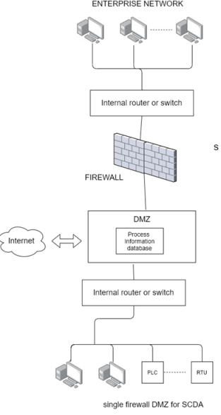
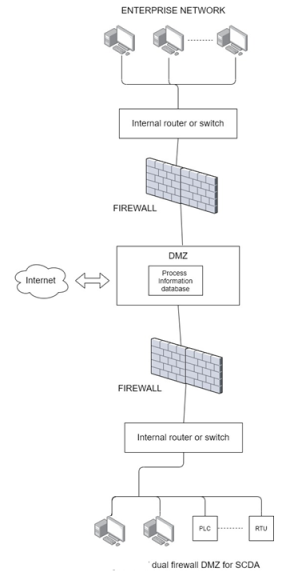
Table 6-6 Firewall Protocol Rules for Different Services to SCADA Systems
Protocol | Rule |
File Transfer protocol (FTP) | FTP permitted on outbound communications only. Should employ an encrypted VPN tunnel and token based two factor authentication. Inbound communications not permitted. |
Trivial File Transfer protocol (TFTP) | TFTP should not be permitted |
Simple Mail Transfer protocol (SMTP) | Outbound email messages permitted; inbound email messages blocked |
Telnet | Outbound communications should employ an encrypted VPN tunnel to known devices inbound communications should employ an encrypted VPN tunnel and token based two factor authentication. |
Hypertext Transfer Protocol (HTTP) | Inbound communications should not be permitted unless necessary. If required, http should be used with the secure sockets layer (SSL) Protocol (HTTP/S). SSL provides encryption and authentication capabilities. Communications from the enterprise should be configured in the firewall to block Java and other scripts. |
Simple Network Management Protocol (SNMP) | SNMP communications should not be permitted unless implemented over a different, secure network. |
SCADA and Industrial Protocol | Because security was not considered in the design of these protocols, communications should be prohibited to and from the enterprise Network and limited to the process control networks and related process control information networks. |
Q15) What is Virtual Private Network?
A15) A virtual private network or VPN is a highly effective solution for transmitting data security over the internet or a wide area network. A VPN is said to create a secure tunnel in an untrusted Network and through a Firewall, through which sensitive data can be transmitted.
The Tunnel is created by encapsulating, or by encapsulating and encrypting, the data and then transmitting it over the network. Typically, data is encapsulated by adding a header and then encrypted before being transmitted. A VPN securely connecting two networks is illustrated in figure 3-18.
