Unit 6
Diode rectifier
Q1) Explain single phase half wave rectifier with R load ?
A1) A single-phase half-wave rectifier circuit is depicted below. This rectifier has a resistive load. This rectifier is the simplest form of diode single-phase rectifiers.
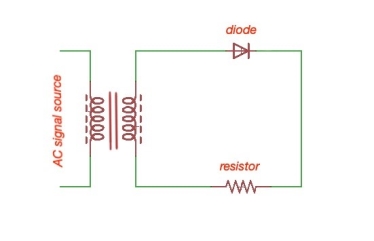
Figure 1. Single-phase half-wave rectifier circuit.
During the positive part the sinus signal diode conducts, during the negative part the sinus signal diode stops conducting. Let’s assume that the voltage transformer is , and the resistor voltage and resistance are and , diode voltage is . Then the wave forms for the diode are the following:
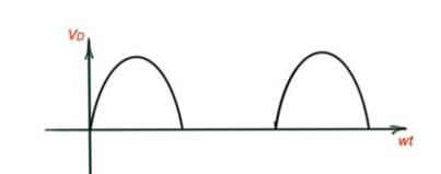
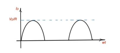
Figure 2. Voltage and current for the diode of the single-phase half-wave rectifier.
The average value of the output voltage Vdc or Vo or Vavg is determined by finding the area under the curve over a full cycle.
Vs = Vm sin(wt)
Vo = Vavg = Area / T
= 1/T  L (t)
L (t)
=1/2 π  m (t) sin(wt) d(wt) = Vm/
= Vm /2π[ -cos (wt) ] 0 π
= Vm/ 2 π [ - cos (π) – (-cos (0))]
= Vm / 2 π [ -(-1) –(-1) ] = Vm /π
= Vm/π
The dc component of the current for purely resistive load is
Io = Vo/R = Vm/π R
The root-mean-square value of the output voltage Vrms
Vrms =  1/2π
1/2π  m (t) sin(wt)] 2 d(wt) = Vm/2
The rms value of the output current Irms
Irms = Vrms / R
Average power absorbed by the resistor can be computed as
Po = Vo . Io = I 2 rms . R = V 2 rms / R
Q2) Explain single phase half wave rectifier with R-L load ?
A2)
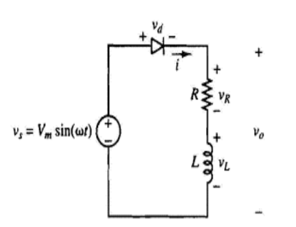
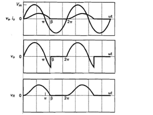
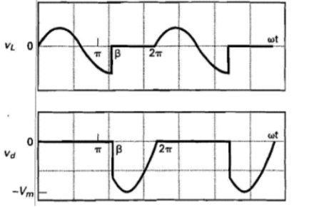
VL is negative because the current is decreasing that is
VL = L . Di/dt
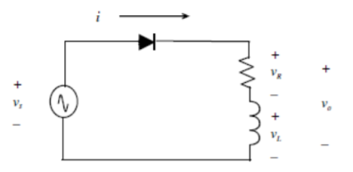
KVL vs = vR + vL
Vm sin(wt) = i(wt) R + Ldi(wt)/d wt
First order differential equation
Solution
i(wt) = if(wt) + in(wt)
Where if is the forced response
In is the natural response
The forced response is
If (wt) = (Vm/Z) . Sin(wt – Ɵ)
Where
Z =  R 2 + (wL) 2
Ɵ = tan-1 (wL/R)
Natural response is when source =0
i(wt) R + L di(wt)/ d wt =0
Which results in
in(wt) = A e – wt/wτ ; τ = L/R
Hence
i(wt) = if(wt) + in(wt) = (Vm/Z) sin (wt -Ɵ) + A e-wt/wτ
A can be solved by realising inductor current is zero before the diode starts conducting that is
i(0) = (Vm/Z) sin (0-Ɵ) + A e -0/wτ
-- A = (Vm/Z) . Sin(-Ɵ) = (Vm/Z) sin (Ɵ)
Therefore the current is given as,
i(wt) = (Vm/Z) [ sin(wt – Ɵ) + sin(Ɵ) e -wt/wτ ]
Note : The diode remains in forward biased longer than π radians . The point when current reaches zero is when diode turns OFF. This point is known as the extinction angle β.
i(β) = (Vm/Z) . [ sin ( β-Ɵ) + sin(Ɵ) . e -β/wτ] =0
Which reduces to:
Sin (β-Ɵ) + sin(Ɵ) e -β/wτ =0
β can be solved numerically. Therefore the diode conducts between 0 and β.
The average DC current is given by
Io = 1/ 2 π (wt) d wt = 1/ 2 π
  dwt
dwt
The RMS current is
I rms =  ½ π
½ π  2 (wt) d wt =
  1/ 2 π
  dwt
dwt
Power Calcuation:
Power absorbed by the law is given by
Po = (Irms) 2 R
Power factor = P/S
Where P is the real power supplied by the source which is equal to the power supplied by the load.
S is the apparent power supplied by the source
S = (Vs,RMS) . (IRMS)
Pf = P /(Vs,RMS) . (IRMS)
Q3) Explain full wave rectifier with R-load ?
A3)
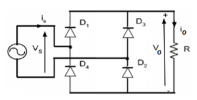
Figure shows full wave rectifier with resistive load. Sometimes it is referred as bridge rectifier. When the supply voltage (vs) is positive D1 and D2 conduct and when the supply voltage is negative D3 and D4 conduct.
Since the load is a resistive load the load current will have the same waveform as the load voltage io=vo/R.
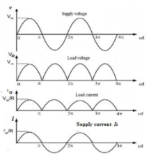
The average value of the load Vdc can be calculated as follows :
Vdc = 1/ π  sin wt dwt
= Vm / π (-cos π + cos 0) = 2 Vm / π
The value is seen to be twice the corresponding value of the half -wave rectifier.
The average value of the load current Idc
Idc = Vdc/R = 2 Vm/ π.R
Pdc = Vdc Idc = V 2 dc/R
Vo rms = 
 2 (wt) d wt
= 
 sin wt 2 (wt) d wt
= (Vm) 2 / π  (1-cos2wt) d wt
= Vm / 
The rms value of the load current Io rms is
Io rms = Vo rms / R = Vm /  2 R
2 R
The output a.c power is given by
Pac = Vo rms . Io rms = Vo 2 rms / R = (0.707Vm) 2 / R
The PRV for any diode in this configuration is Vm . The load voltage ripple factor is
RF =  Vo 2 rms – V 2dc / Vdc = 0.48
The average and rms values of the supply current are,
Is(av) = 1/2π  (1-cos2wt) d wt =0
Is(rms) =  1/2π
1/2π  / R sinwt) 2 d wt
= Vm /  R
R
Q4) Explain Centre tapped Full wave rectifier ?
A4)
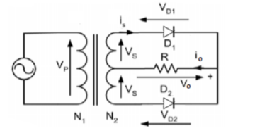
This rectifier is as shown in figure. The waveform and analysis are same as for the bridge rectifier.
Q5) For the single phase full-wave rectifier the supply voltage is 110V , 50 Hz the load resistor is 25 Ω calculate :
(a) The average value of the output voltage and current
(b) The rms value of the output voltage and current
(c) The dc power consumed by the load (Pdc) and the average value of the power delivered to the load (Pac)
A5) The average value of the output load voltage:
Vdc = 1/ π  sin wt d wt = 2Vm/π = 2
 x 110/ π = 99.035 V
The average value of the load current
Idc =Vdc/R = 99.035/25 = 3.961 A
(a) The rms vaue of the load voltage Vo rms
Vo rms = 
= Vm /  =
=  x 110/
  = 110
= 110
Io(rms) = Vo rms /R = 110/25 = 4.4A
(b) The dc power Pdc = V2 dc /R = (99.035) 2 / 25 = 392.31 W
Pac = Vo 2 rms /R = (110) 2/ 25 = 484 W
Q6) Explain full wave rectifier with R-L load ?
A6) Highly inductive loads are basically R-L loads where L >>>R . Therefore the load time constant τ = L/R is very high and can be considered infinity. The load current is assumed constant. The load current is assumed constant. For one total period of this circuit the corresponding waveforms are shown in figure .
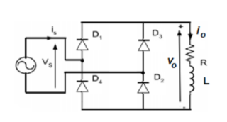
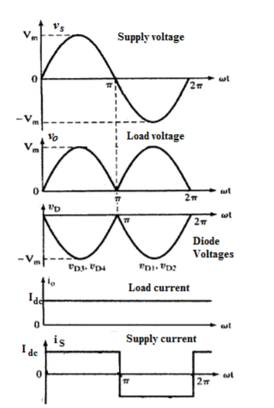
During the conduction of D1 and D2 simultaneously the supply voltage appears directly across the load so that the load voltage vo(wt) remains the form as shown in figure. Hence the average value of the load voltage Vdc can be calculated as
Vdc = 1/ π  sin wt d wt = Vm/π(-cos π + cos 0) = 2 Vm/π
Since the load is highly inductive load the load current is considered constant and its average value is
Idc = Vdc /R = 2 Vm / π R
And the d.c power is
The rms value of the load volatge Vrms can be calculated as follows :
Vo rms =  2 dwt
2 dwt

 dwt = Vm
Therefore the rms value of the load current Iorms is
Io rms = Vrms /R = Vm /  2 R
2 R
Since the load current is constant the rms value of the load current Io rms is
Io rms = Idc = Ia
The output power AC is given by
Pac = Vo rms . Io rms = Vo 2 rms /R = (0.707Vm) 2 /R
Q7) Explain three phase full wave rectifier?
A7)
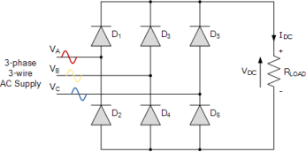
Assume a phase rotation of Red-Yellow-Blue (VA – VB – VC) and the red phase (VA) starts at 0o. Each phase connects between a pair of diodes as shown. One diode of the conducting pair powers the positive (+) side of load, while the other diode powers the negative (-) side of load.
Diodes D1 D3 D2 and D4 form a bridge rectifier network between phases A and B, similarly diodes D3 D5 D4 and D6 between phases B and C and D5 D1 D6 and D2 between phases C and A.
Thus diodes D1 D3 and D5 feed the positive rail and depending on which one has a more positive voltage at its anode terminal conducts. Likewise, diodes D2 D4 and D6 feed the negative rail and whichever diode has a more negative voltage at its cathode terminal conducts.
Then we can see that for three-phase rectification, the diodes conduct in matching pairs giving a conduction pattern for the load current of: D1-2 D1-6 D3-6 D3-6 D3-4 D5-4 D5-2 and D1-2 as shown.
Full-wave Three-phase Rectifier Conduction Waveform
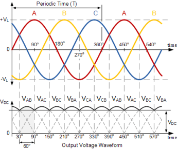
In 3-phase power rectifiers, conduction always occurs in the most positive diode and the corresponding most negative diode. Thus as the three phases rotate across the rectifier terminals, conduction is passed from diode to diode.
Then each diode conducts for 120o (one-third) in each supply cycle but as it takes two diodes to conduct in pairs, each pair of diodes will conduct for only 60o of a cycle at any one time as shown above.
Therefore we can correctly say that for a 3-phase rectifier being fed by “3” transformer secondaries, each phase will be separated by 360o/3 thus requiring 2*3 diodes. Therefore it can be fed by a star connected or a delta connected transformer supply.
So the average DC value of the output voltage waveform from a 3-phase full-wave rectifier is given as:
Vdc = 3  / π . Vs = 1.65 X Vs
Where: VS is equal to (VL(PEAK) ÷ √3) and where VL(PEAK) is the maximum line-to-line voltage (VL*1.414).
Q8) A 3-phase full-wave bridge rectifier is required to fed a 150Ω resistive load from a 3-phase 127 volt, 60Hz delta connected supply. Ignoring the voltage drops across the diodes, calculate: 1. The DC output voltage of the rectifier and 2. The load current.
A8) 1. The DC output voltage:
The RMS (Root Mean Squared) line voltage is 127 volts. Therefore the line-to-line peak voltage (VL-L(PEAK)) will be:
VL (peak) = VL (RMS ) x  = 127 x 1.414 = 179.6 V
As the supply is 3-phase, the phase to neutral voltage (VP-N) of any phase will be:
Vs = VL (peak) 
 = 179.6
  1.732 = 103.& V
Note that this is basically the same as saying:
Vs = VL (RMS) x  /
/  = 103.7V
Thus the average DC output voltage from the 3-phase full wave rectifier is
VDC = [3  /
/  ] Vs = 1.654 x Vs
VDC = 1.654 x 103.7 = 171.5V
Again, we can reduce the maths a bit by correctly saying that for a given line-to-line RMS voltage value, in our example 127 volts, the average DC output voltage is:
VDC = 3  VL (RMS) = 1.35 x 127 = 171.5V
2. The rectifiers load current.
The output from the rectifier is feeding a 150Ω resistive load. Then using Ohms law the load current will be:
I LOAD = Vs  RL = 171.5
  150 = 1.14 Amps.
Q9) What are the applications of rectifiers?
A9)
- Rectifying a voltage, such as turning the AC into DC voltages.
- Isolating signals from a supply.
- Voltage Reference.
- Controlling the size of a signal.
- Mixing signals.
- Detection signals.
- Lighting systems.
- LASER diodes.
Q10) What are the applications of three phase rectifiers ?
A10)
- Phase rectifiers are also used as the input supply of motor drives for high power motors.
- They are also used in the field excitation in power plants.