Unit - 1
Classification Of Measuring Instruments
Q1) What are the essentials for indicating instruments?
A1) Indicating instruments consist essentially of a pointer moving over a calibrated scale & attached to the moving system pivoted on bearings. Torque is required for proper functioning of these instruments which includes Deflecting, Controlling, & Damping Torque.
Q2) Explain the Dynamic System of an Indicating Instrument?
A2) They are concerned with the measurement of quantities that vary with time. It describes its behavior between the time a measured quantity changes value and the time when the instrument output attains a steady value in response. As with static characteristics, any values for dynamic characteristics quoted in instrument data sheets only apply when the instrument is used under specified environmental conditions. Outside these calibration conditions, some variation in the dynamic parameters can be expected. A dynamic system is represented by differential equation. The dynamic behavior of measurement is studied in two domains: Time Domain & Frequency Domain.
Mathematical Model
A measurement system can be represented by ordinary linear differential equation with constant coefficients. The relationship can be represented as


Where, 

a’s & b’s = constants representing the physical parameters of the system
The above representation relates  &
&  in time domain. The solution of this equation can be obtained either by method of D operates or by the Laplace Transform.
Q3) What do you understand by Calibration & explain its necessity?
A3) Calibration is a comparison of measuring equipment against a standard instrument of higher accuracy to detect, correlate, adjust, rectify and document the accuracy of the instrument being compared. Typically, calibration of an instrument is checked at several points throughout the calibration range of the instrument. The calibration range is defined as “the region between the limits within which a quantity is measured, received or transmitted, expressed by stating the lower and upper range values.” The limits are defined by the zero and span values. The zero value is the lower end of the range. Span is defined as the algebraic difference between the upper and lower range values.
Need for Calibration
Instrument error can occur due to a variety of factors: drift, environment, electrical supply, addition of components to the output loop, process changes, etc. Since a calibration is performed by comparing or applying a known signal to the instrument under test, errors are detected by performing a calibration. An error is the algebraic difference between the indication and the actual value of the measured variable. Typical errors that occur include:
Zero and span errors are corrected by performing a calibration. Most instruments are provided with a means of adjusting the zero and span of the instrument, along with instructions for performing this adjustment. The zero adjustment is used to produce a parallel shift of the input-output curve. The span adjustment is used to change the slope of the input-output curve. Linearization error may be corrected if the instrument has a linearization adjustment. If the magnitude of the nonlinear error is unacceptable and it cannot be adjusted, the instrument must be replaced. To detect and correct instrument error, periodic calibrations are performed. Even if a periodic calibration reveals the instrument is perfect and no adjustment is required, we would not have known that unless we performed the calibration. And even if adjustments are not required for several consecutive calibrations, we will still perform the calibration check at the next scheduled due date. Periodic calibrations to specified tolerances using approved procedures are an important element of any quality system.
Q4) What are the major difference between attraction & repulsion type of moving iron instruments?
A4) An attraction type will have a lower inductance than the repulsion type, and voltmeters will, therefore, be accurate over a wider range of frequency and there is a greater possibility of using shunts with ammeters. On the other hand, repulsion instruments are more suitable for economical production in manufacture and nearly a uniform scale is more easily obtained they are therefore more much common than the attraction type.
Q5) What is an Instrument Transformer?
A5) Instrument transformer is a type of an electrical transformer that is used for the measurement of voltage, currents and power in AC circuits. The level of currents and voltages are very high, therefore the direct measurement of these electrical quantities is not possible practically. In such a case, the instrument transformer is being used to step down the voltage and current within a range.
There are two types of instrument transformer available: Current Transformer & Potential Transformer.
Q6) Derive an equation of Torque for Attraction Type Moving Instrument?
A6) 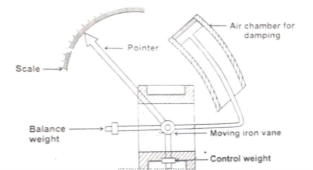
Let ‘ϴ’ be the deflection corresponding to a current of ‘i’ ampere.
Let the current increases by ‘di’, corresponding deflection is ‘ϴ+dϴ’
There is change in inductance since the position of moving iron change wrt the fixed electromagnets.
Let the new inductance value be ‘L+dL’. The current change by ‘di’ is dt seconds
Let the emf be induced in the coil be ‘e’ volt

Multiplying by  in the above equation


The above equation gives the energy & used in two forms. Part of energy is stored in the inductance. Remaining energy is converted in to mechanical energy which produces deflection.
Change in Energy stored = Final Energy – Initial Energy stored


Mechanical work done to move the pointer by 

By law of conservation of energy
Electrical Energy supplied = Increase in stored energy + mechanical work done


At steady state condition 


When the instruments measure AC,  rms
rms
Scale of the instrument is non uniform
Q7) Describe the Core & Windings used in a Current Transformer?
A7) Current Transformer’s Core & Winding
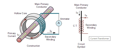
Core
The core has low reluctance & low core losses, in order to minimize the errors due to magnetizing current & core loss component. The reduction of reluctance path can be brought about by using materials of high permeability, short magnetic path, large cross section area & a low value of flux density. Magnetic materials used to design the core are Hot Rolled Silicon Steel, Cold Rolled Grain Oriented and Nickel Iron Alloys.
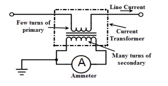
Windings
(i) Wound Transformer: In this transformer the primary winding is composed inside the transformer. The primary winding had a single turn and connected in series with the conductor that measured the current. The wound transformer is mainly used for measuring the current from 1amps to 100 amps.
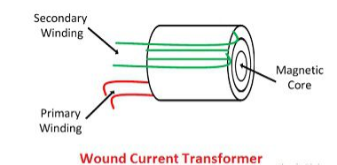
(ii) Bar Type Current Transformer: The bar type transformer has only secondary windings. The conductor on which the transformer is mounted will act as primary windings of the current transformers.
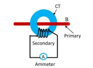
Toroidal Current Transformer: This transformer does not contain primary windings. The line through which the current flow in the network is attached through a hole or a window of the transformers. The major advantage of this transformer is that the transformer has a symmetrical shape due to which it has a low leakage flux, thus less electromagnetic interference.
Q8) Explain the Capacitor Potential Transformer?
A8) The circuit diagram of the capacitor potential transformer is shown in the figure below. The stack of high voltage capacitor from the potential divider, the capacitors of two sections becomes C1 and C2, and the Z is the burden.
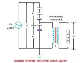
The voltage applied to the primary of the intermediate transformer is usually of the order 10kV. Both the potential divider and the intermediate transformer have the ratio and insulation requirement which are suitable for economical construction.
The intermediate transformer must be of very small ratio error, and phase angle gives the satisfactory performance of the complete unit. The secondary terminal voltage is given by the formula shown below.

Q9) An ammeter has a full-scale deflection of 100mA and a resistance of 50ohms. The ammeter is used to measure the current in a load of resistance 500ohms when the supply voltage is 10 V. Calculate (a) the ammeter reading expected (neglecting its resistance) & (b) the actual current in the circuit the power dissipated in the ammeter, and (d) the power dissipated in the load?
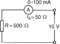
A9) (a) Expected ammeter reading = V/R D 10/500 = 20mA.
(b) Actual ammeter reading = V/(R+ra) = 10/(500+50) = 18.18 mA. Thus the ammeter itself has caused the circuit conditions to change from 20mA to 18.18 mA.
(c) Power dissipated in the ammeter = I2ra = (18.18*10-3)2(50) = 16.53mW
(d) Power dissipated in the load resistor = I2R = (18.18*10-3)2(500) = 165.3 mW
Q10) Write the equations of Transformation Ratio, Nominal Ratio, Turns Ratio & Ratio Correction Factor for Current & Potential Transformer?
A10) Transformation Ratio
 For Current Transformer
 For Potential Transformer
Nominal Ratio
 For Current Transformer
 For Potential Transformer
Turns Ratio
 For Current Transformer
 For Potential Transformer
Where,
IP = Primary Current
Is = Secondary Current
Vs = Secondary Voltage
VP = Primary Voltage
NS = Secondary Turns
NP = Primary Turns
Ratio Correction Factor (RCF)


The ratio marked on the transformer is their nominal ratio