Unit - 4
Measurement Of Energy
Q1) What is Electrical Energy?
A1) Electrical Energy is defined as the form of energy which is caused by the movement of the electrons from one point to another, then such type of energy is called electrical energy. In other words, electrical energy is nothing but the work done by the moving electrons or charges in the electric field.
Electrical energy can be either potential energy or kinetic energy. But it's usually encountered as potential energy, which is energy stored due to the relative positions of charged particles in the electric fields. The movement of charged particles through a conducting medium (conductors or wires) is called Current Electricity.
Q2) Derive the formula for Electrical Energy?
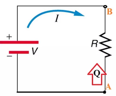
A2) To develop Electrical Energy formula, let us consider a simple circuit which contains an energy source (battery), a Resistance and a conducting wire to complete the path for current.
Let us assume the potential difference between point A and Point B is V volts. If a charge Q coulomb travels from point A to B in time t sec. Then, Current I amp is flowing through resistance R in the circuit.
Then work done by the charge will be V*Q joules.
Since Electrical Power is defined as electrical work done per unit time. So in the differential form, we can write as

Since current (I) = dQ/dT
So we can write Power (P) = V*I watts
If current I flows through conductor for a time t sec then total work done by the charge Q will be
E = V*I*t joules
Hence the formula for Electrical Energy will be
E = V*I*t joules

Q3) What is Induction Type Energy Meter with constructional diagram?
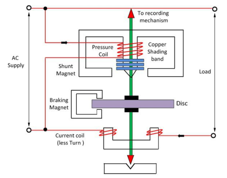
A3) The meter which is used for measuring the energy utilizes by the electric load is known as the energy meter. The energy is the total power consumed and utilized by the load at a particular interval of time. It is used in domestic and industrial AC circuit for measuring the power consumption. The meter is less expensive and accurate.

It has four parts;
(i) Driving System
(ii) Moving System
(iii) Braking System
(iv) Registration (Counter)
Q4) A consumer uses a 8 KW geezer, a 5 KW electric press and four 100 watt bulbs for 10 hours. How many units (KWh) of electrical energy have been used?
A4) Total Power Consumed= 8+5+(400/100) = 13.4 KW
time Taken = 10 hours
Therefore, Energy Drawn = 13.4*10 = 134 Kilowatt hour
Q5) What is a Three phase energy meter with its principle?
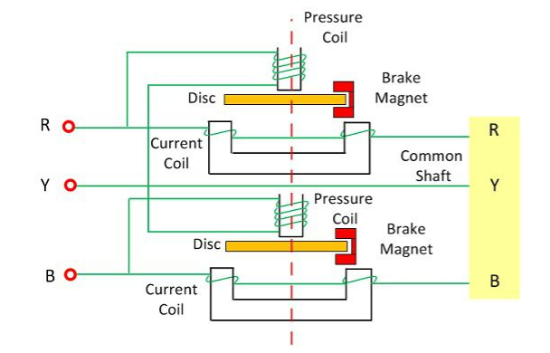
A5) The meter which is used for measuring the power of three phase supply is known as the three phase energy meter. The three phase meter is constructed by connecting the two single phase meter through the shaft. The total energy is the sum of the reading of both the elements. The torque of both the elements is added mechanically, and the total rotation of the shaft is proportional to the three phase energy consumption.
Q6) Explain the constructional detail of Three phase energy meter?
A6) The three phase energy meter has two discs mounted on the common shaft. Both the disc has its braking magnet, copper ring, shading band and the compensator for getting the correct reading. The two elements are used for measuring the three phase power. The construction of the three phase meter is shown in the figure below.
For three phase meter, the driving torque of both the elements is equal. This can be done by adjusting the torque. The torque is adjusted by connecting the current coils of both the elements in the series and their potential coils in parallel. The full load current is passed through the coil due to which the two opposite torque is set up in the coil.
The strength of both the torques are equal, and hence they do not allow the disc to rotate. If the torque becomes unequal and the disc rotates then the magnetic shunt is adjusted. The balance torque is obtained before testing the meter. The position of the compensator and the braking magnet are separately adjusted to each of the element for obtaining the balance torque.

Q7) Explain TOD (Time of Day) Meter?
A7) Time of Day metering (ToD), also known as Time of Usage (ToU), metering involves dividing the day into tariff slots with higher rates at peak load periods and low tariff rates at off-peak load periods. While this can be used to automatically control usage on the part of the customer (resulting in automatic load control), it is often simply the customer’s responsibility to control his own usage, or pay accordingly(voluntary load control). This also allows the utilities to plan their transmission infrastructure appropriately.TOD metering normally splits rates into an arrangement of multiple segments including on-peak, off-peak, mid-peak and critical peak. A typical arrangement is a peak occurring during the day, such as from 5 pm to 11 pm. By Implementing the Automated Meter Data Acquisition System coupled with GIS the utility will not only be able to find out the accurate Technical Losses occurring from Feeder to DT to HT but also find out the reason of such losses
Q8) Derive the torque equation of an energy meter?
A8) Let
V – applied voltage
I – load current
∅ – the phase angle of load current
Ip – pressure angle of load
Δ – the phase angle between supply voltage and pressure coil flux
f – frequency
Z – impedance of eddy current
∝ – the phase angle of eddy current paths
Eep – eddy current induced by flux
Iep – eddy current due to flux
Eev – eddy current due to flux
Ies – eddy current due to flux
The net driving torque of the disc is expressed as
 Where,
K1 = Constant
 = phase angle between fluxes
 = phase angle between
  = (
= ( )
)
Driving Torque,

As we know 
Therefore,

If f, Z and  are constants then,

If N is steady speed, braking torque,
At steady state, the speed of the driving torque is equal to braking torque If
If 
Speed; 
 The speed of rotation is directly proportional to the power
Total number of revolution = 
If 
Total number of revolutions = 
Q9) What are the errors in Induction type energy meter?
A9)
Phase angle error
Error due to friction at light loads
Creeping error
Error due to change in temperature
Error due to over load
Error due to voltage variations
Q10) Explain the working of Energy Meter?
A10) The energy meter has the aluminum disc whose rotation determines the power consumption of the load. The disc is placed between the air gap of the series and shunt electromagnet. The shunt magnet has the pressure coil, and the series magnet has the current coil. The pressure coil creates the magnetic field because of the supply voltage, and the current coil produces it because of the current.
The field induces by the voltage coil is lagging by 90º on the magnetic field of the current coil because of which eddy current induced in the disc. The interaction of the eddy current and the magnetic field causes torque, which exerts a force on the disc. Thus, the disc starts rotating.
The force on the disc is proportional to the current and voltage of the coil. The permanent magnet controls their rotation. The permanent magnet opposes the movement of the disc and equalizes it on the power consumption. The cyclometer counts the rotation of the disc.
The pressure coil has the number of turns which makes it more inductive. The reluctance path of their magnetic circuit is very less because of the small length air gap. The current Ip flows through the pressure coil because of the supply voltage, and it lags by 90º.
The Ip produces the two Φp which is again divided into Φp1 and Φp2. The major portion of the flux Φp1 passes through the side gap because of low reluctance. The flux Φp2 goes through the disc and induces the driving torque which rotates the aluminium disc.
The flux Φp is proportional to the applied voltage, and it is lagged by an angle of 90º. The flux is alternating and hence induces an eddy current Iep in the disc.
The load current passes through the current coil induces the flux Φs. This flux causes the eddy current Ies on the disc. The eddy current Ies interacts with the flux Φp, and the eddy current Iep interacts with Φs to produce the another torque. These torques are opposite in direction, and the net torque is the difference between these two.