Unit 1
Transformers
Q.1) Derive the emf equation of the transformer.
Sol: 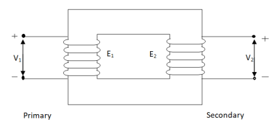
An ideal transformer has no losses i.e. its winding having no magnetic leakage and no ohmic resistance. Hence, an ideal transformer has only two purely inductive coils wound on a loss-free core.
Fig. Ideal Transformer
For above transformer when secondary is open and primary is having input sinusoidal voltage V1. An alternating -current flows due to difference in potential. As primary coil is purely inductive so, Iµ current is drawn through it. This current is very small and logs V1 by 900.
The current Iµ produces magnetic flux φ and hence are in same phase. The flux is linked with both the windings and hence, self-induced emf is produced E1 which is equal and opposite of V1. Similarly, E2 is induced in secondary which is mutually induced emf E2 is proportional to rate of change of flux and number of secondary windings.
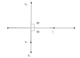
The phasor is shown below.
Fig. Phasor for Ideal Transformer
Emf Equation of Transformer:
N1 = No of primary turns
N2 = No of secondary turns
Φm = max flux in cone (wb)
Φm = Bm x A
f = Frequency of input(ac) Hz
Average rate of change of flux
= Φm / ¼
= 4 ΦmF volts
Average emf per turn = 4F ΦmV
As Φ varies sinusoidally rms value of induced emf is given as
Form factor = r.m.s value / average value = 1.11
r.m.s value of emf/turn = 1.11 x 4f Φm
= 4.44 f Φm volt
r.m.s value of induced emf in primary winding
= (induced emf/turn) x No of primary turns
E1 = 4.44 fN1 Φm
E1 = 4.44 fN1BmA
r.m.s emf induced in secondary
E2 = 4.44 fN2 Φm
E2 = 4.44 fN2BmA
E1/E2 = N1/N2 = K
K – voltage transformation
(i). If N2 > N1 i.e K > 1 STEP UP TRASFORMER
(II). If N1 > N2 i.e K<1 STEP DOWN TRASFORMER
FOR Ideal Transformer
V1 I1 = V2 I2 = 1/K
Hence, current is inversely proportional to the voltage transformation ratio.
Q.2) Describe in brief the open circuit and short circuit test of transformer?
Sol:
(1) OPEN CIRCUIT TEST:
Basically, these tests are performed to find the basic parameters of transformers. The open circuit test is performed to determine no-load loss (core loss) and no-load current I0 which is helpful in finding X0 and R0.
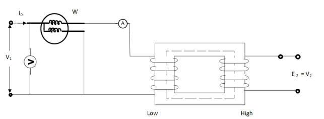
Fig. Open Circuit Test
In this test the high voltage winding is left open and the other is connected to supply.
A wattmeter W, voltmeter V and an Ammeter A are connected to L.V. Winding.
Due to applied voltage in primary, flux is set up in core, and hence normal iron loss occurs. This is recorded in Wattmeter. The current I0 is measured by Ammeter A.
Wattmeter reading represents core loss under no-load condition.
The wattmeter reading will be given as
W = V1 I0 cos φ0
Iµ = I0 Sin φ0
Iw = I0 cos φ0
X0 = V1/Iµ, R0 = V1/Iw
At no load I0 ≈ Iµ
I0 = V1 Y0
Y0 – Exciting Admittance
W = V21 G0
G0 – Exciting conductance
B0 = √ Y20 – G20
B0 – Exciting susceptance
(2) SHORT CIRCUIT TEST:
This test is used to determine
(i). Equivalent Impedance (Z01, Z02), leakage reactances (X01 or X02), Total resistance (R01, R02).
(ii). Cu losses are also calculated at full load.
(iii). The regulation of transformer can be determined as Z01, Z02 can be calculated.
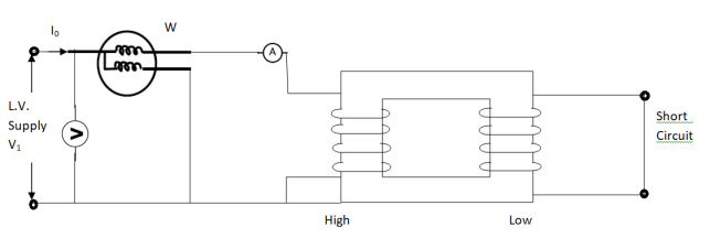
Here low voltage is short circuited. And the supply is through high voltage (primary here).
As applied voltage is small, hence the flux φ induced is also small.
As core losses are very small, the wattmeter reading is the cu-loss at full load for whole transformer.
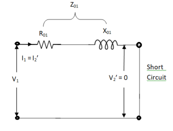
The equivalent circuit is shown below,
Z01 = Vsc/I1
Vsc = voltage to circulate rated load current
W = I21 R01
R01 = W / I21
X01 = √ Z201 – R201
R’2 = R01 – R1
Q.3) The core of a 110 KVA, 10,000/500v, 50 Hz, 1-Φ core type transformer has a cross section of 18 cm x 18 cm. Find the number of HV and LV turns per phase and the emf per turn if the maximum core density does not exceed 1.3 tesla. Assume a stacking factor pf 0.9.
Sol: Bm= 1.3T
Area = (0.18 x 0.18) = 0.032m2
Emf induced in primary
E1 = 4.44 fN1BmA
10000=4.44 x 50 x N1 x 1.3 x 0.032
N1=1082.8
Emf induced in secondary
E2 = 4.44 fN2BmA
500= 4.44 x 50 x N2 x 1.3 x 0.032
N2= 54.14
i) The number of turns is N1=1082.8 and N2= 54.14
Ii) Emf per turn = E1/E2 = N1/N2 = K
=10000/1082=9.24V or 500/54.14=9.23V
Q.4) A 1-Φ transformer has 400 turns in primary and 110 turns in the secondary. The cross-sectional area of the secondary. The cross-sectional area of the core is 80cm2. If the primary winding is connected to the 50 Hz supply at 500V. Calculate peak flux density in core.
Sol: As we know Emf induced in primary
E1 = 4.44 fN1BmA
500 = 4.44 x 50 x 400 x Bm x (80x10‑4)
Bm=0.704Wb/m2
Q.5) A 2000/200v transformer draws a no-load primary current of 0.6A and absorbs 360 watts find the magnetising and iron loss currents.
Sol: Iron loss current = = 360/2000=0.18A
I20 = I2w + I2µ
Magnetising component Iµ = √I20 – I2w
= √ (0.6)2 – (0.18)2
Iµ = 0.57 A
Q.6) A 2200/250 V transformer takes 0.7A at a p.f of 0.4 0n open circuit. Find the magnetising and working component of no load primary current?
Sol: I0= 0.7A
Cosφ0=0.4
Iw= I0 cosφ0
Iw=0.7 x 0.4=0.28A
Magnetising component Iµ = √I20 – I2w
= √ (0.7)2 – (0.280)2
Iµ = 0.64 A
Q.7) A single phase transformer has 400 turns in primary and 1000 turns in secondary. The cross-sectional area is 80 cm2. If primary is connected to 50hz at 500V. Voltage induced in secondary?
Sol: As we know Emf induced in primary
E1 = 4.44 fN1BmA
500= 4.44x50x1000xBmx(80x10-4)
Bm= 0.28Wb/m2
The voltage induced in secondary is given as
E1/E2 = N1/N2 = K
E2=1000x500/400=1250V
Q.8) A 200 KVA, 1200/200v, 50 Hz, 1-Φ transformer has a leakage impedance of (0.1 + 0.30) Ω for the HV winding and (0.005 + 0.015) Ω for the LV winding. Find the equivalent winding resistance, reactance and impedance referred to the HV and LV side.
Sol: The Turn ratio is given as E1/E2 = N1/N2 = K
K=6
i) Referring to High Voltage Side
Resistance = R1+K2R2= 0.1+ 62 x 0.005 =0.28ohm
Reactance = X1+K2X2= 0.30+ 62 x0.015 = 0.84ohm
Impedance = √0.282 +0.842
=0.880hm
Ii) Referring to Low voltage sides
Resistance= R1/ K2+R2= (0.1/62) + 0.005=0.007ohm
Reactance = Reactance HV side/ K2=0.84/62=0.013ohm
Impedance = Impedance referring HV/ K2= 0.88/62 = 0.024ohm
Q.9) When a transformer is connected to a 1200v,50Hz supply the core loss is 900 W, of which 600 is hysteresis and 350 W is eddy current loss. If the applied voltage is raised to 2000V and frequency to 100 Hz. Find new core losses.
Sol: Hysteresis Loss (Wh) α  f =P
f =P  f
f
Eddy current Loss (We) α P f2 = Q
  f
f
The emf equation of transformer is given as E= 4.44fNBmaxA
Bmax α E/f
So, the above equations become Wh = P (E/f)2 f = P E1.6 f-0.6
600= P x 12001.6 x 50-0.6
P=0.074
The eddy current loss We= Q (E/f)2 f2 = QE2
350=Q x 12002
Q=0.243 x 10⁻³
Now the applied voltage is raised to 2000V so finding new losses with above found P and Q
Wh = P E1.6 f-0.6 = 0.074 x 20001.6 x 100-0.6 = 893.06W
We= QE2 = 0.243 x 10-3 x 20002 = 972 W
Q.10) A short circuit test when performed on HV side of a 12kVA,2000/400v, 1-Φ transformer the data is:50v, 3A, 100W. If the LV side is delivering full load current at 0.8 p.f and at400v, find the Voltage applied to HV side.
Sol: As the test is done from HV side which is primary side
Z01=50/3 = 16.67ohm
R01= 100/32 = 11.11ohm
X01=  16.672 – 11.112 = 12.42ohm
I1= 12x1000/2000 = 6A
Voltage drop referred to primary is E = I1(R01 cosφ + X01 sinφ)
= 6 (11.11 x 0.8 + 12.42 x 0.6)
E = 98.04V
Q.11) A transformer has cu loss of 1.5% and the reactance drop of 3.2% when tested at full load. Calculate its full load regulation at unity power factor.
Sol: Approx. Voltage regulation at unity p.f (full load) = 0.015 cos φ + 0.032 sin φ= 0.015 = 1.5%
Approx. Voltage regulation at 0.08 lagging p.f = 0.015 x 0.8 + 0.032 x 0.6 = 0.032=3.2%
Approx. Voltage regulation at 0.08 leading p.f = 0.015 x 0.8 – 0.032 x 0.6
= 7.2x10-3= -0.72%
Q.12) A 20kVA 440/220V 1-phase transformer 50Hz has iron loss of 289W. The Cu losses found to be 60W and delivers half of full load current. Determine percentage of full load when the efficiency will be maximum?
Sol:  =
= 
Full load Cu loss = 22 x 100 = 400W
 =
=  =
= = 0.85
Hence, efficiency will be maximum at 85%
Q.13) A 20kVA, 1-Φ transformer,50Hz,500/250v gave following results
OC test (LV side): 230v,2.8A,200W
SC test (LV side): 15v,30A,300W
Calculate the efficiency at full load 0.8 p.f lagging.
Sol: Full load current = 20000/230 = 86.96A
SC current is measured till 30A on low voltage side.
I2R losses 40A n low voltage side = (40/30)2 x 300 = 533.3W
Iron loss for OC test = 200W
Full load output at p.f 0.8 = 20000 x 0.8 =16kW
Efficiency = {(16x1000)/[16000+200+533.33]} = 0.956 = 95.6%
Q.14) Explain in detail about the losses that occur in transformer?
Sol:
Core or Iron Loss:
This includes both hysteresis loss and eddy current loss. Iron or core loss is found from open circuit test.
Hysteresis Loss(Wh) = nB1.6max f V Watt
Eddy current Loss(We) = P B2max f2 t2 Watt
Copper Loss:
This is due to ohmic resistance of the transformer windings.
Total cu loss = I21 R1 + I22 R2
= I21 R01 + I22 R02
Cu loss α I2
The value of cu loss is found from short-circuit test.
Q15) Derive the condition for maximum transformer efficiency.
Sol:
Condition for maximum efficiency:
For n to be maximum dn/dI1 = 0
(Ww) cu loss = I21 R01 or I22 R02
Iron loss = Hysteresis loss + Eddy current loss
= Wn + We = Wi
n = Input – losses/Input
Primary Input = V1I1 Cosφ1
n = V1 I1 Cosφ1 – losses/V1 I1 cos φ1
n = V1 I1 cos φ1 – I21 R01 – Wi / V1I1 cosφ1
= 1 – I1R01/V1cosφ1 – Wi/V1I1cosφ1
Differentiating w.r.t I1 both sides of above equation we have
Dn/dI1 = 0 – R01/V1cosφ1 + Wi/V1I21 Cosφ1
For max value dn/dI1 = 0
R01/V1cosφ1 = Wi/V1I21 cosφ1
Wi = I21 = I21 R01
Hence,
Wi = Wcu
Iron loss = copper loss
The value of output current for maximum efficiency will be
I2 = √Wi/R02
The maximum efficiency can also be given as,
nmax = full load x √ Iron loss / F.L .cu loss
Or
nmax = R’ x full load KVA x pf / R’ x full load KVA x pf + Wi + Wcu x 100
R’ = ratio of actual to full load KVA
Wi = iron loss (KW)
Wcu = copper loss (KW)