Unit 4
D. C. Machines (Part-2)
Q1) Explain in detail the characteristics of DC shunt motor.
Sol: a) Torque and Armature current characteristics: As relation between torque and armature current is Ta α φ Ia , assuming φ to be practically constant. So, Ta α Ia and the characteristics are linear as shown below.
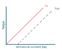
Fig: Torque versus Armature current
b) Speed and Armature current characteristics: N α Eb/φ , for φ to be practically constant N α Eb . But both Eb and φ decrease with increasing load. The drop varies from 5 to 15% of full load speed. As Eb decreases more than φ speed decreases.
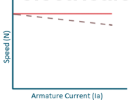
Fig: Speed verses Armature current characteristics
c)Speed and Torque Characteristics: From above to characteristics, curve for this shown below.
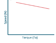
Fig: Speed verses Torque characteristics
Q2) Explain speed control of DC series motor.
Sol: a) Torque and Armature current characteristics: As we have already seen that armature torque Ta is proportional to the product of flux linked and the armature current
Ta α φ Ia
Since φ α Ia
Ta= I2a
As Ta is proportional to the square of armature current, the curve is Parabolic as shown below.
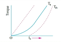
Fig: T v/s Ia characteristics
b) Speed and armature current characteristics: As we know speed (N) is related to back emf as
N α Eb/φ
But φ α Ia .
So, as the value of Ia increases the vale corresponding value of φ also increases. So, N αEb/ Ia
As the speed increases the value of current decreases (inversely proportional). For various values of load current there is very small change in the value of Eb, hence can be neglected here. The curve is shown below.
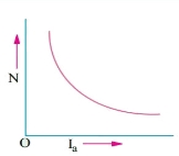
Fig: Speed verses Armature current characteristics
c) Speed and Torque characteristics: As Ta α φ Ia and φ α Ia , but N αEb/ Ia .So it can be easily concluded that speed and torque are inversely proportional. Hence when speed is high torque is low and vice versa. The curve is shown below.
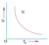
Fig: Speed verses Torque characteristics
Q3) What is commutation and also explain the types of commutation.
Sol: Basically, commutation means reversal of current in DC machines. In DC motors commutation is used to reverse the directions of DC current before being applied to the coils of the motor. The device used for commutation is called as commutator. The basic principle on which a motor works is electromagnetic induction. When current is passed through a conductor it produces magnetic field lines around it.
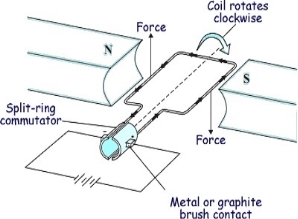
Fig: Motor effect
The conductor having magnetic field induced around it when placed in the path of magnetic lines of forces, they block the path. To remove this obstacle the lines of forces move either up or down according to the current direction. This gives rise to motor effect. Now if electromagnetic coil is placed between two magnets with opposite poles facing each other, the magnetic lines move the coil up when current is in one direction and down when current in opposite direction. This develops rotatory motion in coil. To change the direction of current in the coil, two half-moon shaped metals are attached to each end of the coil called Commutator. Metal brushes are placed with one end attached to the battery and the other end connected to the commutators.
Commutation in DC Machine
The armature coil has two commutators connected to its ends. When commutators and brushes are in contact current transformation can be attained. In DC machines we use more than one coil. As shown in below figure.
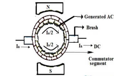
Fig: Commutation
Hence, we have more than one pair of commutator segments. The coil is short-circuited for a very short period of time with the help of brushes. This period is known as commutation period.
Reactance voltage: The coil in armature slot has self-inductance L. As we already know the direction of current is reversed in commutation. So, due to reversal of current and self-inductance a voltage is induced equal to  . This voltage is also known as Reactance voltage.
Reactance voltage=
Tc= Commutation period.
I is maximum change in current in either direction.
So total change in current = I-(-I) = 2I
Reactance voltage=
1.11 is form factor of sinusoidal waveform.
Q4) The armature winding of a 6-pole 250V dc shunt motor is lap connected. There are 100 slots, each slot containing 8 conductors. The flux per pole is 20mW and current taken by the motor is 25A. The resistance of armature and field circuit are 0.1 and 125ohm. If rotational losses are 800W find i) gross torque ii) useful torque iii) efficiency.
Sol: Ish=250/125=2A
Ia=25-2=23A
Eb=250-(23x0.1) = 247.7V
Eb=
247.7=
 )
)
N=928.87rpm
i) Gross torque Ta=9.55  =9.55x
 58.57N-m
Ii) Cu loss in armature= 232 x 0.1=53W
Shunt Cu loss=250x2=500W
Rotational Losses=800
Total motor loss=800+500+53=1353W
Motor input=250x25=6250W
Motor output=6250-1353=4877W
Tsh=9.55 x  = 9.55x
  =50.14 N-m
Iii) Efficiency =  =
=  = 0.78= 78%
Q5) A 230V shunt motor on no load runs at 1000rpm and takes 5A. Armature and shun field resistances are 0.3 and 250ohm. Calculate the speed when load taking a current of 50A. The armature reaction weakens the field by 4%.
Sol: Ish= 230/250=0.92A
Ia1=5-0.92=4.08A
Ia2=50-0.92=49.08A
Eb1=230-(4.08 x 0.3) =228.776V
Eb2=230-(49.08 x 0.3) =215.276V
 =
= =940.99rpm
Q6) A 6-pole, 440V wave connected shunt motor has 1000armature conductors and flux/pole of 20mWb. The armature and field resistances are 0.4 and 250ohm. What will be the speed and torque developed by the motor when it draws 20A from supply? If magnetic and mechanical losses are 850W. Find i) useful torque ii) output in kW
Sol: The useful torque is given by Tsh=9.55 x 
Ta=
Ish=440/250=1.76A
Ia=20-1.76=18.24A
Eb=440- (18.24 x 0.4) = 432.70V
But we already know Eb=
432.70 =
N= 432.70 rpm
Ta= =
= =174.19 N-m
Ii) For output we need Motor input and total losses
Armature Cu loss = 18.242 x 0.4=133.08W
Field Cu loss = 440 x 1.76=774.4W
Iron and Friction loss= 850W
TOTAL LOSS= 133.08 + 774.4 + 850= 1757.48W
Motor input= 440 x 20=8800 W
Output = 8800-1757.48=7042.52W
i) Tsh=9.55 x  =9.55 x
  = 155.43 N-m
Q7) A 250V dc shunt motor has an armature resistance of 0.4ohm and field resistance of 250ohm. When driving a load of constant torque at 700rpm, the armature current is 20A. If it is desired to raise the speed from 550 to 650rpm, what resistance should be inserted in the shunt field circuit.
Sol: As we already know
 =
=  (1)
(1)
The torque relation is given as
Ta α  Ia
Ia
For load with constant torque we can say
 Ia2 α
Ia2 α  Ia1
Ia1
Ia2 = Ia1 x  = Ia1 x
Ish1= 250/250 = 1A
Ish2= 250/Rt
Rt= Total resistance of shunt field circuit
Ia2= 20 x 
But we also that Eb1= 250- (20 x 0.4) =242V
Eb2 = 250- ( =250-
=250-
From the equation 1 above
 =
=  x
x 
55 – 343.75 x
  + 98.3 x
  = 0
= 0
Solving above equation we get
 =300.4Ω
The value of addition shunt resistance required will be 300.5 – 250=50.5Ω
Q8) A 250V shunt motor has an armature resistance of 0.5 ohm and takes an armature current of 35A on a certain load. What amount the main flux will reduce to raise the speed by 50% if torque is constant.
Sol: As we already know
 =
= 
 Ia2 α
Ia2 α  Ia1
Ia1
Ia2 = Ia1 x 
Eb1= 250- (35 x 0.5) = 232.5V
Eb2= 250- (35k x 0.5)
Let 
As we need to raise the speed by 50% then  =
= 
Substituting in above equation we get
 =
=  x k
x k
35k2-500k + 697.5=0
K = 1.56
The other value of k does not hold for this question.
 =1.56
=1.56
So, the percentage reduction in the main flux will be given as

 = 35.89%
Q9) What are the causes of bad commutation. Suggest the remedies.
Sol: By saying bad commutation, we only mean Sparking and burning while commutation. It can occur because of following reasons:
1.When Brushes position is not proper.
2. When spaces between brushes is not proper. This may be checked by marking an adding-machine tape around the commutator.
3. Mica should be between bars undercut about 0.063 in below the commutating surface.
4.When commutator is not ground, resulting in rough or burned commutator. Rough or burned commutator.
5. Grooved commutator. This may be prevented by properly staggering the brush sets so that the spaces between the brushes of an arm are covered by brushes of the same polarity of other arms.
6.When it has poor brush contact. It may be due to improper fitting of brush to commutator surface.
7.The brushes are not replaced correctly, i.e of same size or grade.
8.When the brushes do not move freely in their holder, irregularity occurs. This is called sticking brushes.
9.When operated for current density below 35A/in2,may lead to chattering of brushes. This can be corrected by lifting brushes to raise density
10. Due to poor line up or inadequate foundation Vibration occur.
11.The Short-circuited turns on the commutating or compensating fields can be the reason for bad commutation.
12. Because of open or very high resistance joints between the commutator neck and the coil leads can lead to the burning of bar at the bad joint.
13. A broken coil conductor produces an effect similar to that produced by the poor joints. In case of emergency the open coil may be opened at both ends, insulated from the circuit, and a jumper placed across the two affected necks.
14.With the resulting unbalanced air-gap fluxes under the poles, large circulating currents must be expected even with good armature cross connections.
15. Overloading.
Remedies:
There are basically three methods of improving commutation.
i)Resistance Commutation
Ii)Voltage Commutation
Iii)Compensation Windings
Below are explained briefly the methods of improving commutation
i) Resistance Commutation: The Resistance Commutation can be obtained by replacing low resistance copper brushes with high resistance carbon brushes. The use of Carbon brushes makes the contact resistance between commutator segments and brushes high. This high contact resistance has the tendency to force the current in the short-circuited coil to change according to the commutation requirements.
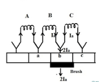
Fig: Resistance commutation
As seen from figure above Ia from the coil C cab reach brushes from two paths in commutation period. One path is direct through the commutator segment b and to the brush and the 2nd path is first through the short-circuit coil B and then through the commutator segment a and to the brush. The second path is shorter. When we use high resistance brushes then the contact area of brush with B decreases and contact area with A increases. But the resistance is inversely proportional to the contact area. So, Ra will decrease and Rb will increase according to the movement of brush.
Ii)Voltage Commutation: This method has two ways to improve commutation
a) Brush Shift
b) Commutating poles or interpoles.
In this method a voltage is induced in the coil undergoing commutation. This will help to neutralise the reactance voltage. The both voltages are opposing each other. So, when injected and reactance voltages are equal, the direction of current in short circuited coil reverses, helping to attain sparkles commutation.
a) Brush Shift: The effect of armature reaction is to shift the magnetic neutral axis (MNA) in the direction of rotation for the generator and against the direction of rotation for the motor. Armature reaction establishes a flux in the neutral zone. A small voltage is induced in the commutating coil since it is cutting the flux.
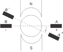
Fig: Brush Shift
b) Interpoles: The main function of interpoles is to induce an emf which is equal and opposite to that of reactance emf, which makes commutation sparkles. They also neutralize the cross-magnetizing effect of armature reaction.
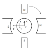
Fig: Interpoles
In above figure OF=MMF due to main poles.
OA=Cross Magnetizing MMF due to armature
BC= MMF due to interpoles.
BC is in opposition to OA. Hence it helps to cancel cross magnetization due to OA.
The ampere turns needed to cancel armature reaction ampere turn and to create the required flux is given as
ATi=ATa(peak)+
Bi=Flux density in interpole air gap
 =air gap of interpoles
Q10) A 220V dc shunt motor has an armature resistance of 0.25ohm and runs at 900rpm. With armature current of 40A. The speed to 700rpm is required. If armature resistance remains same, find the additional resistance to be connected in series with the armature.
Sol: Eb= 220 - (40 x 0.25) =210V
As the armature current does not change then Eb  Speed
Speed
220  900
900
So, for speed to be 700
Eb1  700
700
Eb1 = [700/800] x 220=192.5V
The additional resistance required will be
220 – (R+0.25) x 40=192.5
R= 0.44Ω
Q11) A 230V shunt motor with armature resistance of 0.4 ohm runs at 550rpm on full load and takes an armature current of 20A. 1ohm is placed in the armature circuit. Find speed at full load torque.
Sol: We already know that  =
= 
But as flux is constant  =
= 
 = 230-(0.4 x 20) = 222V
T α φ Ia
As flux is constant T α Ia

But  =
=  and
and  =20A
=20A
Eb2= 230 - [20 x (0.5+1)] = 200V
Now the speed at full load torque is
 =
= 
N2 = x 550 = 478.26rpm
Q12) A series motor is running on a 400V circuit with a regulating resistance of R ohm. The total resistance of armature and field coil is 0.3 ohm. On certain load with R=0, the current is 18A and speed is 1000rpm. With another load and R=4 ohm the current is 12A. Find new speed and let the field at 18A be 60% of that at 12A?
Sol: Eb1= 400 – (18 x 0.3) = 394.6V
Eb2= 400- [12 x (0.3+4)] = 348.4V
As the field at 18A is 60% of that at 12A. Hence, we can write
 = 0.6
= 0.6 
 =
= 
N2 = 1000 x  = 1472 rpm
Q13) A 440V, 4 pole, 20kW, dc generator has a wave connected armature winding with 800 conductors. The mean flux density in the air gap under interpoles is 0.5Wb/m2 on full load and the radial air gap length is 0.3 cm. Calculate the number of turns required in each pole?
Sol: From equation ATi=ATa(peak)+ =
=
Ia=20,000/440=45.45A
ATi= =3466.16
Ni= =
= =76.26=76
Hence 76 turns are required in each pole.
Q14) Explain Ward Leonard method of speed control.
Sol: Ward-Leonard System: The figure below shows the ward-Leonard system. In this method speed of motor M1is controlled which is powered by generator G. The shunt field of motor is connected across DC supply. The motor M2derives the generator. When the output voltage of the generator is fed to the motor M1 then the motor starts to rotate. When the output voltage of the generator varies then the speed of the motor also varies. By controlling the output voltage of generator speed of motor can be controlled. To attain this a field regulator is connected across the generator. The direction of rotation of motor can be reversed by excitation current of generator, this will happen by reversing the switch R.S. The motor-generator should run in same direction.
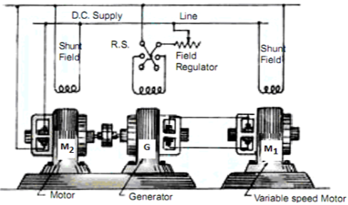
Fig: Ward Leonard System
Q15) A 250V shunt motor on no load runs at 900rpm and takes 4amperes, armature and shunt field resistances are 0.2 and 250 ohms respectively. Calculate the speed when loaded taking current of 50A. The armature reactions weaken the field by 3%?
Sol: Ish=250/250=1A
Ia1=4-1=3A
Ia2=50-1=49A
Eb1=250-3*0.4=248.8V
Eb2=250-49*0.2=240.2A


N2=898rpm
Q16) List the applications of DC motors.
Sol: Series Motor: They are used in Electric locomotives, Cranes, Hoists, Conveyors and cars.
Shunt Motor: They are used for Blowers, Fans, centrifugal pumps, for driving constant speed line shafting lathes.