Unit 5
Three Phase Induction Motor
Q1) Illustrate with proper figure the principle of working of three phase induction motor.
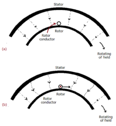
Sol: The fundamental principle of induction machine is the creation of rotating and sinusoidally distributed magnetic field in the air gap. Three phase balanced power supply is fed to the three-phase stator winding creates a synchronously rotating magnetic field. Due to relative speed between rotating flux and stationary conductors, an emf is induced. The frequency to induced emf is same as supply frequency.
As shown in below fig.a, the stator field is assumed to clockwise. The relative motion of rotor w.r.t stator is anticlockwise. From Right-hand rule, the direction of induced emf in rotor is outwards. By the effect of combined field as shown in fig b the rotor experiences a force tending to rotate it in clockwise direction. Hence rotor rotates in the same direction as the stator field.

The speed of this rotating field is called synchronous speed. If the rotor is initially stationary, its conductors will be subjected to a changing magnetic field, inducing current in the short-circuited rotor at the same frequency. The interaction of air gap flux and rotor mmf produces torque. At synchronous speed rotor cannot have ant torque.
Q2) Explain torque-slip characteristics with the operating regions.
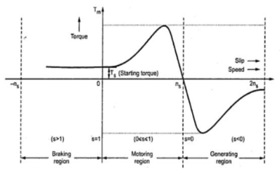
Sol: The below curve can be divided into three regions.

Fig: Torque-Slip Characteristics
i) Motoring Region(0≤s≤1): The induction motor rotates in the same direction as that of the field. Here the speed decreases and torque increases till breakdown torque is reached. In this region air-gap flux is nearly constant. After breakdown torque Tmax, torque decreases and slip increases.
Ii) Generating Region(s<0): In this machine operates as a generator. The rotor rotates at a speed greater than synchronous speed in same direction as that of rotating magnetic field. Due to super synchronous speed the slip becomes negative and creates negative regenerative torque.
Iii) Plugging Region(1≤s≤2): Here slip becomes greater than unity. So, motor rotates in the opposite direction of the rotating magnetic field. Here the stator field is reversed by changing the phase sequence of input supply, due to this the direction of rotating magnetic field also changes. Here torque is positive but speed is negative. So, plugging torque appears as breaking torque. This method of breaking is called plugging.
Q3) Explain with phasor the production of MMF by 3-phase supply.
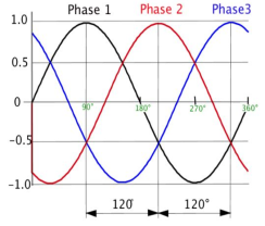
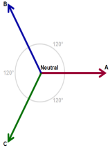
Sol: The 3-phase windings are displaced by 120º in space, are fed by three phase currents, and displaced by 120º in time as well. They produce magnetic flux.


Fig: Three phase winding
Let φm be the maximum value of lux. The resultant flux is the vector sum of individual fluxes φ1, φ2, φ3 due to three phases.
i) When  i.e point 0, in above graph
φ1=0 φ2= φm and φ3=
 φm
φm
φr= 2 x  φm x cos30
 φm
φm
Ii) When  (i.e blue line curve)
φ1= φm φ2=
 φm and φ3=0
The resultant flux φr= 2 x  φm x cos30
 φm
φm
The resultant flux gain is rotated clockwise through 
Iii) When  (red line curve)
φ1= φm φ2=
 and φ3=
 φm
φm
The resultant flux is φr= 2 x  φm x cos30
 φm
φm
The resultant again has same value but further rotated clockwise 
Iv) When 
φ1=0 φ2= φm and φ3=
 φm
φm
The resultant again is φr= 2 x  φm x cos30
 φm but has rotated clockwise through
Q4) Mention the losses in a three phase IM.
Sol: In general, we can categorise losses as:
i) Constant losses: They remain constant over the normal working range of induction motor. By no-load test we can find these losses. The losses falling in this category are Iron or core loss, Mechanical Loss and Brush Friction loss.
a) Iron or core loss: The core losses depend on the frequency of supply voltage. As the frequency of rotor is always less than that of stator. Hence, core loss in rotor is less compared to that of stator. The core loss can be further classified as hysteresis and eddy current losses.
b) Mechanical and Brush Friction Loss: These are low at starting and increases with increase in speed. In induction motor speed is usually constant hence these losses also remain constant. Mechanical losses occur in bearings and brush friction losses occur in wound rotor induction motor.
Ii) Variable losses: These losses occur due to current flowing in stator and rotor windings. As the load changes, the current flowing in rotor and stator winding also changes and hence these losses also change. Therefore, these losses are called variable losses. The copper losses are obtained by performing blocked rotor test on three phase induction motor.
Q5) A 1200V 50Hz delta connected IM has a star connected slip ring rotor with phase transformation ratio of 3.6. The rotor resistance and standstill leakage reactance are 0.012 and 0.25 ohm per phase. Find the rotor current with slip ring shorted. The power factor at start with slip ring shorted.
Sol: In this case the primary phase voltage is same as line voltage.
The rotor phase standstill voltage = 1200 x [1/3.6] = 333.3V
a) Rotor impedance/phase =  = 0.2503Ω
b) Rotor phase current at start = 333.3/0.2503=1331.8A
Power Factor = 0.012/0.2503=0.048 lagging
Q6) A rotor of 6-pole 50Hz IM is rotated by some means at 1000 rpm. Find i) Rotor voltage. Ii) rotor frequency iii) rotor slip.
Sol: N=1000rpm
F=50Hz
The synchronous speed Ns=120f/P=120x50/6=1000rpm
i) Rotor voltage Er=sE
S=Ns-N/Ns x100 = {[1000-1000]/1000} x 100 = 0
Since, s=0 Er=0
Ii) Rotor Frequency fr=sfs
Since, s=0
fr=0
Iii) Rotor slip s=0
Q7) A star connected rotor of an IM has a standstill impedance of 0.2+j3 ohm per phase and the rheostat impedance per phase of 6+j2 ohm. The motor has induced emf of 80V. Find the rotor current at standstill with the rheostat in the circuit.
Sol: For standstill condition
Voltage/Rotor phase= 80/ = 46.2V
Starter impedance/phase = 6.2+j5=7.96
Rotor current/phase= 46.2/7.96=5.8
p.f= cos 38.88=0.778
Q8) A 3-phase 50Hz 6-pole IM has full load slip of 2%. The rotor resistance and standstill rotor reactance per phase is 0.002 and 0.048 ohm. Find the ratio of maximum full load torque and the speed at which the maximum torque occurs.
Sol: Ns=120f/P=120 x 50/6=1000rpm
Slip at max. Torque (smT) = rotor resistance/standstill rotor reactance = 0.002/0.048 = 0.042
Now the speed becomes = (1-0.042) x 1000=958rpm

 = 15.5 x 10⁻³
Q9) A 6-pole 50 Hz 3-phase IM develops a maximum torque of 158.7 N-m at 1335 rpm. The resistance of the star connected rotor is 0.2 ohm/phase. Calculate the value of resistance that must be inserted I series with each rotor phase to produce a starting torque equal to half the maximum torque.
Sol: Ns=120f/P=120 x 50/6= 1000rpm
N=1335rpm
Slip corresponding to maximum torque = (1335-1000)/1335= 0.25
Maximum Torque Tmax = 
X2=R2/slip corresponding maximum torque = 0.2/0.25=0.8ohm
Let H= 
Tmax =  = H/(2x0.8)=0.625H
Let r be the external resistance introduced per phase in the rotor circuit
Tsh =  =
= =
= 
But it’s given that Tsh =  Tmax
Tmax
 =
= 
0.625r2-1.75r+0.025=0
r=0.02Ω
Above r is the required resistance aa per the given conditions.
Q10) A 400V 3-phase 50 Hz 6-pole Y-connected IM has a full load speed of 900 rpm. The rotor has an impedance of 0.4+j4 ohm and rotor/stator turn ratio of 0.8. Calculate full load torque, rotor current and full load rotor cu loss.
Sol: Ns=120f/P=120 x 50/6=1000rpm=16.67rps
S=0.1
E1=400/ = 230.9V/phase
Full load torque is given as
Tf= =
=  =122.15N-m
Rotor Current Ir= =
=  =32.65A
Total CU Loss = 3 R = 3 x (32.65)2x 0.4 = 1279.2W
Q11) A 400V 3-phase 50 Hz 4-pole Y-connected IM has a full load speed of 800 rpm. The rotor has an impedance of 0.4+j4 ohm and rotor/stator turn ratio of 0.8. Find Maximum torque and speed at which it occurs.
Sol: Ns=120f/P=120x50/4=1500=25rps
E1=400/ = 230.9V
Maximum Torque Tmax=  =
=  =81.46.1N-m
s=R1/X1=0.4/4=0.1
Slip speed = sNs = 0.1x1500 = 150rpm
Speed for maximum torque = 1500-150 = 1350rpm
Q12) A 3-phase 400/200V, Y-Y connected wound rotor induction motor has 0.05 ohm resistance and 0.2 ohm stand still reactance per phase. Find the additional resistance required in the rotor circuit to make starting torque equal to the maximum torque of motor?
Sol: 
Given Tst=Tmax
1= , a=1
, a=1
a=
1=
r=0.15 Ω
Q13) A 17.89 kW, 6-pole, 50 Hz 3-phse IM runs at 869 rpm on full load with a rotor current /phase of 29 A. Allowing 1kW for mechanical losses. Find the resistance/phase of three phase rotor winding.
Sol: Motor output = 17.89kW
Mechanical losses = 1000W
Mechanical power developed Pm= 17.89+1=18.89kW
Ns=120f/P=120x50/6=1000rpm
S=(1000-869)/1000=0.13
Rotor Cu loss =  =
=  = 2.823kW
3 = 2823
R1=1.12Ω/phase