Unit 6
Three Phase Induction Motor
Q1) Draw and explain about the exact and approximate equivalent circuit for 3-phase IM
Sol: The case is quite similar to that of transformer. Here also the secondary values can be transferred to the primary and vice versa. The equivalent circuits are shown below
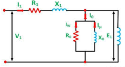
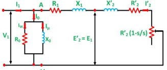
Fig.: Equivalent circuit of induction motor referred to primary
 ,
,  ,
,  =KI2,
=KI2,  =
= (1-s/s)
Whenever we shift impedance or resistance from secondary to primary, we divide it by K2. The approximate equivalent circuit is shown below.
R01=R1+
X02=X1+
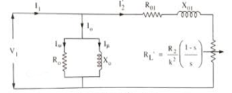
Fig.: Approximate circuit of induction motor
Q2) What are No-load and blocked rotor tests. Derive the equivalent circuit parameters.
Sol: No-load test: The no load test is carried out with different values of applied voltage, below and above the value of normal voltage range. The input power is measured by two wattmeters. I0 by ammeter and V by voltmeter. As motor is running on light load, p.f is low. The total power input will be the difference of reading of W1 and W2.
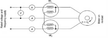
Fig.: No load test
The total power input W0 = VLI0cosφ0
Cosφ0=
Where VL= Line voltage.
W0= no load stator input.
Stator winding loss = 3Io2R1
I0 = No load input current
R1 = Resistance of the motor
Core loss = 3GoV2
Blocked Rotor Test:
A blocked rotor test is normally performed on an induction motor to find out the leakage impedance. In the blocked rotor test, the applied voltage on the stator terminals should be low otherwise normal voltage could damage the winding of the stator. In block rotor test, the low voltage is applied so that the rotor does not rotate and its speed becomes zero and full load current passes through the stator winding.
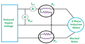
Fig.: Blocked rotor test
The slip is unity related to zero speed of rotor hence the load resistance becomes zero. Now, when the voltage is increased slowly in the stator winding so that current reaches to its rated value. At this point, take readings of the voltmeter, wattmeter and ammeter to know the values of voltage, power and current. The test can be repeated at different stator voltages for the accurate value.
Resistance and Leakage Reactance Values
The copper loss is given Wcu.
Therefore,

Where, Wc = core loss
Wcu=3I2R01
Where, R01 = Motor winding of stator and rotor as per phase referred to stator.
R01=
Thus,
Let
Is = short circuit current
Vs = short circuit voltage
Z0 = short circuit impedance as referred to stator
Z01= =
=
Therefore,
X01 = Motor leakage reactance per phase referred to stator will be
X01=
Stator reactance X1 and rotor reactance per phase referred to stator X2 are normally equal.
Hence,
X1=X2=
Similarly, stator resistance per phase R1 and rotor resistance per phase referred to stator R2 can be calculated as follows:
First some suitable tests are done on stator windings to find the value of R1 and then to find R2 subtract the R1 from R01
R2=R01-R1
Short Circuit Current for Normal Supply Voltage
To calculate short circuit current Isc at normal voltage V of the stator, we must note short-circuit current Is and low voltage Vs applied to the stator winding.

Q3) What is a star delta starter. What are its advantages.
Sol: The set up for star delta starter is shown below
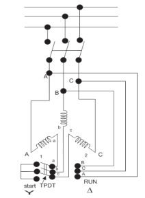
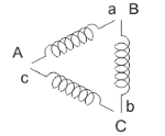
Fig.: Star delta starter
The starter phases are connected to star by TPDT (triple pole double throw switch). Initially the TPDT switch is at position 1 and when motor attains steady state switch is thrown to position 2. In position 1 terminals are short circuited and at position 2 a, b and c are connected to B, C and A. The expression for starting torque is given as
Ts starting torque
Tf Full load torque
If per phase rotor current at full load
Is per phase rotor current at starting
sf full load slip
ss starting slip
R2 rotor resistance
Ws synchronous speed of motor
In induction motor torque is given as
T=
The ratio of starting torque to full load torque is given as
 x sf
x sf
Let V1 line voltage
Iss per phase starting current
Iss=
Starting current in stator when connected in delta position
Isd=
Isd= Iss
Iss
Then the torque ratio equation will be
 x sf
x sf
This shows that the reduced voltage method has an advantage of reducing the starting current but the disadvantage is that all these methods of reduced voltage causes the objectionable reduction in the starting torque.
Q4) Why do we need to use starter in IM. Explain DOL starter.
Sol: A starter is needed for a three-phase induction motor because at the time of starting, if induction motor is started directly, it will draw a huge amount of current which can cause damage to adjoining equipment. A starter is required in an induction motor for following reasons:
- In a 3-phase induction motor, the magnitude of an induced emf in the rotor circuit depends on the slip of the induction motor. Thus, induced emf effectively decides the magnitude of the rotor current. The rotor current in the running condition is given by :
I2r = s E’2 / (R22 + sX22)
- At starting time, the speed of the motor is zero and slip is at its maximum i.e. unity. So, magnitude of rotor induced emf is very large at start. As rotor conductors are short-circuited, the large induced emf circulates very high current through rotor at start.
- The condition is exact similar to a transformer with short-circuited secondary. Such a transformer when excited by a rated voltage, circulates a very high current through short-circuited secondary. As secondary current is large the Primary current also draws very large current from the supply line.
- Similarly, in a 3-phase induction motor, when rotor current is high, the stator draws a very high current from the supply line. Due to this increase in line current the Voltage starts rising resulting in collapse of the system.
Direct on line starter (Full voltage starting method)
In this induction motor is directly connected to the 3-phase supply. The DOL starter applies full line voltage to the motor terminals.
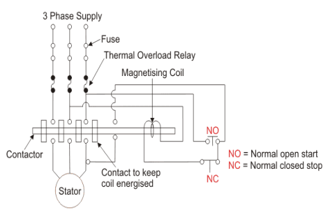
Fig.: D.O.L Starter
If the high input current does not cause any excess voltage drop in circuit than only this starter can be used. The value of armature current in motor is given as
Ia=
The expression for starting torque is given as
Ts starting torque
Tf Full load torque
If per phase rotor current at full load
Is per phase rotor current at starting
sf full load slip
ss starting slip
R2 rotor resistance
Ws synchronous speed of motor
In induction motor torque is given as
T=
The ratio of starting torque to full load torque is given as
 x sf
x sf
The wiring diagram for a DOL starter is shown above. The working principle of a DOL starter begins with the connection to the 3-phase main with the motor. The control circuit is connected to any two phases and energized from them only. When we press the start button, the current flows through magnetizing coil and control circuit also.
The current energises the contactor coil and leads to close the contacts, and hence 3-phase supply becomes available to the motor. When we stop it, the current discontinues. As the supply to motor breaks the machine stops. . The contactor coil (Magnetizing Coil) gets supply even though we release start button because when we release start button, it will get supply from the primary contacts as illustrated in the diagram of the Direct Online Starter.
The advantages of a DOL starter include:
- Simple and most economical starter.
- More comfortable to design, operate and control.
- Provides nearly full starting torque at starting.
- Easy to understand and troubleshoot.
DOL starter connects the supply to the delta winding of the motor.
Q5) Explain soft starting of IM.
Sol: A soft starter is a device that is included in the motor circuit in order to reduce the load and torque in the power train. A soft starter slowly increases the voltage in motor. This helps in smooth acceleration of power, instead of sudden rise in power, which can even damage the machine. This is achieved by limiting the value of torque in the motor. This in turn allows the soft starter to reduce the voltage and allows it to gradually stop reducing the voltage to allow for a smooth progression of current. Some soft starters use solid state devices.
Advantages of soft starter: They reduce the risk of overheating, improve the operating efficiency. There is low risk of power surge. They also reduce energy use.
Q6) What are the steps for plotting circle diagram.
Sol: For drawing circle diagram, we need to find the per phase values of no load current I0, short circuit current ISC and the corresponding phase angles Ф0 and ФSC. We also find short circuit current ISN corresponding to normal supply voltage. These all values are found through No load test and blocked rotor test on the induction motor with this data, the circle diagram can be drawn as follows
1.First of all we consider a suitable scale and then we draw vector OA with length corresponding to I0 at an angle Ф0 from the vertical axis. Then we draw a horizontal line AB.
2.Then we draw OS equal to ISN at an angle ФSC and join AS.
3. Then we draw perpendicular bisector to AS to meet the horizontal line AB at C.
4.With C as centre, we draw a portion of circle passing through A and S. This forms the circle diagram which is the locus of the input current.
5. From point S, draw a vertical line SL to meet the line AB.
6.Then divide SL at point K so that SK: KL = rotor resistance: stator resistance.
7. For a given operating point P, draw a vertical line PEFGD as shown. Then PE = output power, EF = rotor copper loss, FG = stator copper loss, GD = constant loss (iron loss + mechanical loss)
8.To find the operating points corresponding to maximum power and maximum torque, we need to draw tangents to the circle diagram parallel to the output line and torque line respectively. The points at which these tangents touch the circle are respectively the maximum power point and maximum torque point.
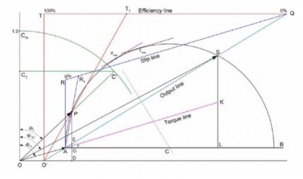
Fig.: Construction of circle diagram
The efficiency line can be drawn through following steps
1.The output line AS is extended backwards to meet the X-axis at O′.
2.From any convenient point on the extended output line, we draw a horizontal line QT so as to meet the vertical from O′. Then the line QT into 100 equal parts.
3.To find the efficiency corresponding to any operating point P, draw a line from O′ to the efficiency line through P to meet the efficiency line at T1. Now QT1 is the efficiency.
The Slip Line can be constructed by following steps:
1.Draw line QR parallel to the torque line, meeting the vertical through A at R. Divide RQ into 100 equal parts.
2.To find the slip corresponding to any operating point P, we need draw a line from A to the slip line through P to meet the slip line at R1. Now RR1 is the slip
The Power Factor Curve is drawn as follows:
1.Draw a quadrant of a circle with O as centre and any convenient radius. Divide OCm into 100 equal parts.
2.To find power factor corresponding to P, we just need to extend the line OP to meet the power factor curve at C′. Draw a horizontal line C′C1 to meet the vertical axis at C1. Now OC1 represents power factor.
Q7) A 230V 3-phase 4-pole 50 Hz Y-connected IM is rated 2.98 kW. The equivalent circuit parameters are R1=0.55ohm X1=0.6 ohm  =0.4 ohm
  =0.8 ohm. B0=-1/30 mho. The stator core loss is 50W and rotational loss is 150W. For a slip of 3%. Find i) input current. Ii)p.f
Sol: For the exact equivalent circuit Z01 = Z1+ ZAB
ZAB =  =
=  = 11.9
 =10.63+j5.57
Z01 = Z1+ ZAB= (0.55+j0.6)+( 10.63+j5.57) = 11.18+j6.17=12.76 
Vph = 230/ = 132.79
i) I1 = V1/Z01= 132.79/12.76  = 10.41
 A
A
Ii) Power factor = cos 28.89 =0.87
Q8) A 230V 3-phase 4-pole 50 Hz Y-connected IM is rated 3.98 kW. The equivalent circuit parameters are R1=0.55ohm X1=0.6 ohm  =0.4 ohm
  =0.8 ohm. B0=-1/30 mho. The stator core loss is 50W and rotational loss is 150W. For a slip of 3%. Find mechanical power, electromagnetic torque, output power.
Sol: Mechanical power is Pm= (1-s)P1
Where P1 is air gap power and given s=4%=0.04
P1= 3 2
2
ZAB =  =
=  =8.85+j3.56 = 9.29
Z01 = Z1+ ZAB = (0.45+j0.8)+(8.85+j3.56) = 9.03+j4.36 = 10
Vph = 220/ = 127
= 127
I1 = V1/Z01= 127/10 = 12.71
 A
A
P1= 3 2
2 =3 x 12.72x 8.85=4152W
i) Pm= (1-s) P1 = (1-0.04) x 4152=3986W
Ii) Electromagnetic torque Tg = 
Ns=120f/P=120x50/4=1500rpm
N=Ns(1-s) = 1500(1-0.04) =1440rpm
Tg =  =
=  = 26.4N-m
Iii) Output Power = mechanical power – rotational loss = 3986-150=3836W
Q9) What are autotransformer starter.
Sol: The Auto transformer is used in both the type of the connections, i.e., either star connected or delta connected. The auto transformer is used to limit the starting current of the induction motor. The auto transformer used is a step down, so it reduces the voltage V1 to xV1. This leads to reduction in current from I1 to xI1. After the motor reaches to its normal operating speed, the auto transformer is disconnected and then full line voltage is applied. The starting torque in terms of full load will be
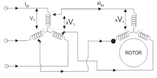
Fig.: Starting of Auto transformer
In induction motor torque is given as
T=
The ratio of starting torque to full load torque is given as
 x sf
x sf
Let rotor resistance be constant for this case. As step down transformer is used, the voltage and current decreases as mentioned above. So, the ratio of torque equation changes as
 x sf
x sf
 x sf x
  2
2
This shows the variation of the starting torque with the value of k.
Q10) A 110V 50 Hz delta connected, 6-pole IM has an equivalent T-circuit consisting of stator impedance of 0.05+j0.3 ohm and an equivalent rotor impedance at standstill of 0.09+j0.3 ohm. Magnetising branch has G0=0.029 mho, B0=0.158 mho and s=3%. Find secondary and primary currents.
Sol: We already know the equivalent circuit
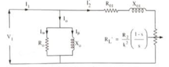
 =
=
=0.09[(1-0.03)/0.03] = 2.91Ω/phase
The impedances to the left of circuit will be
Zi = R01+ +j
+j = (0.05+0.09)+2.91+j0.6=3.05+j0.6=3.12
 Ω/phase
V=110/ = 63.51V
i) Secondary current  =I2 = V/Zi=63.51/3.12
 =19.97-j3.93A=20.35
 A
A
Ii) Primary current I1=I0+
I0=V(G0-jB0) = 63.51(0.029 – j0.158) = 1.84-j10.03A=10.20 A
A
I1=I0+ = 1.84-j10.03 + 19.97-j3.93= 21.78-j13.96A = 25.87
 A
A
Q11) A 110V 50 Hz delta connected, 6-pole IM has an equivalent T-circuit consisting of stator impedance of 0.05+j0.3 ohm and an equivalent rotor impedance at standstill of 0.09+j0.3 ohm. Magnetising branch has G0=0.029 mho, B0=0.158 mho and s=3%. Find primary p.f, gross power output, and gross torque.
Sol: Refer above question for basic values.
i) Primary p.f = cos( = 0.84
Ii) Gross power output Pg = 3 = 3 x 20.352 x 2.91 = 3615.28W
Iv) Gross torque Tg = 
Ns=120f/P=120x50/6=1000rpm
N=Ns(1-s) = 1000(1-0.03) =700rpm
Tg =  =
=  = 49.32WN-m
Q12) A 4kW,440V, 3-phase, 50Hz cage motor has a full load slip of 4.5%. The motor develops 230% of the rated torque and draws 630% of the rated current when thrown directly on the line. Find line current, motor current and starting torque if the motor was started by means of star delta.
Sol: i) Line current = (1/3) x 630= 210%
As start connected so line current = phase current
Motor current = 630/3=210%
Starting Torque = 230/3=76.67%
Q13) A 3.8kW,400V, 3-phase, 50Hz cage motor has a full load slip of 5.5%. The motor develops 210% of the rated torque and draws 620% of the rated current when thrown directly on the line. Find line current, motor current and starting torque if motor were started by connecting across 60% taps of a starting compensator.
Sol: The Line current = K2 x Isc = (60/100)2 x 620 =232.2%
Motor current = K x Isc = (60/100) x 620 =372%
Starting Torque = K2 x Tsc = (60/100)2 x 210 = 75.6%
Q14) A squirrel cage IM when started by a means of star delta starter takes 165% of full load line current and develops 35% of full load torque at starting. Calculate the starting torque and current in terms of full load values, if an autotransformer with 75% tapping were employed.
Sol: For star delta starter  =
=  sf
sf
Isc = 3 x 165 of If=4.95 If
Given  = 0.35
 = 4.95
 =
=  sf
sf
0.35=  x 4.952x sf
Sf= 0.043
K=0.75 for auto-transformer
Line starting current = K2Isc = (0.75)2 x 4.95 If= 2.78If =278% of full load current
 =K2
=K2  sf = (0.75)2 x (4.95)2 x 0.043 =0.593
Tst =0.593Tf =59.3% 0f full load torque