Unit - 3
8051 Programming in C
Q1) What are declarations?
A1) The format for declaring a variable in a C program is as follows:
Variable name;
For example, the line int i; would declare an integer variable i.
Computers are very useful when repeating a specific task, and almost every program utilizes this capability. The repetitive structures for, while, and do..while are all offered by C.
Q2) What are the data types in C?
A2) C language supports 2 different type of data types:
Primary data types:
These are fundamental data types in C namely integer(int), floating point(float), character(char) and void.
Derived data types:
Derived data types are nothing but primary datatypes but a little twisted or grouped together like array, stucture, union and pointer.
Data type determines the type of data a variable will hold. If a variable x is declared as int. it means x can hold only integer values. Every variable which is used in the program must be declared as what data-type it is.
Integers:
Integers are used to store whole numbers.
Size and range of Integer type on 16-bit machine:
Type | Size(bytes) | Range |
int or signed int | 2 | -32,768 to 32767 |
unsigned int | 2 | 0 to 65535 |
short int or signed short int | 1 | -128 to 127 |
unsigned short int | 1 | 0 to 255 |
long int or signed long int | 4 | -2,147,483,648 to 2,147,483,647 |
unsigned long int | 4 | 0 to 4,294,967,295 |
Char type
Character types are used to store characters value.
Size and range of Integer type on 16-bit machine
Type | Size(bytes) | Range |
char or signed char | 1 | -128 to 127 |
Unsigned char | 1 | 0 t0 255 |
void type
void type means no value. This is usually used to specify the type of functions which returns nothing.
Q3) What are the ports of 8051?
A3)
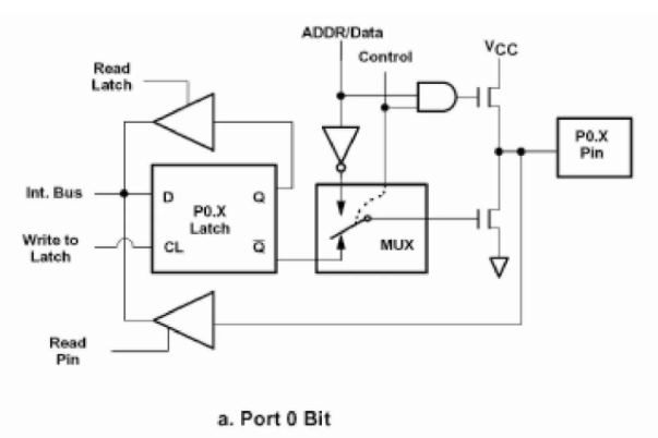
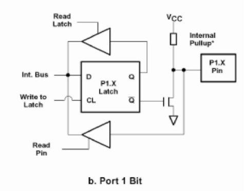
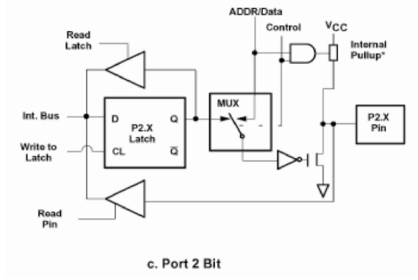
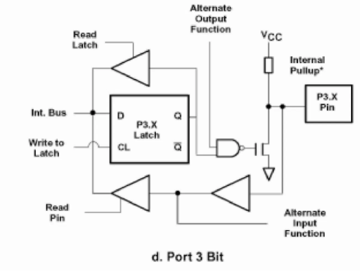
Q4) Explain the feature port0 and port 1?
A4) Features of Port 0
Functions of Port 0
When we use Port 0 as an input port, the internal latch is used for input, and thus, a digital 1 (FFH) is written at the port address of 80H. This turns off the transistors causing the pin to float in high impedance state connecting it to the input buffer. We can read data from ‘Read Pin Data’/’Read Latch Bit.’
When we use Port 0 as an output port, the latch programmed to 0 will turn on. Consequently, the FET will connect to GND. We will require an external pull up resistor(10k Ohm) here to give a logic ‘1’ for using Port 0 as an output port.
When the 8051 wants to access external memory, the address for the memory generates due to Port 0 and Port 2. We get the lower half of the address from Port 0 and the upper half from Port 2. This is done using ALE pulses, which help to latch the address to the external bus. Once done, the Port 0 goes back to being an input port to read data from that memory.
Working of port 0
Port 0 is used to read data to addresses. To configure port 0 as an input port the internal bus writes 1 to the D flip flop and the control pin is set to 0(Upper FET is OFF). The mux is connected to Q'(0) of the D flip flop as the control pin is 0. Due to this, the pin is connected to the input buffer which can be read to get the input data.
To use the port as an output port 0 is written to the D flip flop with the control signal being set to 0. This enables the lower FET and disables the upper FET due to this the pin gets connected to the ground and a zero is written to the output device.
To write a 1 to the external device the microcontroller writes 1 to the D flip flop which drives the pin to a high impedance state as it is not connected to either VCC or ground. To solve this problem a pull-up resistor is connected to the output pin which pulls the value to 5v or logic 1.
For reading Addresses or data from external memory the Control bit is set to set to 1 which connects the Mux to Data/address pin. The ALE pin is used to latch the address and once that is done the port is used for data transfer.
Features of Port 1:
The function of Port 1 – I/O port:
When Port 1 is functioning in the capacity of an input port, a digital ‘1’ (FFH) is written to the latch. At 90H. This turns off the transistor, and the pin floats in a high impedance state. Consequently, it connects to the input buffer.
When Port 1 is functioning in the capacity of an output port, the latch is given a ‘LOW’ signal (00H). This turns the FER (Field Effect Transistor) o. The pull-up resistor is OFF, and the port is used as an output port.
Q5) Explain Features of Port 2 and Port3?
A5)
Functions of Port 2
I/O port:
Quite similar to Port 0. The only difference here is that in Port 2, we use one FET with an internal pull-up resistor instead of the two FETs we saw in Port 0.
Memory Access:
Port 2 is used in conjunction with Port 0 to generate the upper address of the external memory location that needs to be accessed. However, one key difference is that it doesn’t need to turn around and get a 1 in the latch immediately for input as in Port 0. It can remain stable.
Features of Port 3
Functions of Port 3
I/O port
Just like Port 2, Port 3 can function as an input-output port.
Alternate SFR function
The input to SFR 1, we get the output of latch as 1, which turns on the NAND gate, and depending on the value of ‘Alternate Output Pin,’ FET will be wither ON/OFF.
P3 Bit | Function | Pin |
P3.0 | RxD | 10 |
P3.1 | TxD | 11 |
P3.2 |  | 12 |
P3.3 |  | 13 |
P3.4 | T0 | 14 |
P3.5 | T1 | 15 |
P3.6 |  | 16 |
P3.7 |  | 17 |
RXD: this is used for a serial input port
TXD: this is used for serial output port
INT0: this used for an external interrupt 0
INT1: this used for external interrupt 1
T0: Timer 0 external input
T1: Timer 1 external input
WR: external data memory write strobe
RD: external data memory Read strobe
Q6) Explain time delay programming in C?
A6) There are two ways to create a time delay in 8051 C:
In creating a time delay using a for loop, there are three factors:
Q7) Write a program to toggle the bits of P1 ports continuously with 250ms delay.
A7)
# include<reg51.h>
void MSdelay(unsigned int);
void main(void)
{
while(1) // repeat forever
{
P1 = 0x55;
MSDelay(250);
P1=0XAA;
MSdelay(250);
}
}
void MSdelay(unsigned int itime)
{
unsigned int i,j;
for(i=0;i<time;i++)
for(j=0;j<1275;j++);
}
Q8) Write a 8051 C program to toggle all the bits of P0 and P2 continuously with 250ms delay.
A8)
#include<reg51.h>
void MSDelay(unsigned int);
void main(void)
{
while(1)
{
P0 = 0x55;
P2 = 0x55;
MSDelay(250);
P0=0xAA;
P2=0xAA;
MSDelay(250);
}
}
void MSdelay(unsigned int itime)
{
unsigned int i,j;
for(i=0;i<itime;i++)
for (j=0;j<1275;j++);
}
Q9) Explain timers of 8051?
A9) The 8051 has two timers: timer0 and timer1. They can be used either as timers or as counters. Both timers are 16 bits wide. Since the 8051 has an 8-bit architecture, each 16-bit is accessed as two separate registers of low byte and a high byte.
Timer0 registers are 16 bits register and accessed as low byte and a high byte. The low byte is referred to as a TL0 and the high byte is referred to as TH0. These registers can be accessed like any other registers.

Figure 5. Timer 0
Timer1 registers is also a 16 bits register and are split into two bytes, referred to as TL1 and TH1.

Figure 6. Timer 1
TMOD (timer mode) Register:
This is an 8-bit register that is used by both timers 0 and 1 to set the various timer modes. In this TMOD register, the lower 4 bits are set aside for timer0 and the upper 4 bits are set aside for timer1. In each case, the lower 2 bits are used to set the timer mode and the upper 2 bits to specify the operation.

TMOD Register
M0 | M1 | Mode | Operating Mode |
0 | 0 | 0 | 13-bit timer mode. 8-bit timer/counter THx and TLx as –bit Prescaler |
0 | 1 | 1 | 16-bit timer mode, 16-bit timers/counters THx and TLx as 5-bit Prescaler |
1 | 0 | 2 | 8-bit auto-reload mode, 8-bit auto-reload timer/counter; THx holds a value which is to be reloaded into TLx each time it overflows |
1 | 1 | 3 | Split timer mode |
Mode 1-
Mode 0-
Mode 2-
Mode 3-
Mode 3 is also known as a split timer mode. Timer 0 and 1 may be programmed to be in modes 0, 1, and 2 independently of similar modes for other timers. This is not true for mode 3; timers do not operate independently if mode 3 is chosen for timer 0. Placing timer 1 in mode 3 causes it to stop counting; the control bit TR1 and the timer 1 flag TF1 are then used by timer0.
TCON Register
Bits and symbol and functions of every bit of TCON are as follows:
TF1 | TR1 | TF0 | TR0 | IE1 | IT1 | IE0 | IT0 |
TCON Register
Bit | Symbol | Functions |
7 | TF1 | Timer1 overflow flag. Set when timer rolls from all 1’s to 0 |
6 | TR1 | Timer 1 run control bit. Set to 1 by the programmer to enable a timer to count. |
5 | TF0 | Timer 0 overflow flag |
4 | TR0 | Timer 0 run control bit |
3 | IE1 | External Interrupt 1 edge flag |
2 | IT1 | External Interrupt 1 signal type control bit |
1 | IE0 | External Interrupt 0 edge flag |
0 | IT0 | External Interrupt 0 signal type control bit |
Q10) Explain timer mode and its programming?
A10) Timer Mode
In the timer mode, the internal machine cycles are counted. So this register is incremented in each machine cycle. So when the clock frequency is 12MHz, then the timer register is incremented in each millisecond. In this mode it ignores the external timer input pin.
TMOD Register
TMOD(Timer Mode) is an SFR. The address of this register is 89H. This is not bit-addressable.
The circuit that controls the running of the timers is shown in the figure.
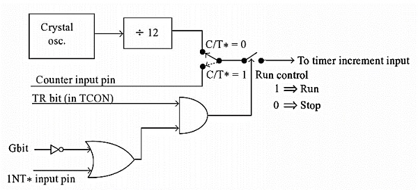
Bit Details | High Value(1) | Low Value(0) |
C/T | Configure for the Counter operations | Configure for the Timer operations |
Gate (G) | Timer0 or Timer1 will be in RunMode when TRX bit of TCON register is high. | Timer0 or Timer1 will be in RunMode when TRX bit of TCON register is high and INT0 or INT1 is high. |
Bit Details | 00 | 01 | 10 | 11 |
M1 M0 | This is for Mode 0. (8-bit timer/counter, with 5-bit pre-scaler) | This is Mode 1. (16-bit timer/counter) | This is Mode 3 (8-bit auto reload-timer/counter) | This is Mode 3 (The function depends on Timer0 or Timer1) |
In order to program 8051 timers, it is important to know the calculation of initial count value to be stored in the timer register.
The calculations are as follows. In any mode,
Timer Clock period = 1/Timer Clock Frequency. = 1/(Master Clock Frequency/12)
Upon starting the timer this value from THx will be reloaded to TLx register. (256D = FFH+1)
Steps for programming timers in 8051
Mode 1:
Load the TMOD value register indicating which timer (0 or 1) is to be used and which timer mode is selected. Load registers TL and TH with initial count values.
Start the timer with the instruction “SETB TR0” for timer 0 and “SETB TR1” for timer 1.
Keep monitoring the timer flag (TF) with the “JNB TFx, target” instruction to see if it is raised. Get out of the loop when TF becomes high.
Stop the timer with the instructions “CLR TR0” or “CLR TR1”, for timer 0 and timer 1, respectively.
Clear the TF flag for the next round with the instruction “CLR TF0” or “CLR TF1”, for timer 0 and timer 1, respectively.
Go back to step 2 to load TH and TL again.
Mode 0:
The programming techniques mentioned here are also applicable to counter/timer mode 0. The only difference is in the number of bits of the initialization value.
Mode 2:
Load the TMOD value register indicating which timer (0 or 1) is to be used; select timer mode
Load TH register with the initial count value. As it is an 8-bit timer, the valid range is from 00 to FFH.
Start the timer. Keep monitoring the timer flag (TFx) with the “JNB TFx, target” instruction to see if it is raised.
Get out of the loop when TFx goes high. Clear the TFx flag.
Go back to step 4, since mode 2 is auto-reload.
Q11) Explain counter mode and its programming?
A11) A timer can be used as a counter if we provide pulses from outside the chip instead of using the frequency of the crystal oscillator as the clock source. By feeding pulses to the TO (P3.4) and Tl (P3.5) pins, we turn Timer 0 and Timer 1 into counter 0 and counter 1, respectively.
Assume that a 1-Hz external clock is being fed into pin T0(P3.4). Write a C program for counter 0 in mode-1 (16-bit) to count the pulses and display the TH0 and TL0 registers on P2 and P1 respectively
#include(reg51.h>
void main(void)
{
T0=1;
TMOD=0x05;
TL0=0;
TH0=0;
while(1)
{
do
{
TR0=1;
P1=TL0;
P2=TH0;
}
while(TF0==0)
TR0=0;
TF=0;
}
}