Unit - 6
Measurement of electrical parameters
Q1) Explain the interfacing of current in 8051?
A1)
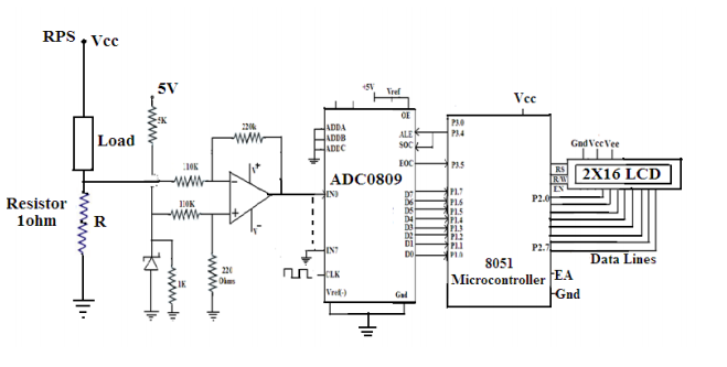
Measurement of current using 8051
Q2) Explain the measurement of voltage using 8051?
A2) Here, the input voltage should be DC voltage to get the accurate output on LCD. If AC voltage as applied as input, then you will see the continuous running numbers on LCD as AC varies continuously.
The major components are 8051 microcontrollers, a voltage sensor module and ADC0804. ADC is used to display the voltage.
The analog to digital converter IC data bits are connected to PORT2. LCD data pins are connected to the PORT3 of controller and control pins RS and EN are connected to the P1.6 and P1.7 respectively.
ADC0804
The pin9 (Vref/2) is left open so that input voltage span can be 0 to 5V.
Step size = Vref/(2 pow(n))
where n is resolution. For ADC0804 the resolution n=8. The digital output can be calculated using the formulae
Dout = Vin/stepsize.
Vin – analog input voltage
For example, let the analog input voltage is 4V, then the digital output is Dout=4/19.53mV=204.
Steps to Convert the Analog Input to Digital
1. Read the ADC value from the PORT2.
#define dat P2
val=dat*0.02;
2. After multiplying by 100, you get a positive integer value of three digits.
val1=val*100;
3. Separate individual numbers and print them on LCD including the decimal point.
temp=(((val1/100)%10)+48);
display(temp);
display(‘.’);
temp=(((val1/10)%10)+48);
display(temp);
temp=((val1%10)+48);
display(temp);
Voltage Sensor
The voltage sensor module is a simple voltage divider network that increases the analog input range of the ADC to about 25V.
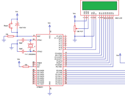

Measurement of Voltage using 8051
Q3) Explain its applications?
A3)
Q4) Explain the interfacing of Stepper motor using 8051?
A4) Stepper motor control
Stepper motors are mainly used to translate electrical pulses into mechanical movements.
They are used in some disk drives, dot matrix printers. The main advantage of using the stepper motor is the position control.
Stepper motors generally have a permanent magnet shaft (rotor), and it is surrounded by a stator.
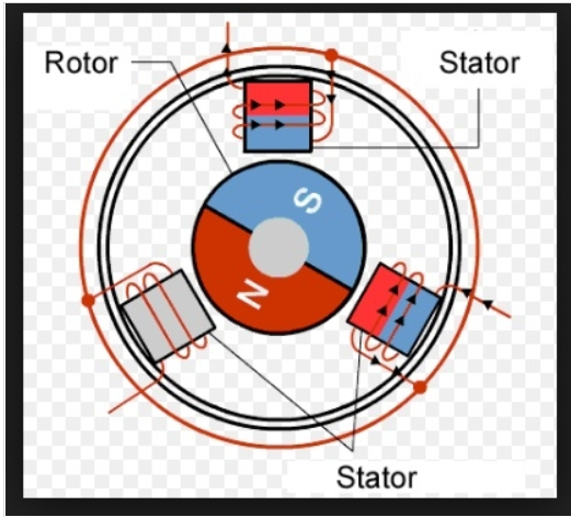
Figure 3. Stepper Motor
Parameters of stepper motors:
The relation between RPM steps per revolution and steps per second is
Steps per second = rpm x steps per revolution / 60
Interfacing
Port P0 of 8051 is used for connecting the stepper motor. HereULN2003 is used. This is a high voltage, high current Darlington transistor array. Each ULN2003 has seven NPN Darlington pairs. It can provide high voltage output with common-cathode clamp diodes for switching inductive loads.
The Unipolar stepper motor works in three modes.
Steps | Winding A | Winding B | Winding C | Winding D |
1 | 1 | 0 | 0 | 0 |
2 | 0 | 1 | 0 | 0 |
3 | 0 | 0 | 1 | 0 |
4 | 0 | 0 | 0 | 1 |
Full Drive Mode: In this mode, two coils are energized at the same time. This mode produces more torque. Here the power consumption is also high.
Steps | Winding A | Winding B | Winding C | Winding D |
1 | 1 | 1 | 0 | 0 |
2 | 0 | 1 | 1 | 0 |
3 | 0 | 0 | 1 | 1 |
4 | 1 | 0 | 0 | 1 |
Half Drive Mode: In this mode, one and two coils are energized alternately. At first, one coil is energized then two coils are energized. This is a combination of wave and full drive mode. It increases the angular rotation of the motor.
Steps | Winding A | Winding B | Winding C | Winding D |
1 | 1 | 0 | 0 | 0 |
2 | 1 | 1 | 0 | 0 |
3 | 0 | 1 | 0 | 0 |
4 | 0 | 1 | 1 | 0 |
5 | 0 | 0 | 1 | 0 |
6 | 0 | 0 | 1 | 1 |
7 | 0 | 0 | 0 | 1 |
8 | 1 | 0 | 0 | 1 |
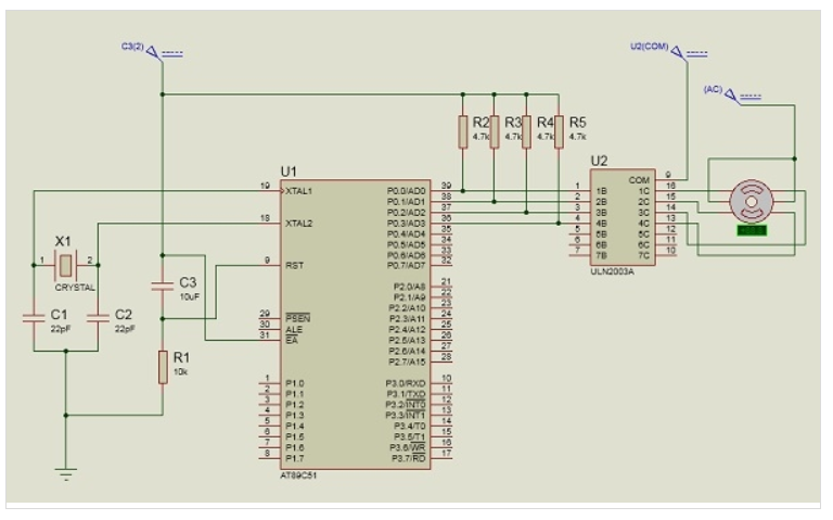
Figure 4. Interfacing Stepper Motor with 8051
Program:
#include<reg51.h>
sbit LED_pin = P2^0; //set the LED pin as P2.0
void delay(int ms){
unsigned int i, j;
for(i = 0; i<ms; i++){ // Outer for loop for given milliseconds value
for(j = 0; j< 1275; j++){ //execute in each milliseconds
;
}
}
}
void main(){
int rot_angle[] = {0x0C,0x06,0x03,0x09};
int i;
while(1){ //infinite loop for LED blinking
for(i = 0; i<4; i++){
P0 = rot_angle[i];
delay(100);
}
}
}
Q5) Explain the interfacing of single key with 8051?
A5) Matrix keyboard is used for interfacing. It is designed with a rows and columns. These rows and columns are connected to the microcontroller through its ports of 8051. Generally we use 8*8 matrix key board. So only two ports of 8051 can be easily connected to the rows and columns of the keyboard.
Whenever a key is pressed, a row and a column get shorted through that pressed key and all the other keys are left open. The bit in the port goes high which indicates the microcontroller that the key is pressed. By this high on the bit key in the corresponding column is identified.
Once we are sure that one of key in the keyboard is pressed next our aim is to identify that key. To do this we firstly check particular row and then check the corresponding column on the keyboard.
In order to check the row of the pressed key, one of the rows is made high by making one of bit in the output port of 8051 high. This is done until the row is found out. Once we get the row the next task is to detect the column of the pressed key. The column is detected by contents in the input ports with the help of a counter. The content of the input port is rotated with carry until the carry bit is set.
The contents of the counter is compared and displayed in the display. This display is seven segment display and a BCD to seven segment decoder IC 7447.
The BCD equivalent to the number of counter is sent through output part of 8051 displays the number of pressed key.

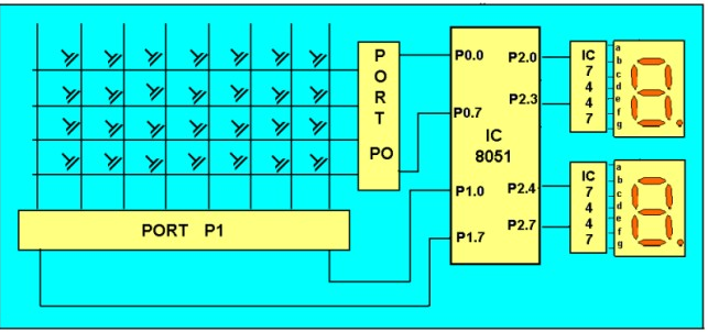
Figure. Keyboard interfacing with 8051
Steps:
2.Make all rows of port P0 high so that it gives high signal when key is pressed.
3.See if any key is pressed by scanning port P1 and by checking all columns for non- zero condition.
4.If any key is pressed, then identify which key is pressed make one row high at a time.
5.Initiate a counter to hold the count so that each key is counted.
6.Check port P1 for nonzero condition. If any nonzero number is there in [accumulator], start column scanning by following step 9.
7.Otherwise make next row high in port P1.
8.Add a count of 08h to the counter to move to the next row by repeating steps from step 6.
9.If any key pressed is found, the [accumulator] content is rotated right through the carry until carry bit sets, while doing this increment the count in the counter till carry is found.
10. Move the content in the counter to display in data field or to memory location
11.To repeat the procedures, go to step 2.
Program:
Start of main program:
to check that whether any key is pressed
start: mov a,#00h
mov p1,a ;making all rows of port p1 zero
mov a,#0fh
mov p1,a ;making all rows of port p1 high
press: mov a,p2
jz press ;check until any key is pressed
after making sure that any key is pressed
mov a,#01h ;make one row high at a time
mov r4,a
mov r3,#00h ;initiating counter
next: mov a,r4
mov p1,a ;making one row high at a time
mov a,p2 ;taking input from port A
jnz colscan ;after getting the row jump to check
column
mov a,r4
rl a ;rotate left to check next row
mov r4,a
mov a,r3
add a,#08h ;increment counter by 08 count
mov r3,a
sjmp next ;jump to check next row
after identifying the row to check the column following steps are followed
colscan: mov r5,#00h
in: rrc a ;rotate right with carry until get the carry
jc out ;jump on getting carry
inc r3 ;increment one count
jmp in
out: mov a,r3
da a ;decimal adjust the contents of counter
before display
mov p2,a
jmp start ;repeat for check next key.
Q6) Explain the interfacing of LED?
A6) Light Emitting Diodes are the semi- conductor light sources. Commonly used LEDs will have a cut-off voltage of 1.7V and current of 10mA. When an LED is applied with its required voltage and current it glows with full intensity.
The Light Emitting Diode works similar to normal PN- diode but it emits energy in the form of light. The color of light depends on the band gap of the semiconductor.
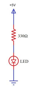
Figure. LED
LED is connected to AT89C51 microcontroller with the help of a current limiting resistor. The value of this resistor is calculated using the following formula.
R= (V-1.7)/10mA, where V is the input voltage.
The maximum output voltage of microcontrollers is 5V. Thus, the value of resistor calculated for this is 330 Ohms. The resistor can be connected to either the cathode or the anode of the LED.
Algorithm
Program:
#include<reg51.h>
#define led P0
unsigned char i=0;
void delay (int);
void delay (int d)
{
unsigned char i=0;
for(;d>0;d--)
{
for(i=250;i>0;i--);
for(i=248;i>0;i--);
}
}
void main()
{
while(1)//// led blink
{
led=0xff;
delay(1000);
led=0x00;
delay(1000);
++i;
if(i==7)
{
i=0;
break;
}
}
while(1)//// binary equivalent representation of 1byte data
{
led=i++;
if(i==256)
{
i=0;
break;
}
delay(500);
}
while(1);
}
Q7) Explain its applications?
A7)
Q8) Explain the interfacing of relay?
A8) Relays
Relays are mainly used for two basic operations.
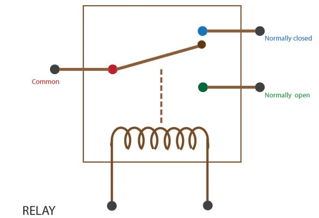
Figure. Relay
For interfacing relay with 8051, relay is connected to PORT 3 and change the relay position to ON and OFF condition.
The s-bit type defines a bit within a special function register (SFR). Here, initialize the port. The relay_pin indicates the name of SFR bit. Port 3 is the base address and ‘0’ indicates the bit position to access.

The delay function should provide the delay in a millisecond. This function is used to provide a delay while the relay works.
void Delay(int k)
{
int j;
int i;
for(i=0;i<k;i++)
{
for(j=0;j<100;j++);
}
}
Initially, the relay is in the ON condition and provide a 1-sec delay. After that, the relay is OFF and again provide a 1-sec delay. Repeat this block of code, until a condition is met.
while(1) //infinite loop
{
relay_pin = 0; //Relay ON
Delay(1000); //1 sec delay
relay_pin = 1; //Relay OFF
Delay(1000); //1 sec delay
}
Interfacing
Here the transistor is wired as a switch for interfacing relay with 8051. This transistor drives the relay. The transistor will be in OFF state when the pin P3.0 is in the LOW state. When 1 is written to P3.0 current will flow to the base of the transistor and the relay energizes.
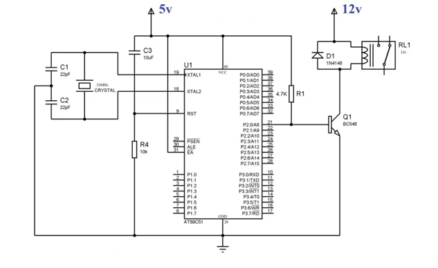
Interfacing 8051 with relay
Q9) Explain its application?
A9)
Q10) What are the advantages of relay?
A10)