Unit - 6
Network Functions
Q1) A coil takes a current of 6A when connected to a 24V dc supply. To obtain the same current with 50HZ ac, the voltage required was 30V. Calculate inductance and p.f of the coil?
A1) The coil will offer only resistance to dc voltage and impedance to ac voltage
R =24/6 = 4ohm
Z= 30/6 = 5ohm
XL = 
= 3ohm
cosφ =  = 4/5 = 0.8 lagging
Q2) The potential difference measured across a coil is 4.5V when it carries a DC of 8A. The same coil when carries AC of 8A at 25Hz, the potential difference is 24V. Find current and power when supplied by 50V,50Hz supply?
A2) R=V/I= 4.5/8 = 0.56ohm
At 25Hz, Z= V/I=24/8 =3ohms
XL = 
= 2.93ohm
XL = 2 fL = 2
 x 25x L = 2.93
L=0.0187ohm
At 50Hz
XL = 2x3 =6ohm
Z =  = 5.97ohm
I= 50/5.97 = 8.37A
Power = I2R = 39.28W
Q3) A coil having inductance of 50mH and resistance 10ohmis connected in series with a 25 F capacitor across a 200V ac supply. Calculate resonant frequency and the current flowing at resonance?
A3) f0= = 142.3Hz
I0 = V/R = 200/10 = 20A
Q4) A 15mH inductor is in series with a parallel combination of an 80ohm resistor and 20 F capacitor. If the angular frequency of the applied voltage is 1000rad/s find admittance?
A4) XL = 2 fL = 1000x15x10-3 = 15ohm
XL = 1/ C = 50ohm
Impedance of parallel combination Z = 80||-j50 = 22.5-j36
Total impedance = j15+22.5-j36 = 22.5-j21
Admittance Y= 1/Z = 0.023-j0.022 siemens
Q5) A circuit connected to a 100V, 50 Hz supply takes 0.8A at a p.f of 0.3 lagging. Calculate the resistance and inductance of the circuit when connected in series and parallel?
A5) For series Z =100/0.8 = 125ohm
cosφ = 
R = 0.3 x 125 = 37.5ohm
XL =  = 119.2ohm
XL = 2 fL = 2
 x 50x L
L= 0.38H
For parallel:
Active component of current = 0.8 cosφ = 0.3x0.3 = 0.24A
R = 100/0.24 =416.7ohm
Quadrature component of current = 0.8 sinφ = 0.763
XL= 100/0.763 = 131.06ohm
L= 100/0.763x2 x50 = 0.417H
Q6) Find whether the sources absorb or delivers power?
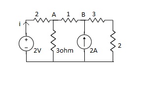
A6) Apply kcl at A
Va – 2 / 2 + Va / 3 + Va – Vb / 1 = 0
11Va – 6Vb = 6 ---(1)
Apply kcl at B
VB – VA / 1 + VB / 5 – 2 = 0
-5VA + 6VB = 10 ---(2)
From (1) & (2)
VA = 8/3V, VB = 35/9V
i = 2 – Va / 2 = -1/3A
Since, current leaves positive Terminal so, the element delivers power.
= -[ 2 x (-1/3) ] = -2/3
Or
Power absorb = 2/3 watts ( For voltage source )
For current source power delivered
= 35/9 x (-1/3)
= -70/9 watts
For any electrical circuit
Power delivered + Power absorbed = 0
-70/9 + 2/3 + power absorbed by ‘ R ’ = 0
Power absorbed by resistance = 64 / 9 watts
Q7) For the network below, the pole-zero pattern is represented in fig, find the numerical value of R, L, and c for z (0) =1?
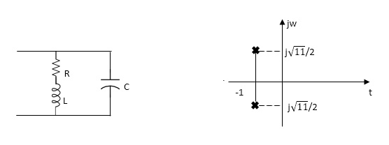
Fig Pole zero plot
A7) Calculating z(s) by taking L.T of fig 1)
z(s) = (R+SL)*1/CS
(R+SL)+1/CS = R+SL / SRC+S2LC+1
Z(S)= S+R/L / C [S2+R/L S+1/LC]
Given z(0)=1
z(0)=R/L / C/LC =1
Z(0)=R=1
.: R=1
Polls are given as
S2+RS/L+1/LC=0
S=-R/2L +J
Zeros are given as
S+R / L=0
From pole zero plot value of pole location is at -1 so
-R / L = -1
-1/ L=-1
L=1H
Also imaginary part of pole from plot is
 =
=
1/LC-(R/2L)2 =11/4
1/C-(1/2)2=11/4
1/C-1/4=11/4
1/C=11/4+1/4
1/C=12/4 =3
C=1/3 F
Hence, the value of R=1 L=14 and c=1/3 f
Q8) For the following circuits, FIND G12(S) =v2/v1
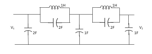
A8) Taking Laplace transform of above we have
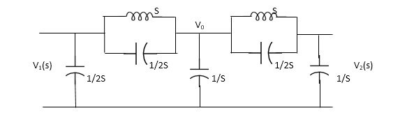
Fig Laplace Transform of the above circuit
Applying KCL at node v0
V0-V1(S) / S*1/2S/(S+1/2S) +V0+V2(S)/ (S*1/2S)/(S+1/2S)+V0/1/S=0
For Porr 2)We have ,
v2-v0/(s*1/2s)/(s+1/2s)+v2/1/s =0 ---------(ii)
(v2-v0)(2s2+1) / s +sv2=0
v2 [2s2+1/s+s] = v0( 2s2+1)/ s
v0=v2(3s2+1) / (2s2+1)-----------(iii)
From (i) we have,
(v0-v1) /s (2s2+1) *sv0+(v0-v2)/5 (s2+1) =0
(2s2+1/5)v0-(2s2+1)/sv1+sv0+(2s2+1)/sv0-(s2+1)/s v2=0
(2s2+1)v1=(5s2+2)v0-(2s2+1)v2
substitute value v0 from (iii) above
(2s2+1)v1 =[( 5s2+2)(3s2+1) /(2s2+1)-(2s2+1)]v2
(2s2+1)v1=(15s4+5s2+6s2+2-4s4+4s2) / (2s2+1 *v2
G12(s) = v2/v1 = (2s2+1) 2/11s4+15s2+1
Q9) Find the transfer function admittance ratio Y12(s) = I2(S) / V1(S)?

A9) Taking the Laplace transform of the above figure

Fig Laplace Transform of the above circuit
Applying KCL we get,
(V2-V1) / (3*1/2S) / (3+1/2S) * V2/ 1/2S+ V2/1/6 =0
(Y2-V1)(6S+1) / (6S+4) * (2S+6)V2V=0
BUT I2=-6V2
V2=-I2/6
We have,
(6s+1) / (6s+4)*v2-(6s+1) / (6s+4)*v1 +(2s+6)v2=0
-[6s+1 / 6s+s+2s+6]I2 / 6 =V1(6S+1) / 6S+4
-[6S+1(2S+6)(6S+4)]I2= 6(6S+1)V1
-[(6S+1)*12S2+36S+8S+24] I2=6(6S+1)
I2 / V1 =-6(6S+1) / 12S2+50S+25
Y12(S) = I2(S) / V1(S) = -6(6S+1) / 12S2+50S+25
Q10) Find whether the following network function represents the driving point function.
a) f(s)= (s+1)/(s2+1) b) f(s) = 3s2+2s+1/ss3+9s2+3s+2 c) f(s)=(s2+1)2/s2(s+3)
A10) a) f(s)=s+1/s2+1
It represents the driving point function:
b) F(S)= 3S2+2S+1 / 5S3+9S2+3S+2
It represents the driving point function.
b)F(s)=3s2+2s+1/5s3+9s2+3s+2
It represents the driving point function
c) f(s) = (s2+1)2/s2(5+3)
It has representative zeros, hence not valid
( s2+1)2=0
s2=+-1
s2=+-j,+-j
Q11) For the network shown, find driving point input impedance. Plot the pole zero pattern for each as well.

Fig Circuit Diagram (1) Circuit Diagram (2)
A11) For Fig (1) taking L.T we have
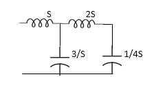
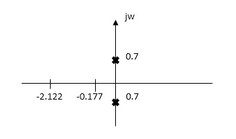
Fig Laplace for Fig (1) with roots
Z11= 1+ 1 /S/3+1/25+1/1/4S
=1+ 1/ 5/3+1/6S
=1+ 18S/6S2+3
Z11=6S2+3+18S/ 6S2+3 =2S2+6S+2/2S2+1
Zeros of equations are taking lt. of circuit b)
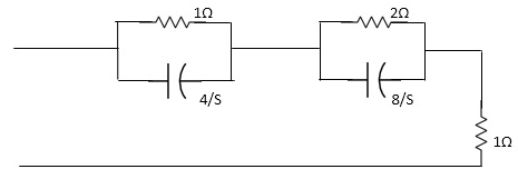
Fig Laplace for Fig (2)
Z11= 1*4/5
1+4/5+2.8/3/2+8/5+1
=4/5+4 + 16/ 25+8+1
= 4/5+4+8/5+4+1
=s+12+4/(5+4)
Z11= S+16/(S+4)
For zeros of system
s+16=0
s=-16
for poles of system
s+4=0
s=-4
