Unit - 1
Transformer Design: Part 1
Q1) A Cu bar 12mm in diameter is insulated with micanite tube which fits tightly around the bar and into the rotor slot of an induction motor. The micanite tube is 1.5mm thick and its resistivity is 8 ohm m. Calculate the loss that will pass from Cu bar to iron if temperature difference of 250C is maintained b/q them. The length of bar is 0.2 m.
A1)
Given – Diameter of Cu = 12mm = 12 × 10-3 m
Thickness of tube = 1.5 mm = 1.5 × 10⁻³ m
 8 ohm m ,
  = 250C
Length of bar = 0.2 m
To find: Qcon = ? = 

S =Perimeter = 

So, Ro =  ohm = 1.415 ohms
Qcon = 25/1.415 = 17.67 W
# Surface area is the extent of surface but the perimeter is continuous line that forms boundary.
Q2) The thermal resistivity of assembled armature laminations is 20 times as great along the direction of lamination as in the direction across the laminations. Calculate the loss that will be conducted across lamination in a stack 40mm thick and 6000 mm2 in cross section with difference of 20oC. Given that difference of 5oC will cause 25 W to be conducted through cross-section of 2500 mm2 in area and 20mm thick measured along the laminations.
A2)
It is given that:  = 20
= 20
Now, we have to find the loss that will be conducted across lamination. To find loss across lamination, we have to find value  along laminations.
Given data along the laminations-
Qcon = 25W  = 50C
= 50C
T = 20 mm = 20
S = 2500 mm2 = 2500  = 25
= 25 
So, Qcon = 
25 = 
So,  along direction of lamination = 0.025 ohm m.
Now, resistivity across lamination = 20  0.025 = 0.5 ohm m
Data across laminations
T = 40mm = 40 
S = 6000 mm2 = 6000  m2
m2
 = 0.5 ohm m
 = 20 0C

Qcon across lamination = 6W
Q3) A heat radiating body can be assumed to be spherical surface with coefficient of emissivity = 0.8.
The temp. Of body is 60oC and that of walls of room in which it is placed is 200C. Find heat radiated from body in watt per square metres.
A3)
e = 0.8 T1 = 273+60 = 333 K
T2 = 273+20 = 293 K
qrad == 5.7×10⁻⁸ e (T14 – To4) W/m2
= = 5.7×10⁻⁸ 0.8(3334 – 2934) = 224.6 W/m2.
Q4) A 250 V, 1 kW single element resistor is made from 0.2mm thick nickel chrome strip. The temp. Of strip is not to exceed 300oC over the ambient temp of 30oC. Calculate length and width of strip. Assume emissivity of nickel chrome 10-6 ohm m.
A4)
V = 250V P = 1000 W
Thickness, t = 0.2mm = 0.2×10⁻³ m
T1 = 300+30 = 330 oC = 330+273 K = 603 K
To = 30+273 = 303 K
e = 0.9×0.75 =0.675 [ ]
]
 = 10-6 ohm m.
To find - Length (l) width (w)
Now, we know that
qrad = = 5.7×10⁻⁸ e (T14 – To4)= 5.7×10⁻⁸ (0.675)(6034 – 3034) = 4762.53 W/m2.
Power =VI = V.(V/R)= V2/R
Let l =length of strip
t = thickness of strip
w = width of strip
A = cross section of strip


 ----------(1)
We know that
qrad =4762.53 W/m2 and also heat dissipated by radiation
Qrad = qrad (S) = 4762.53 (2)(wl)
So, 1000 = 4762.53 (2wl)
Lw = 0.1049 ---------------(2)
On solving 1 and 2,
l = 36.22m w = 2.89 m
Q5) A field coil has a heat dissipating surface of 0.15 m² and a length of mean turn of 1m. It dissipates loss of 150 W, the emissivity being 34 W/m² °C. Estimate final steady state temperature, rise of coil and its time constant if cross section of coil is 100×50 mm², specific heat of copper is 390 J/kg °C, the space factor is 0.56, copper weight 8900 kg/m³.
A5)
S=0.15m2
l=1m
Q=150W
 =34 W/m2oC
h = 390 J/kg oC
Wt. Of Cu = 8900 kg/m3
Cross section of coil = 100×50mm2
G=Volume×Density
Volume of Cu=1×100×50×10-6×0.56
Volume = 2.8×10⁻³ m3
Now, G=2.8×10-3×8900=24.92 kg

Heat time constant, Th = 
Q6) The exciting coil of Electromagnet has a cross-section of 120×50mm² and length of mean turn of 0.8 m. It dissipates 150 Watt continuously. It cooling surface is 0.125 m² and specific heat dissipation is 30 W/m² °C. Calculate the final steady temperature rise of coil surface, also calculate hotspot temperature rise of coil if thermal resistivity of insulating material used is 8 ohms m, the space factor is 0.56.
A6)
Temp. Rise of hotspot = 

Final steady temp. Rise of coil surface
 oC
oC
Now, temp. Rise between coil surface and hotspot

Here, q = heat produced/ unit volume
t = thickness


 = resistivity of insulation

Here,  = effective resistivity of winding (i.e. material + insulation)
 thermal resistivity of insulation
Sf = Space factor
 1/2)=2 ohm m
Final temp rise of coil surface and hotspot


Temp. Rise of hotspot =  m +
m + o = 40+19.5 = 59.50C
Q7) The temp rise of Xmer is 25°C after one hr and 37.5°C after two hours of starting from cold condition. Calculate its final steady temp. Rise and heating time constant. If its temp. Falls from final steady value of 40°C in 2.5 hr. When disconnected, calculate its cooling time constant. The ambient temp is 80°C
Note – Xmer starts from cold condition.
A7)
 1=25 oC
  2 = 37.5 oC
t1=1 hr t2 = 2 hrs.
Ambient temp. = 30 oC
Also, since Xmer starts from cold condition,
We use 
For 1 hr, 25  -----------------(1)
For 2 hrs., 37.5  ---------------(2)
Dividing 2 by 1
 -------------------(3)
 ,
,

1+  =1.5
=1.5
 =0.5
=0.5
Now,
25 =  (1-0.5)
 =50 0C
When cooling : cooling has started from final temp. Rise
T = 2.5 hrs
But still it is temp. Rise  =40-30 = 10 0C
 i(initial temp. Rise while cooling and final temp. Rise
  m)
m)
 i =
i =  m = 50
For cooling time,
 =
= i e-t/Tc
Tc = 1.55 hrs.
Q8) When initial temp. Of m/c is 45°C, calculate the temp. Of m/c after 1 hr, if final steady temp rise is 70°C and heating time constant is 2hrs. The ambient temp is 28°C.
A8)


Q9) The initial temp of m/c is 40°C. Calculate the temp of m/c after 1 hr. If its final steady temp rise is 80°C and heating time constant is 2 hrs, ambient temperature is 30°C.
A9)
Given initial temp = 400C
Initial temp rise = 40-30 = 100C


Temp rise after 1 hr.
θ=80(1-e-1/2)+10 e-1/2
=80-70 e-1/2
θ=37.54°C
Temp of m/c after 1 hr
=37.54+30 = 67.54 0C
Q10) The heat dissipating surface of 7.5 kW totally enclosed induction motor can be approximated as a cylinder of 0.6m in dia. & 0.9m in length. The motor can be considered to be made of homogenous material weighing 375 kg and having specific heat of 725 J/kg °C. The specific heat dissipation from its surface is 12 W/m² °C. Find temp rise of m/c at full load if efficiency is 90% and also find thermal time constant of machine.
A10)
Given Power o/p = 7.5kW = 7500 W
d=0.6m r=0.3m l=0.9m G=375kg h=725 J/kg oC
 W/m20C


Q11) A 1000 A shunt consists of 8 strips of nickel alloy connected in parallel each having cross section of (2.5×2mm²). The normal voltage drop is 75 mv. The alloy used has following data
Resistivity = 0.4 × 10⁻⁶ ohm m, specific heat 500 J/kg °C, specific gravity = 8000 kg/m³, rate of heat dissipation = 100 W/m² °C
Determine max temp rise and time taken to reach 99% of max value.
A11)
Ish = 1000 A
Cross sec area = 25×2 mm2 = 50 × 10-6 m2
V = 75 × 10-3 V


Let us suppose l is the length of each strip expressed in m.
Area of each strip
a = 50 mm2 = 50  10-6 m2

Now R for 8 strips in parallel

Voltage drop at shunt = 


Volume of 8 strips = 8(0.075)(50) 10-6 = 0.03
  10-3 m3
Wt. Of strip = Sp gravity  Volume
= 8000 0.03
0.03 -3 = 0.24 kg
Total heat dissipation surface
S = 8 2(l+b)h = 8
  2(2+25)
 10-6
10-6
=3.24  10-5 = 0.0324 m2
Th = 
Losses in strips
Q =  1000
1000 75
75 -3 = 75 W
Steady temp rise

As per given data, 99% of max value


Taking natural log


Q12) The exciting coil of an electromagnet has a cross section of 120×50mm² and a length of mean turn 0.8m. If dissipated 150W continuously, its cooling surface is 0.125 m² and SP heat dissipation is 30 W/m² °C. Calculate steady temp rise of coil.
A12)

Given a = 120×50 mm2
L = 0.3m 
Q = 150 W
S = 0.125 m2
 30 W/m20C
Q13) A 1527 A shunt consists of 10 strips of nickel alloy connected in parallel, each having cross sectional area 28×5 mm². The normal voltage drop is 100 mV. The alloy used following data:
Resistivity = 0.05× 10⁻⁷ ohm m
Specific heat 762 J/kg °C
Specific gravity = 7500 kg/m³.
Rate of heat dissipation = 200 W/m² °C.
Determine max terminal rise and time taken to reach 99% of max value.
A13)


WKT

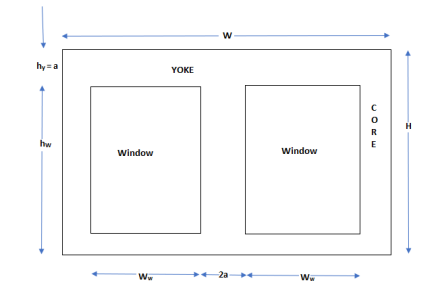
Design can be defined physical relaxation of theoretical concept. In design of Xmer o/p, is specified by uses, voltage rating, freq., no. Of phase are given by uses. But some parameters are selected by designer like type of cooling, type of core, etc.
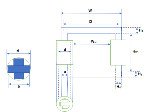
Overall heat, H = Hw + 2Hy
Overall width = D+a
Hy = a Aw = Hw.Ww
Ww = D-d
Q14) A 100 kVA, 2000/400 V, 50 Hz, 1 phase shell type Xmer has sandwich coils. There are 2 full HV coils, one full lv coil and 2 half lv coils. Calculate the value of leakage Reactance referred to HV side. Also calculate per unit leakage Reactance. The data given as
Depth of HV coil = 40 mm
Depth of LV coil = 36 mm
Depth of duct b/w Lv and HV = 16 mm
Width of winding = 0.12 m
Length of mean turn = 1.5 m
The no. Of turns in HV winding are 200.
A14)
Leakage reactance referred to HV side


Xp = 1.41 ohm
HV winding current at full load Ip = 
Per unit leakage reactance = 
Q15) A 300 kVA, 6600/400 V, 50 Hz ∆/Y 3 phase core type Xmer has following data
Width of hv winding = 25 mm, width of lv winding = 16 mm, height of coil = 0.5 m, width of duct b/w hv and lv winding = 15 mm, hv winding turns= 830.
Calculate leakage Reactance of Xmer referred to hv side, length of mean turn = 0.9 m.
A15)
Rating = 300 kVA
Voltage ratio = 6600/400 V
f = 50 Hz
bp = 25 mm bs = 16 mm
Lc = 0.5 m a = 15 mm
Leakage reactance referred to primary side


Q16) A 250 kVA, 6600/400 V, 3 phase core type transformer has total loss of 4800 W at full load. The transformer tank is 1.25 m in ht and 1m×0.5m in plan. Design a suitable scheme for tubes if average temp rise is to be limited to 35 oC. The diameter of tubes is 50 mm and are spaced 75 mm from each other. The average ht of tubes is 1.05 m.
So heat dissipation due to radiation and convection is respectively 6 and 6.5. Assume that convection is improved by 85% to provision of tubes.
A16)
Area of plane tank, St = 2(1+0.5)×1.25 = 3.75 m2
Let tube area be x.St
Total dissipating surface = 3.75(1+x)
Specific loss dissipation = 
From eqn of loss dissipated = 
Or x = 2.73
Area of tube = 2.73×3.75 = 10.23 m2
Wall area of each tube = 
=  = 0.165 m2
Total no of tubes = 10.23/0.165 = 62
Q17) What are the specifications of 3-phase transformer as per IS 2026?
A17)
Oil Natural Air forced (ONAF)
In this method the oil circulating under Natural head transfers heat it to the tank walls. The Transformer tank is made hollow and air is blown through hollow space to cool the Transformer. The heat removed from inner tank walls can be increased to 5 or 6 tines that dissipated by natural means and therefore very large Transformer can be cooled by this method.
Oil natural water forced (ONWF)
In this method, copper cooling coil are mounted above Transformer core but below surface of oil. Water is circulated through the cooling coils to cool the Transformer. This method proves to be cheap where natural water head is already available. This method has serious disadvantage that it employs a cooling system which carries water inside the oil tank. Since water is at Higher head then oil, therefore in case of leakage water in cooling tubes will enter Transformer tank contaminating oil and reducing dielectric strength. The water inlet and outlet pipes are left in order to prevent moisture in ambient air from condensing on pipes and getting into the oil.
Forced circulation of oil (OF)
In large Transformers, natural circulation of oil is insufficient for cooling the Transformer and forced circulation is employed. Oil is circulated by motor driven pump from top of Transformer tank to an external cooling plant where oil is cooled. The cold oil enters Transformer at bottom of the tank.
Now, this method of cooling oil in heat exchangers (external cooling plant) depends upon condition obtained at the site. This method of cooling Transformer by forced circulation are classified as-
1) OFAN (oil forced air natural)
2) OFAF (oil forced air forced)
3) OFWF (oil forced water forced).
- Oil immersed Transformer of rating upto 30 KVA use plain walled tank. Above 30 KVA heat dissipating capacity of transformer is increased by providing corrugation, tubes and radiator tank.
- Transformer up to 5 mva or 50 KW use tank with tubes. The tubes are usually round and 55 mm and are arranged in one of three rows, elliptical tubes are used.
OFAN – Oil is circulated through the Transformer with the help of pump and cooled in heat exchanger by natural circulation of air. This is not commonly used. However this method proves very useful where cooler have to be well removed from transformer.
OFAF
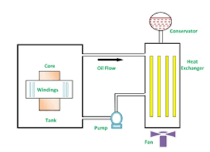
The oil is cooled in external heat exchangers using air blast produced by fan. It is interesting to note that the oil pump and fan may not be used all the time. At low loads, losses are small and hence natural circulation of oil with an ONAN condition may be sufficient to cool the Transformer.
At Higher loads, the pump and the fans may be switched on by temperature sensing elements.
Hence, Mixed cooling conditions are used, transformer working with ONAN conditions upto 50% of rating and OFAF conditions at higher loads. This arrangement results in increase of efficiency of systems.
OFWF – In this method, the heated oil is cooled in water heat exchanger. The pressure of oil is kept higher than that of water and therefore any leakage that occur is from oil to water.
This cooling method is suitable for banks of Transformer but from the system reliability consideration not more than three times should be connected in one cooling pump circuit. The advantage of OFWF method over ONWF are that the transformer is small and Transformer tank does not have to contain cooling coil carrying water. The use of water as coolant is common at generating stations, particularly hydro-electric stations where large supply of water is available. The OFWF is used for transformer design for hydroelectric plants.
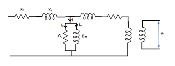
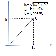
A transformer is said to be no load when its secondary winding is open circuited ie nothing is attached and Transformer loading is zero. When AC is connected to primary winding of transformer, a small current Io will flow through primary coil winding due to presence of primary supply voltage. Since secondary is open, a back EMF along with primary winding resistance act to Limit flow of this primary current. This Io (no load primary current) is made of following two components-
1) IE (in phase current) which supplies core losses (eddy current and hysteresis)
2) Im at 90° to voltage with sets up magnetic flux.
Q18) How the transformer tanks are designed to overcome the increase in temperature?
A18)
Because of losses in transformer, the temperature of Core and coil increases. In small capacity Transformer the surrounding air will be in position to cool the Transformer effectively and keep the temperature rise within the permissible limits.
But as the capacity of Transformer increases the loss and temperature rise also increases. This it is not advisable to use atmospheric air for cooling. To overcome this problem transformer is placed in steel tank filled with oil. The oil conduct heat from core and coil to the tank wall. Then heat dissipated in surrounding due to radiation and convection.
Temperature rise in pain walled tank
The walls of tank dissipates heat by both radiation and convection. It has been found experimentally that tank dissipates 6 and 6.5 w/m² °C by radiation and convection respectively. Thus, the total loss dissipation is 12.5 W/ m²°C.
Temp rise 
The surface to be considered in a formula is total area of vertical side + one half of area of cover unions oil is the contact with cover in which case whole area of lid should be taken. The area of bottom of tank should be neglected as it is very little cooling effect.
For transformer of low o/p, plain walled tank are large enough to accommodate the Transformer and oil have sufficient surface to keep temperature rise within limit. But for transformer of large o/p, plain walled tank are not sufficient to dissipate losses because increase in rating increase loss to be dissipated per unit area giving higher temperature rise.
For transformer for larger o/p must be provided with means to improve the condition of heat dissipation. This may be done by providing tubing or radiators where feasible.
Path of heat flow within Transformer by way of radiation and convection is as follows:
1) From internal most heated spot of given path i.e. winding or core to outer surface in contact with oil (heat is transferred by conduction)
2) From outer surface of given Transformer to the oil that cools it (heat is transferred by Convection of oil).
3) From coil to walls of cooler for instant of tank. (again heat is transferred by Convection of oil).
4) From walls of cooler to the cooling medium i.e. air or water (heat is dissipated by both Convection and radiation).
Temp rise and design of tank with tubes
Let dissipation surface of tank = St
It will dissipate (6+6.5) St = 12.5 St W/°C
Let area of tubes = xSt -----------------(1)
Loss dissipated by tubes by convection =1.35×6.5xSt = 8.8x St W/oC
So, total loss dissipated by tank and tubes = 12.5 St + 8.8xSt = St (12.5+8.8x) W/oC
Total area of tank and tubes = St + xSt = St (1+x)
Hence, Sp heat dissipation by tank and tubes =
Temp rise with tubes, 

Total area of tubes = xSt = 
Let lt and dt be length and dia of each tubes respectively.
So, area of each tube = 
Hence, no. Of tubes nt
Area of tube can be found by using above expression.
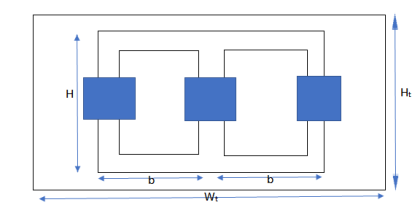
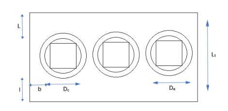
Width of tank
Wt = 2D+De+2b (for 3 phase)
= D+De+2b (for 1 phase)
Where D = distance between adjacent limbs
De = external dia of hv winding
b = clearance b/w hv winding and tank.
Length of tank Lt = De+2l
l= clearance on each side b/w winding and tank along width.
Ht. Of Xmer tank Ht = H+h
Hheight of Xmer frame
hclearance ht. b/w assembled.
Typical values of clearance b,l and h are
Voltage | Rating | Clearance B l h |
11 kV or less | Less than 10000 | 40 50 450 |
About 11KV | 1000-5000 | 70 90 420 |
Upto 33 kV | Less than 1000 1000-5000 | 75 100 550 85 125 550 |
Q19) Derive the expression for leakage reactance of core type transformer?
A19)
Leakage Reactance of Core type Transformer
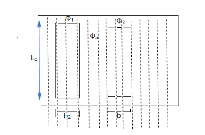
Three leakage flux paths are shown.
Let
 Leakage flux in primary and secondary windings.
 flux through duct
Lomean circumference of duct
Lcaxial height of windings
bp, bs radial width of primary and secondary winding respectively
aWidth of radial duct.
The flux leakage of windings can be found under:
a) conductor portion
b) duct portion.
Conductor portion-
Consider extremely small strip of width dx at a distance x from the edge of primary winding along its width.
Mmf acting across strip =
Permeance of strip =
Leakage flux in the strip = 
This flux links with=
Hence,flux linkage of primary due to strip =
So,


Hence flux linkages of primary winding due to flux in the strip.

Integrate both side


Duct portion-
Mmf acting across duct = IpTp
Permeance across duct =
Flux in duct= Ip Tp
Ip Tp
Duct flux linking with primary winding =  (
( Ip Tp)
Since ½ of duct flux links with primary and secondary winding respectively
= (
( Ip Tp)
Above flux links with entire primary winding.
Hence, flux linkage of primary due to duct flux

Hence, total flux linking of primary winding


Assume 

Leakage inductance of primary winding

For leakage reactance of primary winding
XL = WL =2
Xp =XL = 2
Similarly, leakage inductance of secondary winding can be calculated
Xs = = 2
Leakage reactance of secondary winding referred to primary side


Total reactance of Xmer per phase referred to primary side
Xp = Xp +Xs’

And per unit reactance

As WKT
IpTp = AT Vp/Ip = Et

In some cases-
- When transformer is on no load, all the flux produced by primary coil passes through the core. In other words, all flux produced by primary coil links with secondary coil and so there is no drop of voltage or no load.
- But when transformer is on load, because of load current flowing in both in secondary flux will produce independently by two coils. Depending upon value of current primary and secondary coil will both develop their corresponding fluxes in air. From total flux produced we have to find out which is leakage flux. It is this leakage flux which cause EMF to be induced in the coil which appears as reactive voltage drop in them.
- More the current, more is the leakage flux and so also reactive drop.
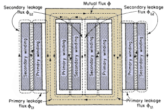
Three leakage flux paths  are shown
 leakage flux in primary and secondary winding
 flux through duet
Lo mean circumference of duet
Lc axial height of windings.
Q20) Explain the construction of transformer core and materials required?
A20)
Construction of Xmer core and material
In all type of Xmer, core is constructed of sheet steel lamination to provide cont. Magnetic path with minimum of air gap included.
The steel is used is of high silicon content.
Eddy current losses is minimised by laminating the core. Laminations are insulated from each other by light coat of core plate varnish or by oxide layer on surface.
The thickness of lamination varies from 0.35-0.5 mm.
Main problem with Xmer core is
1) Hysteresis
2) Eddy current losses.
Hysteresis loss in Xmer depends on the core material.
It is found that small quantity of silicon alloyed with low carbon content steel produced material for Xmer core, which has low hysteresis loss and more permeability with less magnetising current.
With more demand on power it is required to further reduce core losses and for that more technique is employed on steel which is known as cold rolling.
This technique arranges the orientation of grain in ferromagnetic Steel in direction of rolling.
The core steel which has undergone through both Silicon alloy and cold rolling treatment is known as CRGOS or cold rolled grain oriented Silicon Steel. This is universally used for manufacturing Transformer core.
Hot rolled Steel permitted maximum flux density of 1.45 Wb/m² where as cold rolled Steel allows 1.8 Wb/m² flux density.
In both Core and shell type transformer, individual laminations are copper in form of long strips of Ls, Es and Is.


Core cross section
Small core type transformer have rectangular section limbs with rectangular coil as shown below.
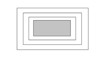
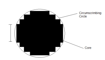
But for large size Transformer it becomes wasteful to use rectangular cylindrical coils. However economic use of Core material required cross section of core should ideally be circular. Since circle has minimum Periphery for particular area and hence winding which put around the core has minimum length of main turn resulting in reduced amount of conductor material thereby reducing cost.
But circular core however in involves use of unmanageable large number of laminations of different sizes which is possible but is highly time-consuming and also uneconomical.
Now also considerable amount of useful space is wasted. So common improvement on square core is to employ cruciform core which demands at least two sizes of core strips.
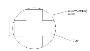
For very large Transformers for the course testing is done where at least three size of core plate are necessary.
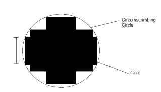
Core Stepping not only gives high space factor but also results in reduced length of mean turn and consequent power loss.
3 stepped core is one of the most commonly used all the more steps may be used for very large Transformers.
