Unit - 3
Performance parameters of Transformer
Q1) Determine the dimension of core and take for a 200 KVA ,50 Hz 1 core type. A cruciform core is used with distance between adjacent limbs equal to 1.6 times the width of core Laminations. Assume voltage per turn 14 V maximum flux density 1.1
  window space factor 0.32 current density 3
  & stacking factor =0.9 The net iron area is 0.56
  in cruciform core where d is the diameter of circumscribing circle also the width of largest stamping is 0.85
A1)
Q=200KVA
F=50 Hz
Core=cruciform
D=1.6a
.
. W6/
W6/
Kw=0.32
.
S,F,=0.9
 =0.56
=0.56
a=0.85d
Voltage per turn 
=
Net iron area =
=

Diameter of circumscribing circle

 =
= =0.32m
Width of largest stamping
A=0.85d
=0.85*0.32
a=0.272m
Distance between core centres D=1.6 a
=1,6*0.272
D=0.435 m
Width of window =D-d
=0.435-0.32
=0.115m
For 1 

=0.732

 14.64V


 0.0777

AT=27500A


 0.0298
Height of window  =0.26m
Depth of yoke =a=0.272m
Height of yoke =0.272m
Overall height of frame 
H=0.804m
Overall Length of frame = D+a
=0.707
Q2) The ratio of flux of full load mmf is 400KVA,50Hz 1  core type is
  Calculate net iron area & window area maximum flux density in core is 1.3
 current density 2.7 window space factor is 0.26 Also calculate full load mmf
A2)
Given
Q=400KVA B=1.3
Voltage per turn 
Q3) A 1 400 V 50Hz is built from stampings having a relative permeability of 1000. The length of flux path is 2.5m the area of cross sectional of core is 2.5*
  & the primary winding has 800 turns Estimate the max flux and no load current. The iron loss at the working flux density is 2.6W/Kg Iron weight
  .Stocking factor is 0.9
A3)
Given that
 f=500Hz S.F=0.9
  2.5m
2.5m


Iron Density =
We know that


=

=
=
Now Maximum flux =

Magnetizing mmf
 =Reluctance *Flux
=
=
=
=
 =1989.43A
Magnetizing current

 =1.75A
We know that 

To find P:- Iron loss per Kg *Weight of core
Volume of core =Flux in core *length of flux path
=
=
=
Now Weight of core =Volume of core *Density of core
=43.8 Kg
Iron Loss =iron loss per kg *weight of core (Total Kg)
=2.6*43.8

Now loss component of no load current =

No load current 
=

Q4) A 6600 V, HZ 1 has a core sheet steel the net iron crosses area is 22.6*
 ,the mean length is 2.23m, there are 4 lap coins. Each cap joints taken ¼ times as much reactive mmf as is required per meter of core .if Bm=1.1 w6/
 detertime
- No. Of turns of 660 V winding
- No load current
- Assume amplitude factor of 1.52 & that of given flux density mmf per meter =232 A/m specific loss= 1.76 w/kg specific gravity =7.5
A4)
Given:
E=660V
f=60Hz 
 2.23m
2.23m

Amplitude factor=1.52 
Specific Loss =1.76W/Kg
Specific Gravity=
a> T or N =
=
T=996

Total magnetizing MMF ( )=MMF of iron parts +MMF of joints
MMF of iron parts =
MMF per meter length *Mean length
=232*2.32
=517AT
MMF of joints =MMF/meter length
=232A
So total magnetizing MMF=517+232
=749A

=

Total iron loss =iron loss per kg*weight of core
Weight of core =Volume *Density
=378Kg
 =1.76*378
=665W


=0.33A
Q5) A 6600V,50Hz 1 has a core of sheet steel. The net iron cross sectional area is
  the mean length is 2.23m & there are 4 joints each joint taken
  times as much reactive MMF as is required per meter of core. If
  determine
a> Number of turns on 6600V winding &
b> The no load current
Assume an amplitude factor of 1.52 & that for given flux density, MMF per meter =232A/m, Specific iron Loss = .Specific gravity of plates =7.5
A5)
Given
 f=50Hz
Amplitude factor=1.52 
MMF/meter=232A/m 
SP iron loss=1.76W/Kg SP gravity =7.5
4 lap joints

We know that 


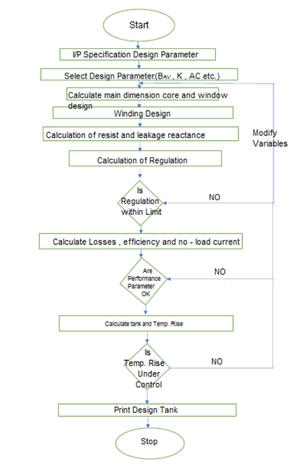
Q6) Explain CAD and flow chart of computer aided design of transformer?
A6)
Introduction to Computer Aided Design of Induction Motor
- The design of electronical m/c consists essentially solution of many complex & diverse engineering problem & normally there problems are interrelated to a greater or lesser degree
- The manual design procedure of m/c is time consuming needs more manpower & further more accuracy level may be lower
- There are various design which are computer Aided design
- Analysis Method: Computer is used only for purpose of analysis only & all decision are taken manually by designs
- This method the choice of basic parameters & types of construction are done by the design only
- There are given as I/P to the computer for estimation of different M/C dimensions &performance calculation
- The performance calculation is the critically examined by designer can make other suitable choice of parameter to re calculate the performance
- If the design is satisfactory the o/p given is the final design
- The process is repeated till performance calculatedly are satisfactory.
Synthetic Method of Design
The logical decision is taken by the computer
- Logical decision includes the suitable change in parameter of achieve desired design &performance
- Logical decision includes the suitable change in parameter to achieve desired design &performance
- As analysis &decision both are taken by computer time required for calculate is reduced
Hybrid Method
- When both analysis & synthetic method is used simultaneously then this is called hybrid method.
- Here the logical decision is partly taken by the designers and partly by computer
- By using both the methods together means that computation work can be largely be done by computer programmer
- Same decision must be taken by the designer which will reduce the complication of design program
Generalized Flow Chart of Design
Q7) Derive expression for calculation of mechanical forces
A7)
Radial forces
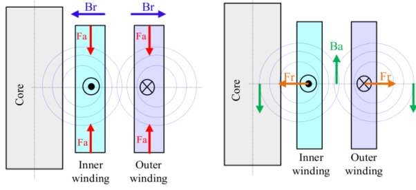
Consider core type with cylindrical winding as above in figure
The winding has ‘T’ turns &carries an instantaneous current ‘I’ the instantaneous MMF acting the duct is iT.
The flux density of duct is

H is intensity which is A/m

As Flux density in winding varies from 0 to 
Average flux density in duct
As per assumption during leakage flux in winding says that half of the leakage flux in duct links with each of the winding


Now assuming  &
& =1
=1

Taking a small strip at mean radius R with in an angle  of coil
The force acting on the strip is  & calculated as
 =Number of turns *Flux density *current *Length of strip
=
=
 -------1
Total instantaneous radial force acting on coil is

=
=
But  =Mean periphery of coil
 --------2
Now average radial force under normal condition
From equation 1

=
As 
=
= 
We know that

=
=
=
=
=
 ------------3
Maximum radial force on worst condition 
On worst fault condition the instantaneous value of current may become equal to twice the maximum value of current under short circuit condition

On worst fault condition
I=RMS value of full load current
 =Per unit leakage reactance & resistance is neglected.
Maximum radial force from equation 2


Ratio of maximum force to normal force is

=
So it is clear that radial force is inversely proportional to square of P.V. Reactance.
The winding must be designed to with stand radial force under worst fault conditions.
It is clear that circular coils should be preferred as they are strongest to withstand radial forces
This is because tendency of radial forces is to make coils circular and as they are already circular there is no deformation However if rectangular or square coils are used they would be deformed by radial forces.
In shell type the coils are rectangular but these coils are mechanically braced for a considerable part of their length & hence are mechanically strong.
Q8) Derive expression for calculation of axial forces
A8)
Axial Forces
The winding current interact with radial component of leakage flux to produce axial compressive forces tending to squeeze winding together in middle with symmetrical winding these forces are not noticeable even at short circuit. In shell type having sandwich coil symmetrical arrangement there is force of repulsion between coils
Average value of this force 
Measures to overcome the effect of material forces
To overcome the problem of mechanical forces circular coils are used for winding as they can with stand the radial forces {in circular coil radial forces are cancelled by each other & wherever it is not possible to use circular coil {example shell type} they should be braced properly. In shell type though coils are rectangular they are mechanically strong as larger portion of coils is mechanically braced.
Apart from bracing a good quality of insulation (electrically as well as mechanically strong) should be used coils should be supported & braced by taking into consideration of mechanical stresses
The power is designed to have high leakage reactance which reduces magnitude of short circuit current during fault Hence reduces mechanical forces
When I increase Leakage magnetic flux in winding increases & magnetizing flux in core increases therefore forces in winding will increases increase B & increase Leakage flux provides very big force in winding
Q9) Calculate mechanical forces developed under short circuit conditions?
A9)
Mechanical Forces Developed Under Short Circuit Condition.
Mechanical forces or stresses exist in an ordinary because of interaction between the current in the winding and the stray magnetic field which sour rounds them.
It is well known that 11 conductor repel or attract each other according to whether the current they carry are in the opposite or in same direction
Under ordinary or normal situation the current is small. The forces are moderate & are not sufficiently large to be noticeable
But under short circuit conditions at full voltage the short circuit current may reach 10 to 25 times full load value with mechanical forces 100 to 625 times the normal.
Under such conditions the mechanical force may become so great as to wreck the coils are solidly braced.
The forces produced may be analyzed in three components
1. Radical forces
2. Axial forces
3. Forces due to asymmetry
Note
The two winding carry current in opposite direction
Q10) Explain axial and radial leakage fields producing radial forces?
A10)
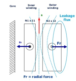
Leakage field in core type is shown in figure. This leakage field is resolved into axial & Radial component
Radial Forces (due to axial field)
Inner winding near to core experience radial forces which are going to shrink the winding to core were as outer winding experience forces which are going to expand it
Axial Leakage Field Producing Radial Forces
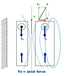
Above figure shows the interaction of the axial component of leakage flux with current carrying windings
Applying Fleming’s Left Hand rule it is known that force acts in radial direction
The nature of radial force is such that it tries to burst the outer winding (due to tensile force) & to crush the inner winding (due to comprehensive force)
This is obvious because the primary & secondary winding of carry current in opposite direction and therefore produce a force of repulsion tending to pull the outer winding & to compress inner winding (due to conductor of same winding)
Axial Forces: Axial forces are the forces which are between different branches of same windings are going to carry current in same direction. Forces acting between the conductor are attracted so they are going to shrink the windings
Above figure shows the interact of radial component of leakage flux with the current carrying winding
Applying Fleming left hand rule it is found that forces produced due to this interaction act in axial direction
The forces acting on winding in axial direction are compressive in nature However if there is an axial magnetic asymmetry between two winding a tensile force is produced.
The magnitude of force acting in a conductor is proportional to product of current in it & intensity of magnetic field due to current in neighboring conductor & the latter itself is proportional to current the “Forces are proportional to square of current “.
Q11) Calculate the voltage regulation of transformer?
A11)
V.R indicates the change of secondary terminal voltage from no load to load conditions, Keeping primary voltage constant
Consider a simplified equivalent circuit for lagging load with parameters referred to primary side.

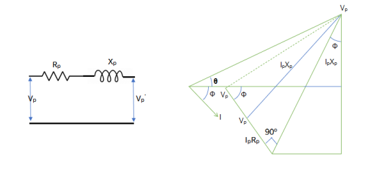
On no load secondary terminal voltage

From phase diagram we can write


Assuming the angle( between
  &
& is very small we have


Per unit regulation is given by


 =Per unit resistance
 =Per unit reactance
Hence by knowing the value of  &
& the value of per unit can be found over V.R. Should be low
Q12) Explain the procedure to calculate all types of losses?
A12)
Procedure to calculate core losses in:
In the design process the core losses are not calculated from hysteresis loss& eddy current loss bat are estimated using graph of flux density V/S cross per kg & weight of iron.
Core consist of limbs & yoke. The losses are not calculate separately & added to get total core losses.
Core losses in limbs:
Core losses in limbs =Weight of limbs  Sp of iron losses(Kg)
To calculate specific iron loss it will be calculated by B-H curve
For weight of limbs (Kg)=Volume *Density of iron
For volume =
=
Where, = Mean length of flux path through limb
 Net iron area
Core losses in yoke:
Core losses in yoke =Weight of yoke *Sp iron loss (usually it is calculated from the B-H curve
Weight of yoke =volume *Density of iron (it is always  for iron )
For volume =
 =mean length of flux path through yoke
 =Net iron area
So total core loss is given by
Total core loss =Core losses in limbs +core losses in yokes
Estimation of efficiency
Efficiency =
& Losses =Total CU losses +Total core losses
Q13) What the copper and core losses and estimate all the losses?
A13)
Commonly there occurs two main types of losses i.e.-
1. Copper losses  loss]
loss]
2. Core losses [ iron losses]
- Cu losses
 loss]
loss]
These are the losses taking place in the conductor of cu is the most commonly used conductor. The losses are generally referred as cu losses.
The cu losses are due to power wasted in the conductor the losses are due to the resistance of primary and secondary winding.
The losses depend on the magnitude of current flowing in the winding as well as resistance of primary & secondary winding.
As the current depends upon the load &load keeps on changing these losses changes and hence they are called as variable losses.
Total cu losses Is addition of cu losses in primary and cu losses in the secondary winding
No load current

We know that


=

=232*2.32
=517.36A

=4 *232
*232
=232
 =577.36+232
 749.36A
Magnetizing current 
 Peak factor) =Amplitude factor *
 =1.52*
 =2.15
=2.15
 =8.318A
Weight of core =2.23*22.6*7.5
Total iron loss =1.76*378
=665W
Loss component  =0.1A
=0.1A
No load current 
=0.3333A
Q14) Estimate the leakage reactance of transformer?
A14)
Leakage Reactance
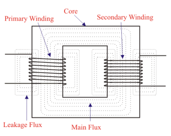
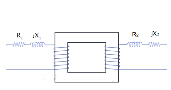
In practical, small portion of flux will link with either of the winding but not with both. This is known as leakage flux due to this leakage flux here is self reactance in concern winding. This self reactance is known as leakage reactant. This leakage reactant associated with resistance is known as impedance due to this impedance there will be voltage drop in primary and secondary windings.
In ideal resistance is considered to be zero .so, no leakage reactance and core flux link with core but practically it is not possible.
Window Dimension
If D is small,  is limited and this must be counter balance by increasing height of window. Thus winding are long and thin which result in low value of leakage reactance
If height of window is limited has to increase in order to accommodate coil this results in short and wide coils giving large value of leakage reactants
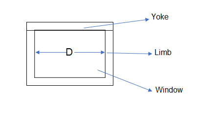
Overall Dimensions
When dealing with overall dimensions thus problem refers to following details and diagram
a=width of largest stamping
d=diameter of circumscribing circle
D= distance between centers of adjacent limbs
 =width of window
 =height of window
=length of limb
 =height of yok
 = depth of yok
H=overall height yoks or overall height of frame
W=length of yoke
=overall length of frame or width
From diagram
1.for  core type


Width over 2 limb =D+ outer diagram of HV winding
Width over 1 limb =Outer diagram of HV winding
For 3 core type


Width of 3 limbs =2D +outer diameter of HV winding
Width of 1 limbs =outer diameter of HV winding
For 1 shell type


Q15) List the steps for design of reactance?
A15)
Simplified Steps for Design
Steps for determinate of main dimensions for core window & yoke
Step 1 Calculate voltage per turn using formula
 volts
volts
K=Value from table given after volt /turn
Also 
Step 2 Find net cross sectional area of the core  from the equation


Where 
Step 3 Determine the diameter of the circumscribing circle using formula

Where, 
Step 4 find the width of window from equation

Step 5 Obtain window area from equation
For1 


For 3 


Step 6 find height of window as

If d is not given then first  is calculated using step 5 instead of step 4 .Thus we use the concept that usually ratio &
 =
=

Thus height of window  is obtained
  hence with known values of
  &D we can find d
Step 7 Obtain depth & height of yoke for stepped core using formula
 ,
,
Here a= width of largest stampings
Step 8 Obtain overall height and length of the frame
For 1  core type
 ,W=D+a
For 3  core type
 ,W=2D+a
For 1 , shell type
 ,W=2
,W=2 +4a
+4a
In case a is not given, we assume 0.9d instead of a in above equation for stepped core 0.85d for cruciform & 0.71d for square core
Step 9 Design of HV& LV winding (which has been already discussed & the same has to be written here