Unit I
Basic Circuit Analysis and Simplification Techniques
Kirchhoff Current Law:
A node is a circuit connection that extends to all its neighboring elements but does not contain them.
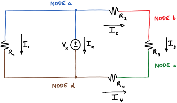
Kirchhoff’s current law states that at a node:
Sum of the in currents = sum of out currents
Applying KCL at four nodes
0 = Ix + I1 + I2 KCL at node a
I2 = I3 KCL at node b
I3 + I4 = 0 KCL at node c
Ix + I1 = I4 KCL at node d
Adding equations 6-9 gives the following equation:
Ix + I1 + I2 + I3 + I4 = Ix + I1 + I2 + I3 + I4.
Kirchhoff Voltage Law:
A loop is a path around a circuit that starts and ends in the same place.
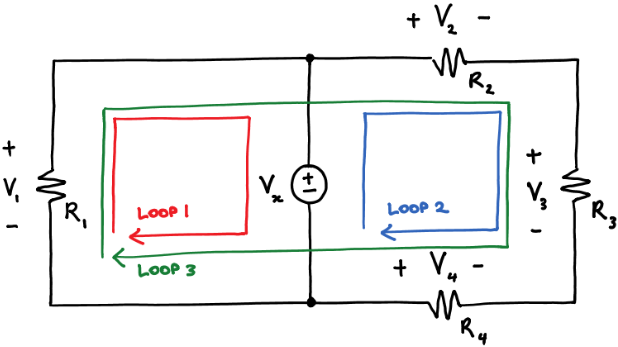
Kirchhoff's voltage law (KVL) states that around a loop:
sum of voltage rises=sum of voltage drops--------------------(1)
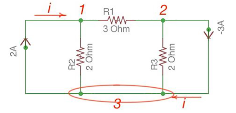
Applying KVL around the three loops we get
V1 = Vx KVL around loop 1
Vx + V4 = V2 + V3 KVL around loop2
V1 + V4 = V2 + V3 KVL around loop3
2.Find out V1 and V2 using KVL.
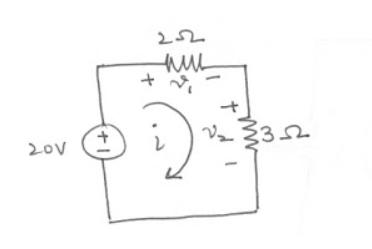
-20 + v1 + v2 =0 ------------------------(1)


 V1 = 2i from the circuit
 V2 = 3i
Therefore
-20 + 2i + 3i =0
5i = 20
i=4A
v1 = 2i = 2(4) = 8V
v2 = 3i = 3(4) = 12V
3.Explain independent and dependent sources?
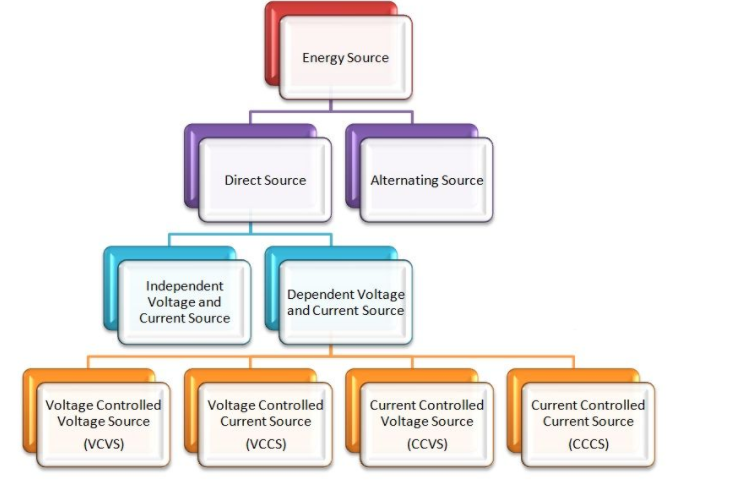
The Independent and Dependent source means, whether the voltage or current sources are either depending upon some other source, or they are acting independently.
Energy Sources
There are two types of energy source direct sources and alternating sources.
Direct Source
The voltage and the current source are the direct sources. The direct source is further classified as independent voltage and current source and dependent voltage and the current source.
Independent Voltage and Current Source
Independent sources are that which does not depend on any other quantity in the circuit. They are two-terminal devices and has a constant value, i.e. the voltage across the two terminals remains constant irrespective of all circuit conditions.
The strength of voltage or current is not changed by any variation in the connected network the source is said to be either independent voltage or independent current source. In this, the value of voltage or current is fixed and is not adjustable
Dependent Voltage and Current Source
The sources whose output voltage or current is not fixed but depends on the voltage or current in another part of the circuit is called Dependent or Controlled source. They are four-terminal devices.
When the strength of voltage or current changes in the source for any change in the connected network, they are called dependent sources. The dependent sources are represented by a diamond shape.
The dependent sources are further categorised as:
Voltage Controlled Voltage Source (VCVS)
In voltage-controlled voltage source, the voltage source is dependent on any element of the circuit.
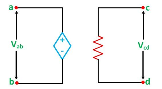
In the above figure, the voltage across the source terminal Vab is dependent on the voltage across the terminal Vcd,
Vab α Vcd or
Vab = k Vcd
Voltage Controlled Current Source (VCCS)
In the voltage controlled current source, the current of the source iab depends on the voltage across the terminal cd (Vcd) as shown in the figure below:
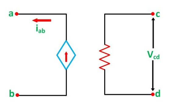
iab α Vcd
iab =  Vcd
Vcd
Thus,
Where ƞ is a constant known as transconductance and its unit is mho.
Current Controlled Voltage Source (CCVS)
In the current controlled voltage source voltage source of the network depends upon the current of the network as shown in the figure below
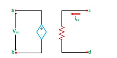
Here the voltage of source Vab depends on the current of the branch cd
Vab α icd
Vab = r icd
Where r is a constant.
Current Controlled Current Source (CCCS)
In the Current Controlled Current Source, the current source is dependent on the current of the branch another branch as shown in the figure below
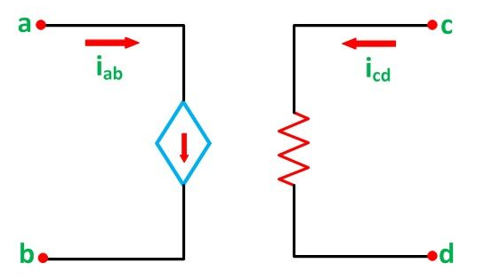
iab α icd
iab = β icd
So,
Where β is a constant
4. Explain Power calculations ?
Power Formula 1 – Electrical power equation: Power P = I × V = R × I2 = V2 ⁄ R
where power P is in watts, voltage V is in volts and current I is in amperes (DC).
If there is AC, look also at the power factor PF = cos φ and φ = power factor angle
(phase angle) between voltage and amperage.
Electric Energy is E = P × t − measured in watt-hours, or also in kWh. 1J = 1N×m = 1W×s
Power Formula 2 – Mechanical power equation: Power P = E ⁄ t where power P is in watts,
Power P = work / time (W ⁄ t). Energy E is in joules, and time t is in seconds. 1 W = 1 J/s.
Power = force multiplied by displacement divided by time P = F × s / t or
Power = force multiplied by speed (velocity) P = F × v.
5. Explain Mesh and Super mesh?
Mesh Analysis:
Mesh analysis is applicable to the networks which are planar. Planar network is a network where branches are not passing over or under each other.
Nodal method uses Kirchhoff’s currents Law to consider nodal voltages, and Mesh method uses Kirchhoff’s voltages Law to consider mesh currents. Mesh is a loop, which does not contain any other loops.
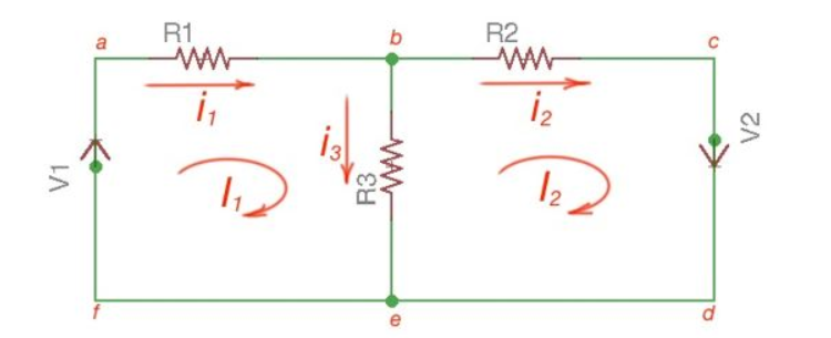
There are only two meshes in abefa and bcdeb, abcdefa is not a mesh but a loop However, for Mesh method only meshes are in use.
Mesh analysis steps are the following:
The following equations correspond to the Kirchhoff’s Voltage Laws for the meshes:
V1 = i1 *(R1+R3) – i2 *R3
-V2 = -i1 *R3 + i2 * (R3 +R2);
[ R1 +R3 -R3 [i1]= [V1]
-R3 R2+R3] [i2] = [V2]
Using Cramer’s formula for resolving the matrix equations above we can find mesh currents.
I1 =i 1 I2 = i2 I1 -I2 =i3
Super Mesh Analysis
A super-mesh is a larger loop which has both meshes inside.
There are two methods.
1) Using 

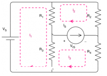
Mesh II:
R1 x (I2 – I1) + R2 x (I2) – V IS =0
Note that for R1, unlike the equation for Mesh I, the current is I2 – I1. This is because we are walking around the loop with the direction of I2, or briefly it is because we are writing the equation for mesh of I2.
Mesh III:
R3 x (I3 – I1) + VIS + R4 x (I3) =0
Let's add two equations:
R1 x (I2-I1) + R2 x (I2) – VIS + R3x (I3 -I1) + VIS + R4x(I3) = 0+0
Simplifying:
R1 x (I2-I1) + R2 x (I2) – VIS + R3x (I3 -I1) + VIS + R4x(I3) = 0+0
Method -II
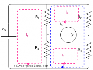
Here is the supermesh: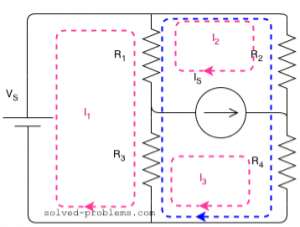
Around the loop clockwise:
R1 x (I2-I1) + R2 x (I2) + R4 x (I3) + R3 x (I3 – I1 ) =0
As you can see, we were able to write the equation in one shot. That is why the supermesh method is preferred.
6. Explain node and super node analysis?
Nodal analysis
In the nodal method we are finding the node voltages with the following steps:
Consider the following circuit.
Let us consider a reference node – 3.
In a real circuit a reference node is ground is assumed to have potential.
By the Kirchhoff’s Law having the following current relation:
I1 = i1 + i2
I2 = i2 -i3
Let us represent currents like ratio of voltage and resistance by the Ohm’s Law:
i 1 = v1 /R1 ; i 2 = v1 -v2 /R2 ; i3 = v2/R3;
or
i 1= v1 * G1 ; i2 =(v1 -v2)*G2 ; i3 =v2 * G3
i1 = v1 * G1 + (v1-v2) * G2 ;
i2 = (v1-v2) * G2 – v2 * G3
i1= v1 * (G1 +G2) – v2 * G2
i2 = v1 *G2 – v2 *(G3 +G2)
or
And we achieve the following matrix equation, which can be resolved by the Cramer’s rule:
[ G1 + G2 -G3 -G3 ] [v1] = [I1]
[ G2 -G2][v2] =[I2]
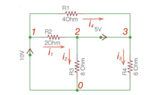
Consider the following figure :
There are two possibilities that exist:
Applying Kirchhoff’s Law we achieve the following equations:
i 1 + i4 = i2 + i3
-v2 +5+v3 =0
v 1 =10
By Ohm’s Law
These equations will help determine node voltages.
Summary of Supernode Analysis (Step by Step)
At last, solve the system of equations for the Nodal voltages such as V1, V2, and V3 etc. there will be (N-1, where “N” = Number of Nodes) of them. If you find difficulties to solve the system of equations, refer to the above solved example.
7. Explain source transformation?
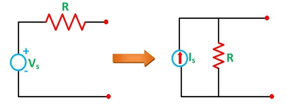
Source Transformation: Conversion of Voltage Source into Current Source
When the voltage source is connected with the resistance in series and it has to be converted into the current source than the resistance is connected in parallel with the current source as shown in the above figure.
Where Is = Vs /R
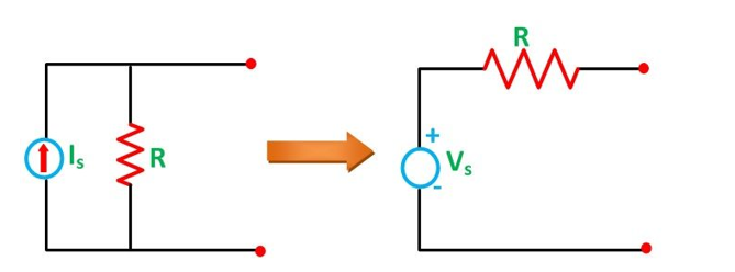
Conversion of Current Source into Voltage Source
In the above circuit diagram a current source which is connected in parallel with the resistance is transformed into a voltage source by placing the resistance in series with the voltage source.
Where, Vs = Is / R
8. Explain source shifting?
Source Shifting : We mean by either shifting current source or voltage source.
Shifting voltage source:
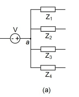
The figure shows node a at which the positive terminal of the voltage source V is connected to a couple of impedances Z1 to Z4. Here we can't transform the voltage source, V, as it has no impedance in series with it. However, we can push this voltage source through the node, a, towards the individual branches of the network. But while doing so, we have to take care that the current distribution through the circuit remains unaffected.
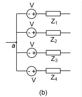
Figure b shows the resultant circuit obtained by the push through mechanism of the voltage source. At this instant, we observe that, after V-shift, the voltage source is made to appear at every branch of the electrical network in series with the impedances present in each of them.
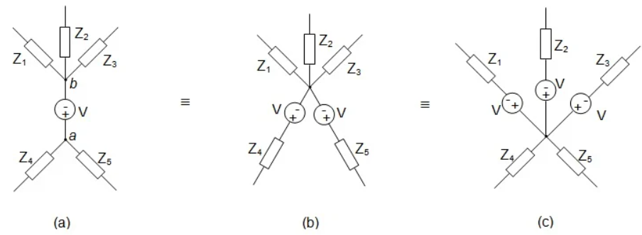
Consider the case where there are a couple of impedances joined at either ends of the voltage source. That is, Z1, Z2, and Z3 are connected to the negative terminal of the voltage source, V, while Z4 and Z5 are connected to its positive terminal.
The voltage source, V, in Figure a can either be (i) pushed through the node, a, towards the individual branches Z4 and Z5 or (ii) pulled through the node, b, towards the individual branches Z1, Z2, and Z3.
The networks resulting from such push-pull operation are shown by Figures b and c, respectively.
Shifting of current source:
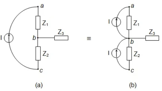
This concept can be better understood by considering an example as the one shown in Figure a. Here, there is a current source, I, connected between the nodes, a and c, such that current leaves node c and enters into node a.
This circuit can be redrawn as shown in Figure b wherein the identical current source is made to exit from node c, enter into node b, exit from node b, and enter into node a.
Here we should note that, even though the current is made to enter node b, it has no effect on the node. This is because an identical amount of current is made to exit from node b. This means that the circuits shown in Figures a and b are equivalent to each other, except for the fact that one may apply current-to-voltage source transformation readily for the circuit shown in Figure b.
9.Explain super position theorem?
Superposition theorem states that in any linear, active, bilateral network having more than one source, the response across any element is the sum of the responses obtained from each source considered separately and all other sources are replaced by their internal resistance. The superposition theorem is used to solve the network where two or more sources are present and connected.
If a number of voltage or current sources are acting in a linear network, the resulting current in any branch is the algebraic sum of all the currents that would be produced in it when each source acts alone while all the other independent sources are replaced by their internal resistances.
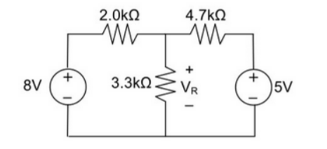
10.Using Superposition theorem determine the voltage drop and current across the resistor 3.3K as shown in figure below
Step 1:
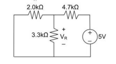
Remove 8V power supply from the original circuit such that the new circuit becomes as the following and measure the voltage across resistor.
Here 3.3 K and 2K are in parallel therefore the resultant resistance will be 1.245K
Using voltage divider rule across 1.245K will be
V1 =[1.245/(1.245+4.7)] * 5 = 1.047V
Step 2:
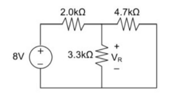
Remove the 5V power supply from the original circuit such that the new circuit becomes the following and then measure the voltage across resistor.
Here 3.3K and 4.7K are in parallel therefore the resultant resistance will be 1.938K. Using voltage divider rule voltage across 1.938K will be
V2 =[1.938(1.938+2)] *8 = 3.9377V
Therefore, voltage drop across 3.3K resistor is V1+V2 = 1.047 + 3.9377 = 4.9847V
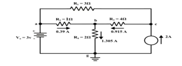
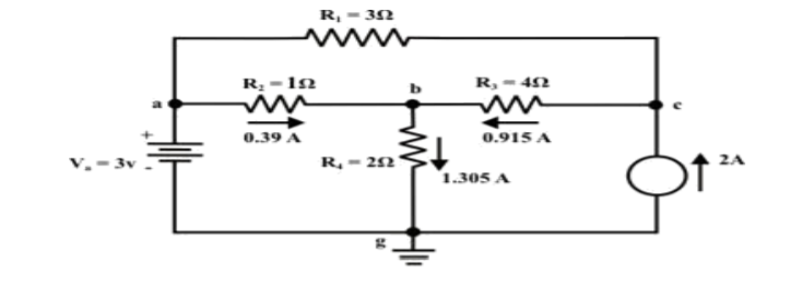
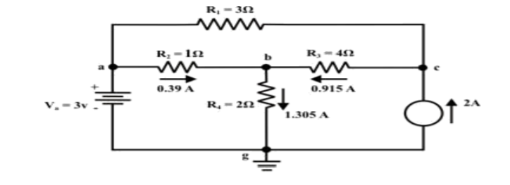
11.For the circuit as shown in figure find the current through RL = R2 = 1Ω resistor (Ia-b) branch using Thevenin’s theorem. Find the voltage across the current source.
Step 1: Disconnect the load resistance and reconnect the circuit.
Step 2: Apply any method to calculate Vth
At node C
2 + I1 + I2 =0
2 + (3 -Vc)/3 + (0-Vc/6) -- Vc = 6V
The currents I1 and I2 are computed by the following expressions:
I1 = Va -Vc/3 = 3-6/3 = -1A (I1 is flowing from c to a)
I2 = 0 – Vc/6 = -6/6 = -1A (I2 is flowing from c to a)
Step-3:
Redraw the circuit indicating the direction of currents in different branches. One can find the Thevenin’s voltage VTh using KVL around the closed path ‘gabg’
VTh = Vag − Vbg = 3 − 2 =1volt
Step 4:
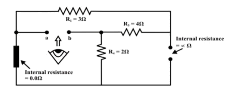
Replace all sources by their internal resistances. In this problem, voltage source has an internal resistance zero (0) (ideal voltage source) and it is short-circuited with a wire.
On the other hand, the current source has an infinite internal resistance (ideal current source) and it is open-circuited (just remove the current source).
Thevenin’s resistance RTh of the fixed part of the circuit can be computed by looking at the load terminals ‘a’- ‘b’
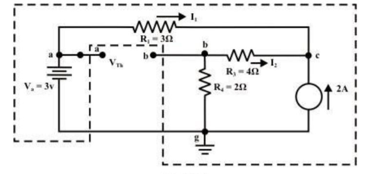
RTh = ( R1 + R3 ) & R4 = ( 3 + 4 )&2 = 1.555Ω
Step-5: Place RTh in series with VTh to form the Thevenin’s equivalent circuit. Reconnect the original load resistance RL = R2 = 1 Ω to the Thevenin’s equivalent circuit .
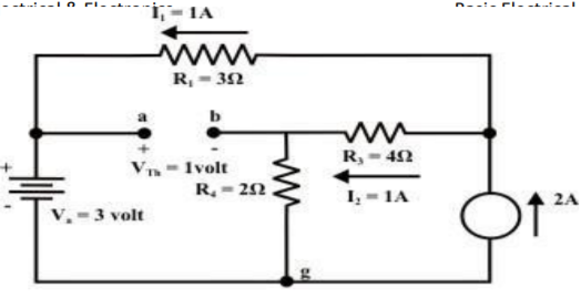
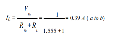
Step-6: The circuit is redrawn to indicate different branch currents. Referring to one can calculate the voltage Vbg and voltage across the current source (Vcg ) using the following equations.
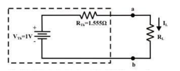
Vbg = Vag − Vab = 3 − 1 × 0.39 =2.61 volt.
Ibg = 2.61 2 = 1.305 A;
Icb = 1.305 − 0.39 = 0.915 A
Vcg = 4 × 0.915 + 2 ×1.305 =6.27 volt.
12. Explain maximum power transfer theorem?
Maximum power transfer theorem states that AC voltage source will deliver maximum power to the variable complex load only when the load impedance is equal to the complex conjugate of source impedance.
Proof:
Replace any two terminal linear network or circuit to the left side of variable load resistor having resistance of RL ohms with a Thevenin’s equivalent circuit. We know that Thevenin’s equivalent circuit resembles a practical voltage source.
The amount of power dissipated across the load resistor is
PL = I 2 R L ----------------------(1)
Substitute I = Vth / Rth + RL
PL = Vth / (Rth + RL ) 2 RL
PL = Vth 2 { RL / (RTH + RL) 2 ------------------------------(2)
Condition for Maximum Power Transfer
For maximum or minimum, first derivative will be zero. So, differentiate Equation 1 with respect to RL and make it equal to zero.
dPL / d RL = V Th 2 { (Rth + RL) 2 x 1 -RL x 2(Rth + RL) / (Rth + RL) 4 } =0
(Rth + RL) 2 – 2RL (Rth + RL) = 0
(Rth + RL) (Rth + RL – 2 RL) = 0
Rth - RL = 0
Rth = RL or RL = Rth
Therefore, the condition for maximum power dissipation across the load is RL=RTh. That means, if the value of load resistance is equal to the value of source resistance that is Thevenin’s resistance, then the power dissipated across the load will be of maximum value.
Substitute RL = Rth and PL = PL,max
PL,max = V th 2 { Rth / (Rth + Rth ) 2 }
= V th 2 ( Rth / 4 Rth 2 )
= V th 2 / 4 Rth
PL,max = V th 2 / 4 RL [RL = Rth]
Efficiency of Maximum power transfer
 = PL,max/ Ps
PL,max = maximum amount of power transferred to the load
Ps = amount of power generated by the source.
The amount of power generated by the source is
Ps = I2 Rth + I2 RL
Ps = 2 I2 Rth ; since RL = Rth
Substitute I = Vth / 2 Rth
Ps = 2(Vth / 2Rth) 2 Rth
Ps = 2(Vth / 4Rth) 2 Rth
Ps = Vth 2 / 2 Rth
Substituting with PL max and Ps
 = (Vth 2 / 4 Rth) / (Vth 2 / 2 Rth)
 max = ½
13. Find the maximum power that can be delivered to the load resistor RL of the circuit shown in the following figure.
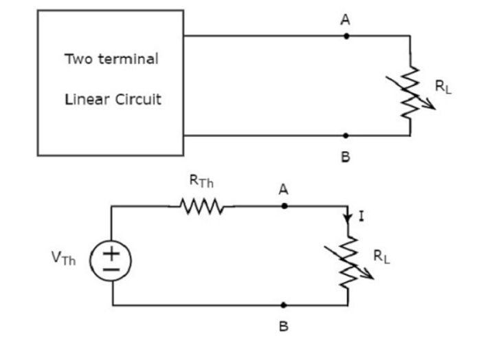
Step 1 – Using Thevenin’s circuit we get

Thevenin’s voltage Vth = 200/3 and Thevenin’s resistance Rth = 40/3
Step 2 – Replace the left side of terminals A & B of the given circuit with the above Thevenin’s equivalent circuit. The resultant circuit diagram will be

Step 3 − We can find the maximum power that will be delivered to the load resistor, RL by using the following formula.
P L,max = Vth 2 / 4 Rth
Substitute VTh=200/3 and RTh=40/3Ω
P L,max = (200/3) 2 / 4 (40/3)
Therefore, the maximum power that will be delivered to the load resistor RL of the given circuit is 250/3 .