Unit III
Two Port Network Parameters and Functions
Z parameters are also known as impedance parameters.
When we use Z parameter for analyzing two part network, the voltages are represented as the function of currents. So,
V1 = f1(I1,I2) and V2 = f2(I1,I2)
The Z parameters are,
Z11 = Input impedance keeping output open = V1/I1 | I2 =0
Z22 = Output impedance keeping input open = V2 / I2 | I1 =0
Z12 = Reverse transfer impedance keeping input open = V1 / I2 | I1 =0
Z21 = Forward transfer impedance keeping output open = V2/I1 | I2 =0
The voltages are represented as
V1 = Z11 I1 + Z12 I2 and V2 = Z21 I1 + Z22 I2 

2. Explain the terminal characteristics of h parameters?
h Parameter
h parameters also known as hybrid parameters.
V1 = f1 (I1,V2) - V1 = h11 I1 + h12 V2
I2 = f2 (I1,V2 ) -- I2 = h21 I1 + h22 V2 
In hybrid parameter circuit, voltage gain, current gain, impedance and admittance are used to determines relation between current and voltage of two port network.
Hence,
h11 = input impedance keeping the output terminals short circuited V1/I1 | V2 =0
h21 = Forward current gain keeping output terminals short circuited = I2/I1 | V2 =0
h12 = Reverse voltage gain keeping input open = V1/V2 | I1=0
h22 = Output admittance keeping input open = I2 /V2 | I1=0
3. Explain the characteristics of ABCD parameter?
ABCD Parameter
These are also called transmission parameters. Here, voltage and current and of input part are expressed in term of output part.
Here,
V1 = AV2 -BI2 and I1 = CV2 – DI2
In matrix form it can be written as,

A = V1 / V2 | I2 =0 Reverse voltage gain keeping output open circuited
B = V1 / V2 |V2 =0 Reverse transfer admittance keeping output short circuited
C = I1/ V2 | I2 =0 Reverse transfer admittance keeping output open circuited.
D = I1/ I2 | V2 =0 Reverse current gain keeping output short circuited.
V1 = Z11 I1 + Z12 I2 and V2 = Z21 I1 + Z22 I2


4. Explain the characteristics of Y parameter?
Y Parameters
Y parameter is dual of Z parameter.
Y11 = I1/V1 | V2 =0 = Input admittance keeping output short circuited.
Y22 = I2/V2 | V1 =0 Output admittance keeping input short circuited
Y12 = I1 / V2 | V1 =0 = Output admittance keeping input short circuited
Y21 = I2 / V1 | V2 =0 = Forward transfer admittance keeping input short circuited.
In the two part network represented by admittance, the current and voltage related by the following equations,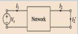
5. Explain symmetry and reciprocity condition?
For a network to be symmetrical the voltage to current ratio at one port should be the same as the voltage to current ratio at the other port short circuited.
Condition for symmetry:
V1 = Z11 I1 + Z12 I2
V2 = Z21 I1 + Z22 I2
When the output port is open circuited ie I2 =0
From the Z parameter equation
Vs = Z11 I1
Vs /I1 = Z11
When the input port is open circuited I1 =0
From the Z-parameter equation
Vs = Z22 I2
Vs / I2 = Z22
Hence for the network to be symmetrical
Vs / I1 = Vs / I2
Reciprocity:
A network is said to be reciprocal if the ratio of excitation at one port to response at other port is same if excitation and responses are interchanged.
Condition for reciprocity
V1 = Vs
V2 =0
I2 = - I2 ‘
Vs = Z11 I1 – Z12 I2’
0 = Z21 I1 – Z22 I2 ‘
I1 = Z22/ Z21 I2’
Vs = Z11 . Z22/ Z21 . I2 ‘ – Z12 I2 ‘
Vs / I2’ = Z11 Z22 – Z12 Z21 / Z21
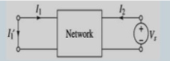
V2 = Vs
V1 =0
I1 = I1 ‘
0 = -Z11 I1 ‘ + Z12 I2
Vs = -Z21 I1’ + Z22 I2
I2 = Z11/ Z12 . I1’
Vs = -Z21 I1’ + Z22 . Z11/ Z12 . I1’
Vs / I1’ = Z11 Z22 – Z12 Z21 / Z12
Hence for the network to be reciprocal
Vs/I1’ = Vs / I2’
Z12 = Z21
6. Explain the application of Laplace transform?
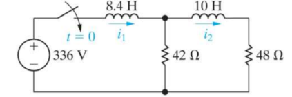
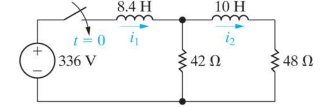
For the given circuit find i1(t) and i2(t)
-336/s + (42 + 8.4s) I1 – 42 I2 =0
(10s + 90) I2 – 42 I1 =0
I1 = 10s +90/42 I2
Substituting
-336/s + [ (42 +8.4 s) (10s+90) / 42 -42] I2 =0
I2(s) = 336(42)/ s[(42+8.4s)(10s+90)] - 42 2 = 168/ s3 + 14s2 + 24s
I1(s) = 10s+90/42 [ 168/ s3 + 14s2 + 24s] =40s+360/s3 + 14s2 + 24s
7. Explain the network function of one port network?
A port is a pair of terminals in a network at which electric energy or a signal may enter or leave the network. A network that has only one pair a terminal is called a one-port network. In one-port network, the current that enters one terminal must exit the network through the other terminal. Thus, in Figure, i in = i out

Figure One-port network
Figures (a) and (b) show two examples of practical one-port networks.
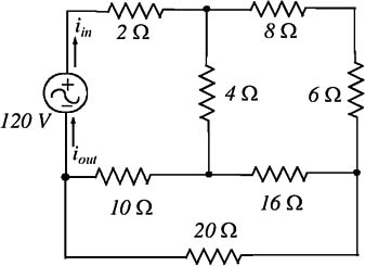
Figure (a): An example of an one-port network

Figure (b) Another example of an one-port network
8. Explain network function of two port network?
A two-port network has two pairs of terminals, that is, four terminals as shown in Figure where i 1 = i 3 and i 2 = i 4

Figure: Two-port network
9. Explain poles and zeros of network function?
The transfer function provides a basis for determining important system response characteristics without solving the complete differential equation.
As defined, the transfer function is a rational function in the complex variable
s = σ + jω,

It is often convenient to factor the polynomials in the numerator and denominator, and to write the transfer function in terms of those factors
Where the numerator and denominator polynomials, N(s) and D(s), have real coefficients defined by the system’s differential equation and K = bm/an. As written in Eq. (2) the zi’s are the roots of the equation
N(s) =0 and are defined to be the system zeros,
and the pi’s are the roots of the equation
D(s) = 0,
and are defined to be the system poles.
In Eq. (2) the factors in the numerator and denominator are written so that when
s = zi the numerator N(s) = 0 and the transfer function vanishes, that is
lim s->z1 H(s) =0
and similarly when s = pi the denominator polynomial D(s) = 0 and the value of the transfer function becomes unbounded,
lim s->p1 H(s) -> ∞
All of the coefficients of polynomials N(s) and D(s) are real, therefore the poles and zeros must be either purely real, or appear in complex conjugate pairs.
In general for the poles, either pi = σi , or else pi , pi+1 = σi+jωi . The existence of a single complex pole without a corresponding conjugate pole would generate complex coefficients in the polynomial D(s). Similarly, the system zeros are either real or appear in complex conjugate pairs.

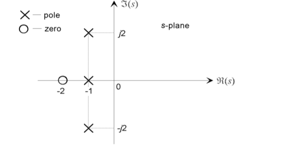
The Pole-Zero Plot A system is characterized by its poles and zeros in the sense that they allow reconstruction of the input/output differential equation.
In general, the poles and zeros of a transfer function may be complex, and the system dynamics may be represented graphically by plotting their locations on the complex s-plane, whose axes represent the real and imaginary parts of the complex variable s. Such plots are known as pole-zero plots. It is usual to mark a zero location by a circle (◦) and a pole location a cross (×). The location of the poles and zeros provide qualitative insights into the response characteristics of a system.
10. Explain system stability?
System Stability: The stability of a linear system may be determined directly from its transfer function. An nth order linear system is asymptotically stable only if all of the components in the homogeneous response from a finite set of initial conditions decay to zero as time increases, or

Where the pi are the system poles. In a stable system all components of the homogeneous response must decay to zero as time increases.
If any pole has a positive real part there is a component in the output that increases without bound, causing the system to be unstable.
In order for a linear system to be stable, all of its poles must have negative real parts that are they must all lie within the left-half of the s-plane.
An ―unstable‖ pole, lying in the right half of the s-plane, generates a component in the system homogeneous response that increases without bound from any finite initial conditions.
A system having one or more poles lying on the imaginary axis of the s-plane has non-decaying oscillatory components in its homogeneous response, and is defined to be marginally stable.