Unit 4
DC Machines
Construction of DC Machine
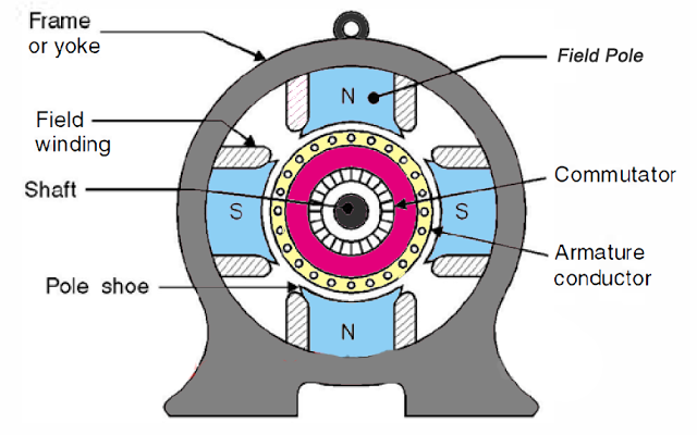
The construction of DC machine can be done using some of the essential parts like Yoke, Pole core & pole shoes, Pole coil & field coil, Armature core, Armature winding otherwise conductor, commutator, brushes & bearings. Some of the parts of the DC machine.
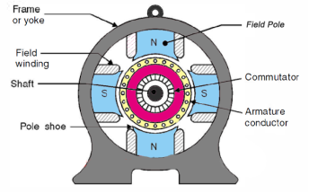
Construction of DC Machine
Yoke
Another name of a yoke is the frame. The main function of the yoke in the machine is to offer mechanical support intended for poles and protects the entire machine from the moisture, dust, etc. The materials used in the yoke are designed with cast iron, cast steel otherwise rolled steel.
Pole and Pole Core
The pole of the DC machine is an electromagnet and the field winding is winding among pole. Whenever field winding is energized then the pole gives magnetic flux. The materials used for this are cast steel, cast iron otherwise pole core. It can be built with the annealed steel laminations for reducing the power drop because of the eddy currents.
Pole Shoe
Pole shoe in DC machine is an extensive part as well as enlarge the region of the pole. Because of this region, flux can be spread out within the air-gap as well as extra flux can be passed through the air space toward armature. The materials used to build pole shoe is cast iron otherwise cast steed, and also used annealed steel lamination to reduce the loss of power because of eddy currents.
Field Windings
In this, the windings are wounded in the region of pole core & named as field coil. Whenever current is supplied through field winding then it electromagnetics the poles which generate required flux. The material used for field windings is copper.
Armature Core
Armature core includes the huge number of slots within its edge. Armature conductor is located in these slots. It provides the low-reluctance path toward the flux generated with field winding. The materials used in this core are permeability low-reluctance materials like iron otherwise cast. The lamination is used to decrease the loss because of the eddy current.
Armature Winding
The armature winding can be formed by interconnecting the armature conductor. Whenever an armature winding is turned with the help of prime mover then the voltage, as well as magnetic flux, gets induced within it. This winding is allied to an exterior circuit. The materials used for this winding are conducting material like copper.
Commutator
The main function of the commutator in the DC machine is to collect the current from the armature conductor as well as supplies the current to the load using brushes. And also provides uni-directional torque for DC-motor. The commutator can be built with a huge number of segments in the edge form of hard drawn copper. The Segments in the commutator are protected from thin mica layer.
Brushes
Brushes in the DC machine gather the current from commutator and supplies it to exterior load. Brushes wear with time to inspect frequently. The materials used in brushes are graphite otherwise carbon which is in rectangular form.
Working:
The DC motor is the device which converts the direct current into the mechanical work. It works on the principle of Lorentz Law, which states that “the current-carrying conductor placed in a magnetic and electric field experience a force”. The experienced force is called the Lorentz force. The Fleming left-hand rule gives the direction of the force.
The formula calculates the magnitude of the force,
F = B I l newton
The armature and stator are the two main parts of the DC motor. The armature is the rotating part, and the stator is their stationary part. The armature coil is connected to the DC supply.
The armature coil consists the commutators and brushes. The commutators convert the AC induced in the armature into DC and the brushes transfer the current from rotating part of the motor to the stationary external load. The armature is placed between the north and south pole of the permanent or electromagnet.
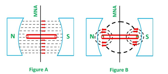
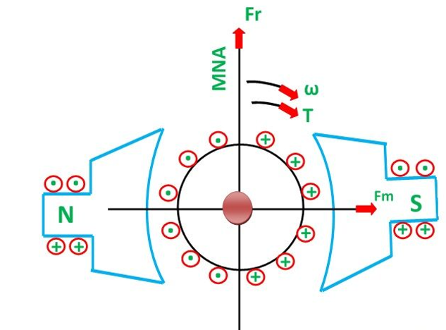
Consider that the armature has only one coil which is placed between the magnetic field shown below in the figure A. When the DC supply is given to the armature coil the current starts flowing through it. This current develops its own field around the coil.
Figure B shows the field induces around the coil:
By the interaction of the fields (produced by the coil and the magnet), the resultant field develops across the conductor. The resultant field tends to regain its original position, i.e. in the axis of the main field. The field exerts the force at the ends of the conductor, and thus the coil starts rotating.
Let the field produced by the main field be Fm, and this field rotates in the clockwise direction. When the current flows in the coil, they produce their own magnetic field say, Fr. The field Fr tries to come in the direction of the main field. Thereby, the torque act on the armature coil.
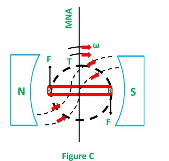
The actual DC motor consists of a large number of armature coils. The speed of the motor is directly proportional to the number of coils used in the motor. These coils are kept under the impact of the magnetic field.
The one end of the conductors is kept under the influence of the north pole, and the other end is kept under the influence of the south pole. The current enters into the armature coil through the north pole and move outwards through the south pole.
When the coil moves from one brush to another, at the same time the polarity of the coil also changes. Thus, the direction of the force or torque acting on the coil remains the same.
The torque induces in the coil become zero when the armature coil is perpendicular to the main field. The zero torque means the motor stops rotating. For solving this problem, the number of armature coil is used in the rotor. So, if one of their coils is perpendicular to the field, then the other coils induce the torque. And the rotor moves continuously.
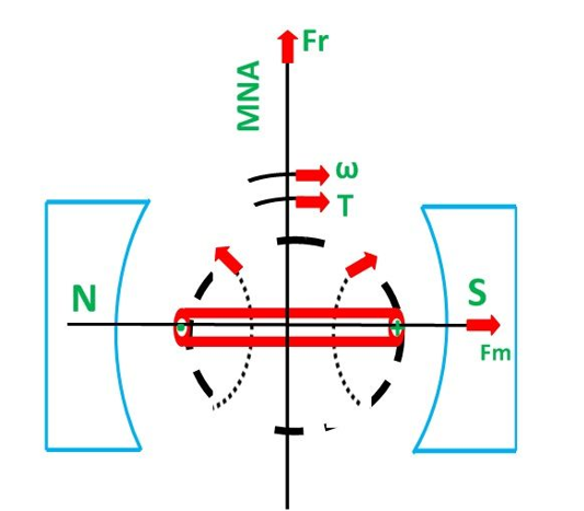
Also, for obtaining the continuous torque, the arrangement is kept in such a way that whenever the coils cut the magnetic neutral axis of the magnet the direction of current in the coils become reversed. This can be done with the help of the commutator.
2. Explain the EMF equation?
The DC machine e.m.f can be defined as when the armature in the dc machine rotates, the voltage can be generated within the coils.
In a generator, the e.m.f of rotation can be called the generated emf, and Er=Eg.
In the motor, the emf of rotation can be called as counter or back emf, and Er=Eb.
Let Φ is the useful flux for every pole within Weber’s
P is the total number of poles
z is the total number of conductors within the armature
n is the rotation speed for an armature in the revolution for each second
A is the no. of parallel lane throughout the armature among the opposite polarity brushes.
Z/A is the no. of armature conductor within series for each parallel lane
As the flux for each pole is ‘Φ’, every conductor slashes a flux ‘PΦ’ within a single revolution.
The voltage produced for each conductor = flux slash for each revolution in WB / Time taken for a single revolution within seconds
As ‘n’ revolutions are completed within a single second and 1 revolution will be completed within a 1/n second. Thus, the time for a single armature revolution is a 1/n sec.
The standard value of produced voltage for each conductor
p Φ/1/n = np Φ volts
The voltage produced (E) can be decided with the no.of armature conductors within series I any single lane among the brushes thus, the whole voltage produced
E = standard voltage for each conductor x no. of conductors within series for each lane
E = n.P.Φ x Z/A
The above equation is the e.m.f. the equation of the DC machine.
3. Explain the types of DC generator?
There are three methods of excitation, and thus three main types of DC generators:
Self-excited DC generators are classified depending on the position of their field coils. The three types of self-excited DC generators are:
A portable generator is an example of a practical application that utilises such technologies.
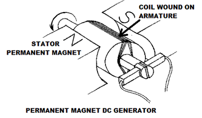
Permanent Magnet DC Generator
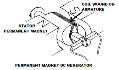
When the flux in the magnetic circuit is created through the use of permanent magnets, then it is known as a Permanent magnet DC generator.
It consists of an armature and one or several permanent magnets situated around the armature. This type of DC generator generates does not generate much power.
As such they are rarely found in industrial applications. They are normally used in small applications – like dynamos in motorcycles.
Separately Excited DC Generator
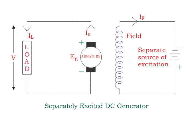
These are the generators whose field magnets are energized by some external DC source, such as a battery.
A circuit diagram of separately excited DC generator is shown in the figure below. The symbols below are:
Voltage drop in the armature = Ia × Ra (R/sub>a is the armature resistance )
Let,
Ia = IL = I
Then,
Voltage across the load V = I Ra
Power generated is equal to
Pg = Eg x I
And power delivered to the external load is equal to
PL = V x I
Self -Excited DC Generators
Self-excited DC generators are generators whose field magnets are energized by the current supplied by themselves.
In this type of machines, field coils are internally connected with the armature.
Due to residual magnetism, some flux is always present in the poles.
When the armature is rotated, some EMF is induced. Hence some induced current is produced. This small current flows through the field coil as well as the load and thereby strengthening the pole flux.
As the pole flux strengthened, it will produce more armature EMF, which cause the further increase of current through the field. This increased field current further raises armature EMF, and this cumulative phenomenon continues until the excitation reaches the rated value.
According to the position of the field coils, self-excited DC generators may be classified as:
Series Wound Generator
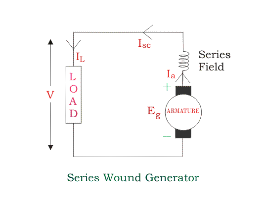
In these types of generators, the field windings are connected in series with armature conductors, as shown in the figure below.
Whole current flows through the field coils as well as the load. As series field winding carries full load current it is designed with relatively few turns of thick wire. The electrical resistance of series field winding is therefore very low (nearly 0.5Ω ).
Here:
Then,
Ia = Isc = IL = I
Voltage across the load is equal to,
V = Eg – I ( Ia x Ra )
Power generated is equal to,
Pg = Eg x I
Power delivered to the load is equal to,
PL = V x I
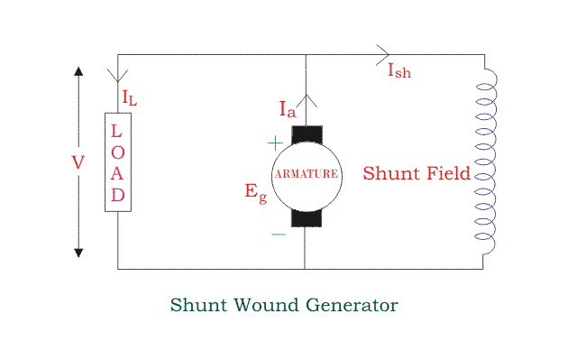
Shunt Wound DC Generators
In these type of DC generators, the field windings are connected in parallel with armature conductors, as shown in the figure below. In shunt wound generators the voltage in the field winding is same as the voltage across the terminal.
Here:
Here armature current Ia is dividing in two parts – one is shunt field current Ish, and another is load current IL.
So,
Ia = Ish + IL
The effective power across the load will be maximum when IL will be maximum. So, it is required to keep shunt field current as small as possible.
For this purpose the resistance of the shunt field winding generally kept high (100 Ω) and large no of turns are used for the desired EMF.
Shunt field current is equal to,
Ish = V/Rsh
Voltage across the load is equal to,
V= Eg – Ia Ra
Power generated is equal to,
Pg = Eg x Ia
Power delivered to the load is equal to,
PL = V x IL
Compound Wound DC Generator
In series wound generators, the output voltage is directly proportional with load current .In shunt wound generators, the output voltage is inversely proportional with load current.
A combination of these two types of generators can overcome the disadvantages of both. This combination of windings is called compound wound DC generator.
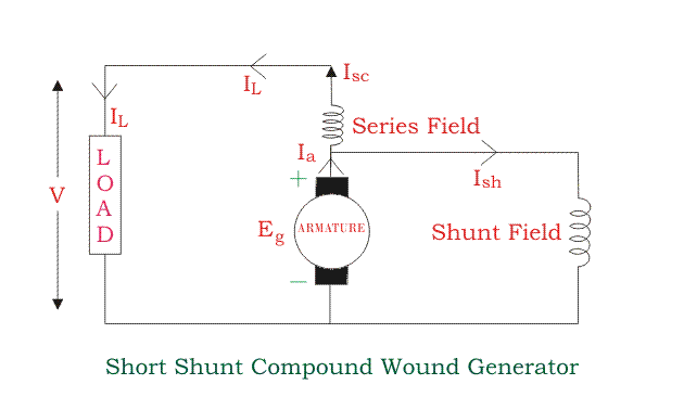
Compound wound generators have both series field winding and shunt field winding. One winding is placed in series with the armature, and the other is placed in parallel with the armature. This type of DC generators may be of two types- short shunt compound-wound generator and long shunt compound-wound generator.
Short Shunt Compound Wound DC GeneratorShort Shunt Compound Wound DC Generators are generators where only the shunt field winding is in parallel with the armature winding as shown in the figure below.
Series field current is equal to,
Isc = IL
Shunt field current is equal to,
Ish = (V + Isc Rsc) / Rsh
Armature current is equal to,
Ia = Ish + IL
Voltage across the load is equal to,
V = Eg – Ia Ra – Isc Rsc
Power generated is equal to,
Pg = Eg x Ia
Power delivered to the load is equal to,
PL = V x IL
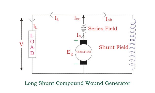
Long Shunt Compound Wound DC GeneratorLong Shunt Compound Wound DC Generator are generators where the shunt field winding is in parallel with both series field and armature winding , as shown in the figure below.
Shunt field current is equal to,
Ish = V/Rsh
Armature current, Ia = series field current,
Isc = IL + Ish
Voltage across the load is equal to,
V = Eg – Ia Ra – Isc Rsc = Eg – Ia( Ra + Rsc)
Power generated is equal to,
Pg = Eg x Ia
Power delivered to the load is equal to,
PL = V x IL
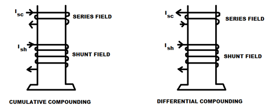
In a compound wound generator, the shunt field is stronger than the series field. When the series field assists the shunt field, generator is said to be commutatively compound wound.
On the other hand, if the series field opposes the shunt field, the generator is said to be differentially compound wound.
4. Explain the voltage equation of DC generator?
As the armature rotates, a voltage is generated in its coils. In the case of a generator, the emf of rotation is called the Generated emf or Armature emf and is denoted as Er = Eg.
Let,
In one revolution of the armature, the flux cut by one conductor is given as:
Flux cut by one conductor = P ɸ wb ------------------------(1)
Time taken to complete one revolution is given as:
t = 60/ N seconds ------------------------------------------(2)
Therefore, the average induced e.m.f in one conductor will be:
e=Pɸ/t ----------------------------------------------------------(3)
Putting the value of (t) from Equation (2) in the equation (3) we will get
e = Pɸ/ 60/N = PɸN/60 volts -----------------------------------------(4)
The number of conductors connected in series in each parallel path = Z/A.
Therefore, the average induced e.m.f across each parallel path or the armature terminals is given by the equation shown below:
E = PɸN/60 x Z/A = PɸNZ/60A volts or
E = PZɸN/A -----------------------------------------------------------------(5)
Where n is the speed in revolution per second (r.p.s) and given as:
n = N/60
For a given machine, the number of poles and the number of conductors per parallel path (Z/A) are constant. Hence, equation (5) can be written as:
E = K ɸ n
Where K is a constant and given as:
K = PZ/A
Therefore, the average induced emf equation can also be written as:
E α ɸ n or
E = K1 ɸ N
Where K1 is another constant and hence induced emf equation can be written as:
E α ɸ N or
E α ɸ w
Where ω is the angular velocity in radians/second is represented as:
w = 2πN/60
Thus, the induced emf is directly proportional to the speed and flux per pole. The polarity of induced emf depends upon the direction of the magnetic field and the direction of rotation. If either of the two is reversed the polarity changes, but if two are reversed the polarity remains unchanged.
This induced emf is a fundamental phenomenon for all the DC Machines whether they are working as a generator or motor.
If the DC Machine is working as a Generator, the induced emf is given by the equation shown below:
Eg = PZɸN/60 A volts
Where Eg is the Generated Emf
5. Explain the working principle of DC generator?
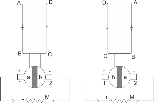
In the first half of the revolution current always flows along ABLMCD, i.e., brush no 1 in contact with segment a. In the next half revolution, in the figure, the direction of the induced current in the coil is reversed.
But at the same time the position of the segments a and b are also reversed which results that brush no 1 comes in touch with the segment b. Hence, the current in the load resistance again flows from L to M. The waveform of the current through the load circuit is as shown in the figure. This current is unidirectional.
The above content is the basic working principle of DC generator, explained by single loop generator model. The positions of the brushes of DC generator are so that the change over of the segments a and b from one brush to other takes place when the plane of rotating coil is at a right angle to the plane of the lines of force. It is to become in that position, the induced EMF in the coil is zero.
5.Explain torque equation?
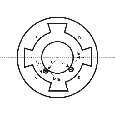
In the diagram Area per pole Ar = 2 π r L /P
B = ɸ/Ar
B = P ɸ / 2 π r L
Current/conductor Ic = Ia A
Therefore, force per conductor = fc = BLIa/A
Now torque Tc = fc. r = BLIa.r/A
Tc = ɸ P Ia / 2 π A
Hence, the total torque developed of a DC machine is,
Tg = PZɸ Ia / 2π A
This torque equation of DC motor can be further simplified as:
Tg = ka ɸ Ia
Where ka = P.Z / 2 π A
Which is constant for a particular machine and therefore the torque of DC motor varies with only flux φ and armature current Ia.
6. Explain the speed equation of DC motor?
The back emf Eb of a DC motor is nothing but the induced emf in armature conductors due to rotation of the armature in magnetic field. Thus, the magnitude of Eb can be given by EMF equation of DC generator.
Eb = PØNZ/60A
(where, P = no. of poles, Ø = flux/pole, N = speed in rpm, Z = no. of armature conductors , A = parallel paths)
Eb can also be given as,
Eb = V- IaRa
thus, from the above equations
N = Eb 60 A / P ɸ Z
but, for a DC motor A, P and Z are constants
Therefore, N ∝ K Eb / ɸ (where, K=constant)
This shows the speed of a dc motor is directly proportional to the back emf and inversely proportional to the flux per pole.
7. Explain basic characteristics?
Characteristic is the graph between the two dependent quantities. It shows the steady-state characteristic of DC generators. The characteristic of the DC generators explains the relations between the loads, excitation and terminals voltage through the graph. Following are the three important characteristics of a DC Generator.
Magnetization Characteristic
This characteristic gives the variation of generating voltage or no-load voltage with field current at a constant speed. It is also called no-load or open circuit characteristic.
Internal Characteristic
Internal characteristic of DC Generator plots the curve between the generated voltage and load current.
External Characteristic (Load Characteristics)
External or load characteristics give the relation between the terminal voltage and load current at a constant speed.
8. Explain the different methods of speed control?
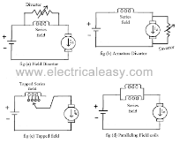
Armature diverter: Diverter is connected across the armature as shown in fig (b).For a given constant load torque, if armature current is reduced then the flux must increase, as Ta ∝ ØIa. This will result in an increase in current taken from the supply and hence flux Ø will increase and subsequently speed of the motor will decrease.
Tapped field control: As shown in fig (c) field coil is tapped dividing number of turns. Thus, we can select different value of Ø by selecting different number of turns.
Paralleling field coils: In this method, several speeds can be obtained by regrouping coils as shown in fig (d).
2. Variable Resistance in Series With Armature
By introducing resistance in series with the armature, voltage across the armature can be reduced. And, hence, speed reduces in proportion with it.
3. Series-Parallel Control
This system is widely used in electric traction, where two or more mechanically coupled series motors are employed. For low speeds, the motors are connected in series, and for higher speeds, the motors are connected in parallel.
When in series, the motors have the same current passing through them, although voltage across each motor is divided. When in parallel, the voltage across each motor is same although the current gets divided.
9. Explain power flow diagram of DC motor?
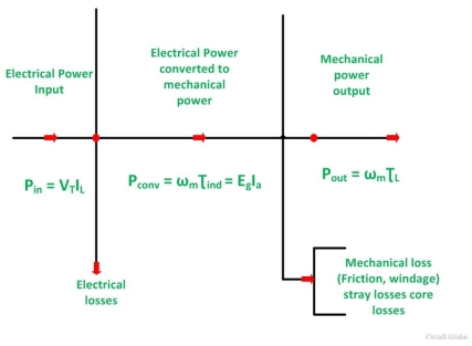
The power flow diagram of DC Motor is shown below:
Power Flow Diagram of DC Motor
From the power flow diagram of DC Motor, it’s clear that the input which is given to the motor is in the electrical form which is converted into mechanical power in the second stage. The output is in the form of mechanical power.
In a DC motor, the input electrical power Pin is given by the equation shown below:
Pin = VT IL ---------------------------(1)
Pconv = Pi – copper losses -------------------------(2)
Power output is given by the equation shown below.
Pout = wm τL ----------------------------------------------------------------------------(3)
Also,
Pout = Pconv – core losses – mechanical losses – stray losses -------------------(9)
Where,
ƮL is the load torque in Newton-meter
Thus, the power flow diagram gives an overview, that how one form of energy is converted into another form.
10. Explain the need of starter?
Starters are used to protect DC motors from damage that can be caused by high current and torque during start up. They do this by providing external resistance to the motor, which is connected in series to the motor’s armature winding and restricts the current to an acceptable level.
The reason DC motors experience high start-up current, we need to examine the voltage equation of a DC motor:
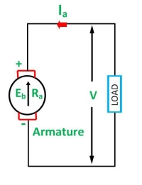
We know that
E = Eb + Ia . Ra
Where:
E = supply voltage
Eb = back EMF
Ia = armature current
Ra = armature resistance
Back EMF is directly proportional to the motor’s speed, so at start-up, when motor speed is zero, back EMF is also zero. Therefore, removing the Eb term and rearranging the voltage equation, we can see that, at start-up, armature current is inversely proportional to armature resistance.
Ia = E / Ra
For the best motor performance, armature resistance in DC motors is kept very low (typically less than 1 ohm).
Not only can the high start-up current result in potential motor circuit damage, it can also produce dangerously high torque, which can cause the rotor to literally break apart.
From the DC motor torque , we can see that torque is directly proportional to current:
T = ka . ɸ. Ia
Where:
T = torque
ka = torque constant
φ = motor flux
To combat these problems, a motor starter adds external resistance (Rs) to the armature winding, which reduces the armature current:
Ia = E/ Ra + Rs
But this resistance doesn’t need to be present through the motor’s full operating speed range.
As motor speed increases, back EMF develops, which counters the supply voltage and also has the effect of reducing armature current:
Ia = E.Eb / Ra + Rs
As the back EMF reaches its maximum, the starter progressively decreases the external resistance, Rs, to zero.
11. Explain three- point starter?
Three- point starter DC shunt motor
A 3- point starter is a device that helps in the starting and running of a DC shunt motor or compound wound DC motor.
A starter is a variable resistance, integrated into the number of sections as shown in the figure.
The contact points of these sections are called studs and are shown separately as OFF, 1, 2, 3, 4, 5, RUN.
There are three main points, referred to as
The construction of 3 point starter reveals that the point ‘L’ is connected to an electromagnet called overload release (OLR) as shown in the figure.
The other end of OLR is connected to the lower end of conducting lever of starter handle where spring is also attached with it, and the starter handle also contains a soft iron piece housed on it.
This handle is free to move to the other side RUN against the force of the spring. This spring brings back the handle to its original OFF position under the influence of its own force.
Another parallel path is derived from the stud ‘1’, given to another electromagnet called No Volt Coil (NVC) which is further connected to terminal ‘F.’ The starting resistance at starting is entirely in series with the armature. The OLR and NVC act as the two protecting devices of the starter.
Working of Three Point Starter
The working of the 3 point starter. To start with the handle is in the OFF position when the supply to the DC motor is switched on. Then handle is slowly moved against the spring force to contact stud No. 1.
At this point, field winding of the shunt or the compound motor gets supply through the parallel path provided to starting the resistance, through No Voltage Coil.
While entire starting resistance comes in series with the armature. The high starting armature current thus gets limited as the current equation at this stage becomes:
12. Explain four point starter?
Four -point starter:
A 4 -point starter protects the armature of a DC shunt motor or compound wound DC motor against the initially high starting current of the DC motor.
A 4- point starter as the name suggests has 4 main operational points, namely
A 4th point N (Connected to the No Voltage Coil NVC)
The difference in case of a 4 point starter is that the No Voltage Coil is connected independently across the supply through the fourth terminal called ‘N’ in addition to the ‘L’, ‘F’ and ‘A’.
As a direct consequence of that, any change in the field supply current does not bring about any difference in the performance of the NVC. Thus it must be ensured that no voltage coil always produce a force which is strong enough to hold the handle in its ‘RUN’ position, against the force of the spring, under all the operational conditions.
Such a current is adjusted through No Voltage Coil with the help of fixed resistance R connected in series with the NVC using fourth point ‘N’ as shown in the figure above.
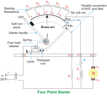 4 Point Starter Diagram
The 4 point and 3 point starters are similar in all other ways like possessing is a variable resistance, integrated into number of sections as shown in the figure above.
The contact points of these sections are called studs and are shown separately as OFF, 1, 2, 3, 4, 5, RUN, over which the handle is free to be maneuvered manually to regulate the starting current with gathering speed.
Considering that supply is given and the handle is taken stud No.1, then the circuit is complete and the line current that starts flowing through the starter.
In this situation the current will be divided into 3 parts, flowing through 3 different points.
So, the point to be noted here is that with this particular arrangement any change in the shunt field circuit does not bring about any change in the no voltage coil as the two circuits are independent of each other.
This essentially means that the electromagnet pull subjected upon the soft iron bar of the handle by the no voltage coil at all points of time should be high enough to keep the handle at its RUN position, or rather prevent the spring force from restoring the handle at its original OFF position, irrespective of how the field rheostat is adjusted.
13. Explain the application of DC motors?
Applications of DC motors
The main applications of the three types of direct current motors are given below.
Series Motors
The series DC motors are used where high starting torque is required and variations in speed are possible. For example – the series motors are used in the traction system, cranes, air compressors, Vaccum Cleaner, Sewing machine, etc.
Shunt Motors
The shunt motors are used where constant speed is required and starting conditions are not severe. The various applications of DC shunt motor are in Lathe Machines, Centrifugal Pumps, Fans, Blowers, Conveyors, Lifts, Weaving Machine, Spinning machines, etc.
Compound Motors
The compound motors are used where higher starting torque and fairly constant speed is required. The examples of usage of compound motors are in Presses, Shears, Conveyors, Elevators, Rolling Mills, Heavy Planners, etc.
The small DC machines whose ratings are in fractional kilowatt are mainly used as control device such in techno generators for speed sensing and in servo motors for positioning and tracking.
14. Explain PMDC?
The permanent magnet dc motor can be defined as a motor which includes a permanent magnet pole is called Permanent Magnet DC Motor.
In this motor, the magnet can be used to make the flux working within the air gap in its place of the field winding.
The rotor structure is similar to the straight DC Motor. PMDC Motor’s rotor includes armature core, commutator, & armature winding.
Construction of PMDC Motor
The PMDC motor’s permanent magnets are maintained with a cylindrical-steel stator and these supplies like a return lane for the magnetic flux.
The rotor supplies like an armature, and it includes commutator segments, winding slots, & brushes like in conventional dc machines.
The permanent magnets used in this motor are classified into three namely Alnico magnets, Ceramic (ferrite) magnets, and Rare-earth magnets.
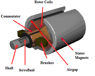 PMDC Motor Construction
Operation of PMDC Motor
In this motor, a permanent magnetic field can be generated with the permanent magnets which communicate by the perpendicular field stimulated by the flow of currents within the rotor windings; therefore, a mechanical torque can be created.
When the rotor rotates in response to the created torque, then the position among the stator as well as rotor fields can be reduced, and the torque would be reversed in a 90-degree rotation. To maintain the torque performing on the rotor, PMDC motors include a commutator, set to the rotor shaft.
The commutator activates the current supply toward the stator thus as to continue a steady angle = 90, among two fields. As the flow of current is frequently activated among windings like the rotor twists, then the current within every stator winding is truly exchanging at a frequency comparative to the no.of motor magnetic poles as well as the speed.
Advantages and Disadvantages of the PMDC Motor
The advantages and disadvantages of the PMDC motor include the following.
Applications of the PMDC Motor
The applications of the PMDC Motor include the following.
