Unit 5
Digital Representation of Analog Signals
- What is quantization of signals?
Quantization is representing the sampled values of the amplitude by a finite set of levels, which means converting a continuous-amplitude sample into a discrete-time signal
Both sampling and quantization result in the loss of information.
The quality of a Quantizer output depends upon the number of quantization levels used.
The discrete amplitudes of the quantized output are called as representation levels or reconstruction levels.
The spacing between the two adjacent representation levels is called a quantum or step-size.
2. Explain Quantization error?
Because of quantization inherent errors are introduced in the signal. This error is called quantization error. The quantization error is defined as
 = xq(nTs) – x(nTs) --------------------------------------------(1)
Let an input x(nTs) be of continuous amplitude in the range -xmax to + xmax .
Therefore the total amplitude range becomes,
Total amplitude range = xmax – (-max) --------------------------------------------(2)
= 2 xmax
If the amplitude range is divided into ‘q’ levels of the quantizer then the step size δ is given by
δ= xmax –(-xmax) /q = 2xmax/q -------------------------------------------------------(3)
If the signal x(t) is normalized to mimimum and maximum values equal to 1 then
Xmax = 11
-xmax = -1
Therefore step size will be
δ=2/q (for normalized signal)
3. Explain uniform and non-uniform quantization?
There are two types of uniform quantization
-Mid rise type
-Mid tread type
The following represent two types of uniform quantization
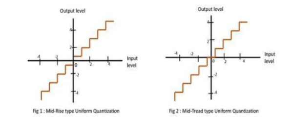
The mid-rise is so called because the origin lies in the middle of a raising part of the stair-case like graph. The quantization levels in this type are even in number.
The mid-tread is so called because the origin lies in the middle of a tread of the stair-case like graph. The quantization levels in this type are odd in number.
Both mid-rise and mid-tread type of uniform quantizer is symmetric about the origin.
Non-Uniform Quantization
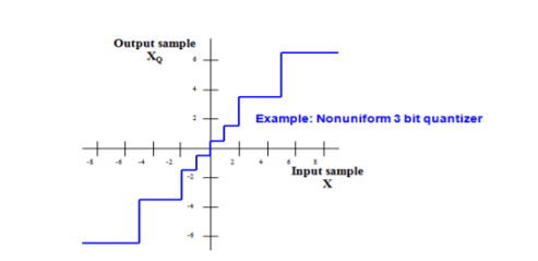
In non-uniform quantization the step size is not fixed. It varies according to certain law or as per input signal amplitude. The following fig shows the characteristics of Non-uniform quantizer.
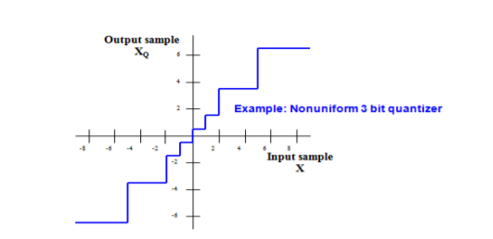
In this figure that step size is small at low input signal levls. Hence qunatization erroe is also small at these inputs. Therefore signal to quantization noise power ratio is improved at low signal levels. Stepsize is higher at high input levels. Hence signal to noise power ratio remains almost same throughout the dynamic range of quantizer.
4. Explain companding?
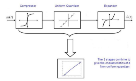
Non-uniform quantizers are difficult to make and expensive.
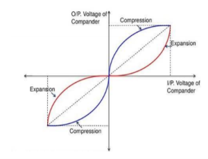
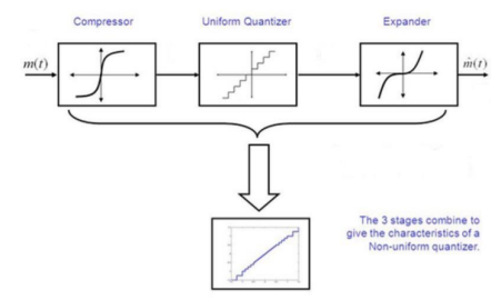
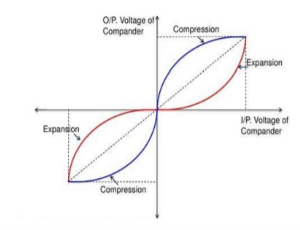
• An alternative is to first pass the speech signal through nonlinearity before quantizing with a uniform quantizer.
• The nonlinearity causes the signal amplitude to be compressed. – The input to the quantizer will have a more uniform distribution.
• At the receiver, the signal is expanded by an inverse to the nonlinearity.
• The process of compressing and expanding is called Companding
5. Explain μ-law and A-law companding?
Normally for speech and music signals a μ-law compression is used. This compression is defined by the following equation
Z(x) = (Sgn x) ln(1+μ|x|)/ ln(1+μ) |x|  1
1
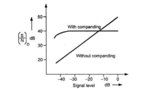
Below fig shows the variation of signal to noise ratio with respect to signal level without companding and with companding.
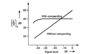
PCM performance with μ-law companding
A-law for companding
The A law provides piecewise compressor characteristic. It has linear segment for low level inputs and logarithmic segment for high level inputs. It is defined as
Z(x) = { A|x|/ 1 + ln A for 0
1 + ln(A|x|)/ 1 + ln A for 1/a  |x|
|x|  1
1
When A=1 we get uniform quantization. The practical value for A is 87.56. Both A-law and μ-law companding is used for PCM telephone systems.
6. Explain the generation and reconstruction of PCM system?
In Pulse Code Modulation, the message signal is represented by a sequence of coded pulses. This message signal is achieved by representing the signal in discrete form in both time and amplitude.
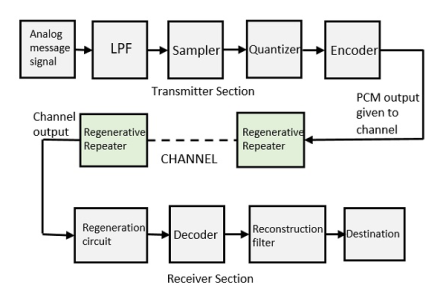
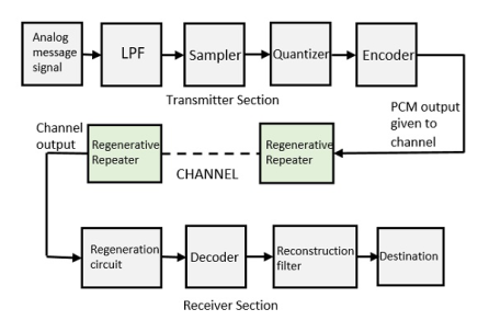
The transmitter section of a Pulse Code Modulator circuit consists of Sampling, Quantizing and Encoding, which are performed in the analog-to-digital converter section. The low pass filter prior to sampling prevents aliasing of the message signal.
The basic operations in the receiver section are regeneration of impaired signals, decoding, and reconstruction of the quantized pulse train. Figure shows the block diagram of PCM which represents the basic elements of both the transmitter and the receiver sections.
Low Pass Filter
This filter eliminates the high frequency components present in the input analog signal which is greater than the highest frequency of the message signal, to avoid aliasing of the message signal.
Sampler
This is the technique which helps to collect the sample data at instantaneous values of message signal to reconstruct the original signal. The sampling rate must be greater than twice the highest frequency component W of the message signal, in accordance with the sampling theorem.
Quantizer
Quantizing is a process of reducing the excessive bits and confining the data. The sampled output when given to Quantizer, reduces the redundant bits and compresses the value.
Encoder
The digitization of analog signal is done by the encoder. It designates each quantized level by a binary code. The sampling done here is the sample-and-hold process. These three sections LPF, Sampler, and Quantizer will act as an analog to digital converter. Encoding minimizes the bandwidth used.
Regenerative Repeater
This section increases the signal strength. The output of the channel also has one regenerative repeater circuit, to compensate the signal loss and reconstruct the signal, as well as to increase its strength.
Decoder
The decoder circuit decodes the pulse coded waveform to reproduce the original signal. This circuit acts as the demodulator.
Reconstruction Filter
After the digital-to-analog conversion is done by the regenerative circuit and the decoder, a low-pass filter is employed, called as the reconstruction filter to get back the original signal.
Hence, the Pulse Code Modulator circuit digitizes the given analog signal, codes it and samples it, and then transmits it in an analog form. This whole process is repeated in a reverse pattern to obtain the original signal.
7. Write a short note on DPCM?
DPCM Transmitter:
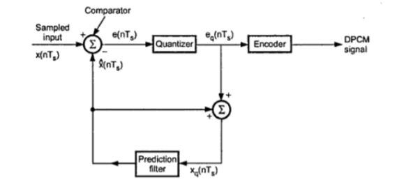
The differential pulse code modulation works on the principle of prediction. The value of the present sample is predicted from the past samples. The prediction may not be exact but it is very close to the actual sample value. The figure shows the transmitter of DPCM system. The sampled signal is denoted by x(nTs) and the predicted signal is  (nTs). The comparator finds out the difference between the actual sample value x(nTs) and predicted sample value is
  (nTs). This is called error and is denoted by e(nTs) . It can be defined as
e(nTs) = x(nTs) -  (nTs)-----------------------------------------------------------------(1)
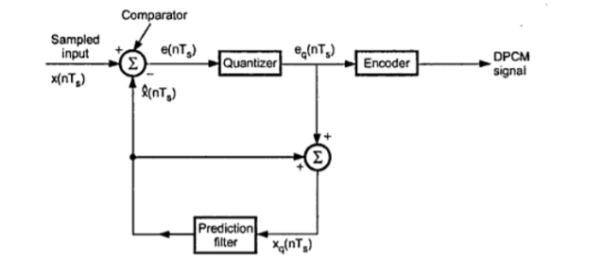
Thus, the error is the difference between unquantized input sample x(nTs) and prediction of it  (nTs). The predicted value is produced by using a prediction filter. The quantizer output signal eq(nTs) and previous prediction is added and given as input to the prediction filter. This signal is called xq(nTs). This makes the prediction more and more close to the actual sampled signal. We can see that the quantized error signal eq(nTs) is too small and can be encoded by using small number of bits. Thus, the number of bits per sample are reduced in DPCM.
The quantizer output can be written as,
Eq(nTs) = e(nTs) + q(nTs) --------------------------------------(2)
Where q(nTs) is the quantization error. As shown in figure the prediction filter input xq(nTs) is obtained by sum  (nTs) and quantizer output that is
Xq(nTs) =  (nTs) + eq(nTs) ---------------------------------(3)
Putting the value of eq(nTs) we get
Xq(nTs) =  (nTs) + e(nTs) + q(nTs) --------------------------------(4)
Equation(1) is written as
e(nTs) = x(nTs) -  (nTs)----------------------------------------------------(5)
e(nTs) +  (nTs) = x(nTs)
Putting the value of e(nTs) +  (nTs) from the above equation we get
Xq(nTs) = x(nTs) +q(nTs)-------------------------------------------------(6)
Thus the quantized version of the signal xq(nTs) is the sum of the original sample value and quantization error q(nTs) . The quantization error can be positive or negative. Thus eq(6) does not depend on the prediction filter characteristics.
Reconstruction of DPCM signal
The figure shows the block diagram of DPCM receiver.

The decoder first reconstructs the quantized error signal from incoming binary signal. The prediction filter output and quantized error signals are summed up to give the quantized version of the original signal. Thus the signal at the receiver differs from the actual signal by quantization error q(nTs) which is introduced permanently in the reconstructed signal.
8. Write a short note on delta modulation?
PCM transmits all the bits which are used to code the sample. Hence the signalling rate and transmission channel bandwidth are large in PCM. To overcome this problem Delta Modulation is used.
Delta modulation transmits only one bit per sample. That is the present sample value is compared with the previous sample value and the indication whether the amplitude is increased or decreased is sent. This step size is fixed. The difference between the input signal x(t) and staircase approximated signal confined to two levels that is δ and -δ. If the difference is positive then the approximated signal is increased by one step that is δ.
If the difference is negative then the approximated signal is reduced by δ.
When the step is reduced ‘0’ is transmitted and if the step is increased ,’1’ is transmitted. Thus for each sample only one binary bit is transmitted .
The figure shows the analog signal x(t) and its staircase approximated signal by delta modulator.
DM Transmitter
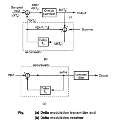
Fig (a) shows the transmitter. The summer in the accumulator adds quantizer output ( δ) with the previous sample approximation. This gives the present sample approximation. That is
u(nTs) = u(nTs-Ts) + [
= u[(n-1)Ts+b(nTs)] ---------------------------------------------------(5)
The previous sample approximation u[(n-1)Ts] is restored by delaying one sample period Ts. The sampled input signal x(nTs) and staircase approximated signal  (nTs) are subtracted to get error signal e(nTs).
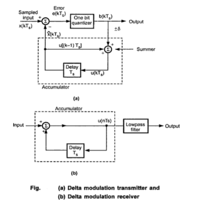
Depending on the sign of e(nTs) one bit quantizer produces an output step of +δ or -δ. If the step size is +δ then binary ‘1’ is transmitted and if it is -δ then binary ‘0’ is transmitted.
DM Receiver
At the receiver as shown in figure(b) the accumulator and low pass filter are used. The accumulator generates the staircase approximated signal output and is delayed by one sampling period Ts. It is then added to the input signal . If input is binary ‘1’ then it adds +δ step to the previous output(which is delayed). If the input is binary ‘0’ then one step ‘δ’ is subtracted from the delayed signal. The lowpass filter has cut-off frequency equal to the highest frequency in x(t). This filter smoothen the staircase signal to reconstruct x(t).
9. Explain Adaptive Delta modulation?
Operating Principle
To overcome the quantization errors due to slope and overload and granularnoise, the noise, the step size is made adaptive to variations in the input singal
  , the step size is incresed. When the input is varying slowly, the step size is reduced. Then the methaod is called
  (ADM)
(ADM)
The adaptive delta modulators can take continuous changes in step size or discrete changes in step size
Transmitter and Reciver
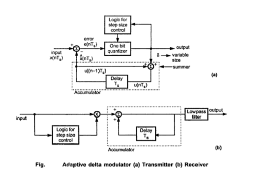
Fig. (a) shows the transmitter and modulator (b) shows reciver of adaptive delta modulator
The logic for step size control is added in the digram. The step size increases or decreases according to certain rule depending on one bit quantizer output.
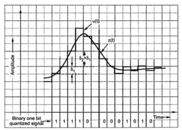
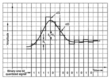
For example if one bit quantizeroutput is high (1), then step size may be doubled for next sample. If one bit quantizer output is low, then step size may be reduced by one step. Fig. shows the waveforms of adaptive delta modulator and sequence of bits transmitted.
In the reciver of adaptive delta modulator shown in the figure (b) the first part generates the step size. The previous input and present input decides the step size. It is then given to an accumulator which builds up staircase waveform. The low-pass filter then smoothenes out the staircase waveform to reconstruct the smooth signal.
10. What are the advantages of Adaptive delta modulation?
- The signal to noise ratio is better than ordinary delta modulation because of the reduction in slope overload distortion and granular noise.
- Because of the variable step size the dynamic range of ADM is wide.
- Utilization of bandwidth is better than delta modulation
Unit 5
Digital Representation of Analog Signals
- What is quantization of signals?
Quantization is representing the sampled values of the amplitude by a finite set of levels, which means converting a continuous-amplitude sample into a discrete-time signal
Both sampling and quantization result in the loss of information.
The quality of a Quantizer output depends upon the number of quantization levels used.
The discrete amplitudes of the quantized output are called as representation levels or reconstruction levels.
The spacing between the two adjacent representation levels is called a quantum or step-size.
2. Explain Quantization error?
Because of quantization inherent errors are introduced in the signal. This error is called quantization error. The quantization error is defined as
 = xq(nTs) – x(nTs) --------------------------------------------(1)
Let an input x(nTs) be of continuous amplitude in the range -xmax to + xmax .
Therefore the total amplitude range becomes,
Total amplitude range = xmax – (-max) --------------------------------------------(2)
= 2 xmax
If the amplitude range is divided into ‘q’ levels of the quantizer then the step size δ is given by
δ= xmax –(-xmax) /q = 2xmax/q -------------------------------------------------------(3)
If the signal x(t) is normalized to mimimum and maximum values equal to 1 then
Xmax = 11
-xmax = -1
Therefore step size will be
δ=2/q (for normalized signal)
3. Explain uniform and non-uniform quantization?
There are two types of uniform quantization
-Mid rise type
-Mid tread type
The following represent two types of uniform quantization

The mid-rise is so called because the origin lies in the middle of a raising part of the stair-case like graph. The quantization levels in this type are even in number.
The mid-tread is so called because the origin lies in the middle of a tread of the stair-case like graph. The quantization levels in this type are odd in number.
Both mid-rise and mid-tread type of uniform quantizer is symmetric about the origin.
Non-Uniform Quantization
In non-uniform quantization the step size is not fixed. It varies according to certain law or as per input signal amplitude. The following fig shows the characteristics of Non-uniform quantizer.
In this figure that step size is small at low input signal levls. Hence qunatization erroe is also small at these inputs. Therefore signal to quantization noise power ratio is improved at low signal levels. Stepsize is higher at high input levels. Hence signal to noise power ratio remains almost same throughout the dynamic range of quantizer.
4. Explain companding?
Non-uniform quantizers are difficult to make and expensive.
• An alternative is to first pass the speech signal through nonlinearity before quantizing with a uniform quantizer.
• The nonlinearity causes the signal amplitude to be compressed. – The input to the quantizer will have a more uniform distribution.
• At the receiver, the signal is expanded by an inverse to the nonlinearity.
• The process of compressing and expanding is called Companding
5. Explain μ-law and A-law companding?
Normally for speech and music signals a μ-law compression is used. This compression is defined by the following equation
Z(x) = (Sgn x) ln(1+μ|x|)/ ln(1+μ) |x|  1
1
Below fig shows the variation of signal to noise ratio with respect to signal level without companding and with companding.
PCM performance with μ-law companding
A-law for companding
The A law provides piecewise compressor characteristic. It has linear segment for low level inputs and logarithmic segment for high level inputs. It is defined as
Z(x) = { A|x|/ 1 + ln A for 0
1 + ln(A|x|)/ 1 + ln A for 1/a  |x|
|x|  1
1
When A=1 we get uniform quantization. The practical value for A is 87.56. Both A-law and μ-law companding is used for PCM telephone systems.
6. Explain the generation and reconstruction of PCM system?
In Pulse Code Modulation, the message signal is represented by a sequence of coded pulses. This message signal is achieved by representing the signal in discrete form in both time and amplitude.
The transmitter section of a Pulse Code Modulator circuit consists of Sampling, Quantizing and Encoding, which are performed in the analog-to-digital converter section. The low pass filter prior to sampling prevents aliasing of the message signal.
The basic operations in the receiver section are regeneration of impaired signals, decoding, and reconstruction of the quantized pulse train. Figure shows the block diagram of PCM which represents the basic elements of both the transmitter and the receiver sections.
Low Pass Filter
This filter eliminates the high frequency components present in the input analog signal which is greater than the highest frequency of the message signal, to avoid aliasing of the message signal.
Sampler
This is the technique which helps to collect the sample data at instantaneous values of message signal to reconstruct the original signal. The sampling rate must be greater than twice the highest frequency component W of the message signal, in accordance with the sampling theorem.
Quantizer
Quantizing is a process of reducing the excessive bits and confining the data. The sampled output when given to Quantizer, reduces the redundant bits and compresses the value.
Encoder
The digitization of analog signal is done by the encoder. It designates each quantized level by a binary code. The sampling done here is the sample-and-hold process. These three sections LPF, Sampler, and Quantizer will act as an analog to digital converter. Encoding minimizes the bandwidth used.
Regenerative Repeater
This section increases the signal strength. The output of the channel also has one regenerative repeater circuit, to compensate the signal loss and reconstruct the signal, as well as to increase its strength.
Decoder
The decoder circuit decodes the pulse coded waveform to reproduce the original signal. This circuit acts as the demodulator.
Reconstruction Filter
After the digital-to-analog conversion is done by the regenerative circuit and the decoder, a low-pass filter is employed, called as the reconstruction filter to get back the original signal.
Hence, the Pulse Code Modulator circuit digitizes the given analog signal, codes it and samples it, and then transmits it in an analog form. This whole process is repeated in a reverse pattern to obtain the original signal.
7. Write a short note on DPCM?
DPCM Transmitter:
The differential pulse code modulation works on the principle of prediction. The value of the present sample is predicted from the past samples. The prediction may not be exact but it is very close to the actual sample value. The figure shows the transmitter of DPCM system. The sampled signal is denoted by x(nTs) and the predicted signal is  (nTs). The comparator finds out the difference between the actual sample value x(nTs) and predicted sample value is
  (nTs). This is called error and is denoted by e(nTs) . It can be defined as
e(nTs) = x(nTs) -  (nTs)-----------------------------------------------------------------(1)
Thus, the error is the difference between unquantized input sample x(nTs) and prediction of it  (nTs). The predicted value is produced by using a prediction filter. The quantizer output signal eq(nTs) and previous prediction is added and given as input to the prediction filter. This signal is called xq(nTs). This makes the prediction more and more close to the actual sampled signal. We can see that the quantized error signal eq(nTs) is too small and can be encoded by using small number of bits. Thus, the number of bits per sample are reduced in DPCM.
The quantizer output can be written as,
Eq(nTs) = e(nTs) + q(nTs) --------------------------------------(2)
Where q(nTs) is the quantization error. As shown in figure the prediction filter input xq(nTs) is obtained by sum  (nTs) and quantizer output that is
Xq(nTs) =  (nTs) + eq(nTs) ---------------------------------(3)
Putting the value of eq(nTs) we get
Xq(nTs) =  (nTs) + e(nTs) + q(nTs) --------------------------------(4)
Equation(1) is written as
e(nTs) = x(nTs) -  (nTs)----------------------------------------------------(5)
e(nTs) +  (nTs) = x(nTs)
Putting the value of e(nTs) +  (nTs) from the above equation we get
Xq(nTs) = x(nTs) +q(nTs)-------------------------------------------------(6)
Thus the quantized version of the signal xq(nTs) is the sum of the original sample value and quantization error q(nTs) . The quantization error can be positive or negative. Thus eq(6) does not depend on the prediction filter characteristics.
Reconstruction of DPCM signal
The figure shows the block diagram of DPCM receiver.

The decoder first reconstructs the quantized error signal from incoming binary signal. The prediction filter output and quantized error signals are summed up to give the quantized version of the original signal. Thus the signal at the receiver differs from the actual signal by quantization error q(nTs) which is introduced permanently in the reconstructed signal.
8. Write a short note on delta modulation?
PCM transmits all the bits which are used to code the sample. Hence the signalling rate and transmission channel bandwidth are large in PCM. To overcome this problem Delta Modulation is used.
Delta modulation transmits only one bit per sample. That is the present sample value is compared with the previous sample value and the indication whether the amplitude is increased or decreased is sent. This step size is fixed. The difference between the input signal x(t) and staircase approximated signal confined to two levels that is δ and -δ. If the difference is positive then the approximated signal is increased by one step that is δ.
If the difference is negative then the approximated signal is reduced by δ.
When the step is reduced ‘0’ is transmitted and if the step is increased ,’1’ is transmitted. Thus for each sample only one binary bit is transmitted .
The figure shows the analog signal x(t) and its staircase approximated signal by delta modulator.
DM Transmitter
Fig (a) shows the transmitter. The summer in the accumulator adds quantizer output ( δ) with the previous sample approximation. This gives the present sample approximation. That is
u(nTs) = u(nTs-Ts) + [
= u[(n-1)Ts+b(nTs)] ---------------------------------------------------(5)
The previous sample approximation u[(n-1)Ts] is restored by delaying one sample period Ts. The sampled input signal x(nTs) and staircase approximated signal  (nTs) are subtracted to get error signal e(nTs).
Depending on the sign of e(nTs) one bit quantizer produces an output step of +δ or -δ. If the step size is +δ then binary ‘1’ is transmitted and if it is -δ then binary ‘0’ is transmitted.
DM Receiver
At the receiver as shown in figure(b) the accumulator and low pass filter are used. The accumulator generates the staircase approximated signal output and is delayed by one sampling period Ts. It is then added to the input signal . If input is binary ‘1’ then it adds +δ step to the previous output(which is delayed). If the input is binary ‘0’ then one step ‘δ’ is subtracted from the delayed signal. The lowpass filter has cut-off frequency equal to the highest frequency in x(t). This filter smoothen the staircase signal to reconstruct x(t).
9. Explain Adaptive Delta modulation?
Operating Principle
To overcome the quantization errors due to slope and overload and granularnoise, the noise, the step size is made adaptive to variations in the input singal
  , the step size is incresed. When the input is varying slowly, the step size is reduced. Then the methaod is called
  (ADM)
(ADM)
The adaptive delta modulators can take continuous changes in step size or discrete changes in step size
Transmitter and Reciver
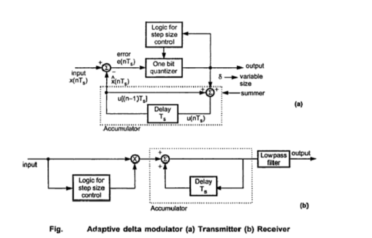
Fig. (a) shows the transmitter and modulator (b) shows reciver of adaptive delta modulator
The logic for step size control is added in the digram. The step size increases or decreases according to certain rule depending on one bit quantizer output.
For example if one bit quantizeroutput is high (1), then step size may be doubled for next sample. If one bit quantizer output is low, then step size may be reduced by one step. Fig. shows the waveforms of adaptive delta modulator and sequence of bits transmitted.
In the reciver of adaptive delta modulator shown in the figure (b) the first part generates the step size. The previous input and present input decides the step size. It is then given to an accumulator which builds up staircase waveform. The low-pass filter then smoothenes out the staircase waveform to reconstruct the smooth signal.
10. What are the advantages of Adaptive delta modulation?
- The signal to noise ratio is better than ordinary delta modulation because of the reduction in slope overload distortion and granular noise.
- Because of the variable step size the dynamic range of ADM is wide.
- Utilization of bandwidth is better than delta modulation