Unit - 5
Real Word Interfacing With 18FXXXX
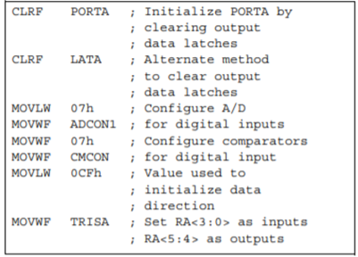
Q1) WAP in assembly language such that bits in TRISA register are set when using them as analog inputs?
A1)
The TRISA register controls PORTA pins direction while being used as analog inputs. The user must ensure that the bits in TRISA register are set when using them as analog inputs.
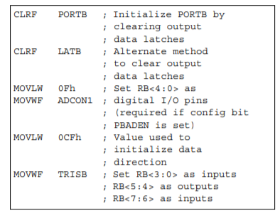
Q2) WAP in assembly language for initialising PORTB?
A2)
PORTB is an 8-bit wide, bidirectional port. The Data Direction register is TRISB. When TRISB bit (= 1) then PORTB pin serves as input.Clearing a TRISB bit (= 0) PORTB pin serves as output. The Data Latch register (LATB) is memory mapped. Read-modify-write operations on LATB register read and write the latched output value for PORTB
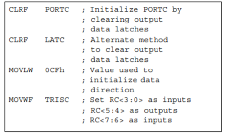
Q3) Write the assembly language program for initializing PORTC?
A3)
PORTC is an 8-bit wide, bidirectional port. The Data Direction register is TRISC. Setting a TRISC bit (= 1) will make PORTC pin an input. Clearing a TRISC bit (= 0) will make the PORTC pin an output. The Data Latch register (LATC) is memory mapped. Read-modify-write operations on LATC register read and write the latched output value for PORTC. When enabling peripheral functions, define TRIS bits for each PORTC pin. Some peripherals override TRIS bit to make the pin an output, while other peripherals override the TRIS bit to make the pin as input.
Q4) Write a program in C for interfacing LED with microcontroller PIC 18 family?
A4)
#include<p18f4520.h>
Void DELAY();
#pragma config OSC=HS
#pragma config PWRT=OFF
#pragma config WDT=OFF
#pragma config DEBUG=OFF, LVP=OFF
Void main()
{
TRISDbits.RD0 = 0x00; //set RD0 pin direction as an output
While(1) //forever loop
{
PORTDbits.RD0=0X01; //set RD0 pin as HIGH
DELAY(); //call delay
PORTDbits.RD0=0X00; //CLEAR RD0 piN
DELAY(); //call delay
}
}
Void DELAY()
{
Unsigned int i;
For(i=0;i<10000;i++);
}
Q5) Write an Embedded C Program to display word "AB " using 8-bit mode
A5)
#include<p18f4520.h>
#pragma config OSC=HS
#pragma config PWRT=OFF
#pragma config WDT=OFF
#pragma config DEBUG=OFF, LVP=OFF
Void lcdcmd(unsigned char value);//Function Prototype declaration
Void lcddata(unsigned char value);
Void msdelay(unsigned int itime);
#define ldata PORTD //Declare ldata variable for PORTD
#define rs PORTEbits.RE0 //Declare rs variable for pin RE0
#define rw PORTEbits.RE1 //Declare rw variable for pin RE1
#define en PORTEbits.RE2 //Declare en variable for pin RE2
Void main()
{
TRISD = 0x00; //Set direction of PORTD as output
ADCON1=0X0F;
TRISE=0X00; //set direction of PORTE as output
Msdelay(50);
Lcdcmd(0x38); //16x2 LCD
Msdelay(50);
Lcdcmd(0x0E);
Msdelay(15);
Lcdcmd(0x01); //clear Display screen
Msdelay(15);
Lcdcmd(0x06); //Increment cursor and shift right
Msdelay(15);
Lcdcmd(0x80); //Force cursor on first row first position
Lcddata('S'); //Display character 'S'
Msdelay(50);
Lcddata('K'); //Display character 'K'
Msdelay(50);
}
Void lcdcmd (unsigned char value)
{
Ldata=value; //Send the command value to PORTD
Rs=0; //selection of command register of LCD
Rw=0;
En=1; //Generate High to Low pulse on Enable pin
Msdelay(1);
En=0;
}
Void lcddata (unsigned char value)
{
Ldata=value; //Send the command value to PORTD
Rs=1; //selection of DATA register of LCD
Rw=0;
En=1; //Generate High to Low pulse on Enable pin
Msdelay(1);
En=0;
}
Void msdelay (unsigned int itime)
{
Int i,j;
For(i=0;i<itime;i++)
For(j=0;j<135;j++);
}
Q6) Write embedded program in C for interfacing keyboard with PIC?
A6)
#include <pic18f4550.h>
#include "Configuration_Header_File.h"
#include "16x2_LCD_4bit_File.h"
Unsigned char keyfind(); /* function to find pressed key */
#define write_portLATB /* latch register to write data on port */
#define read_portPORTB /* PORT register to read data of port */
#define Direction_Port TRISB
Unsigned char col_loc,rowloc,temp_col;
Unsigned char keypad[4][4]= {'7','8','9','/',
'4','5','6','*',
'1','2','3','-',
' ','0','=','+'};
Void main()
{
Char key;
OSCCON = 0x72;
RBPU=0; /* activate pull-up resistor */
LCD_Init(); /* initialize LCD16x2 in 4-bit mode */
LCD_String_xy(0,0,"Press a Key");
LCD_Command(0xC0); /* display pressed key on 2nd line of LCD */
While(1)
{
Key = keyfind(); /* find a pressed key */
LCD_Char(key); /* display pressed key on LCD16x2 */
}
}
Unsigned char keyfind()
{
Direction_Port = 0xf0; /* PORTD.0-PORTD.3 as a Output Port and PORTD.4-PORTD.7 as a Input Port*/
Unsigned char temp1;
Write_port = 0xf0; /* Make lower nibble as low(Gnd) and Higher nibble as High(Vcc) */
Do
{
Do
{
Col_loc = read_port& 0xf0; /* mask port with f0 and copy it to col_loc variable */
}while(col_loc!=0xf0); /* Check initially at the start there is any key pressed*/
Col_loc = read_port& 0xf0; /* mask port with f0 and copy it to col_loc variable */
}while(col_loc!=0xf0);
MSdelay(50);
Write_port = 0xf0; /* Make lower nibble as low(Gnd) and Higher nibble as High(Vcc) */
Do
{ do
{
Col_loc = read_port& 0xf0;
}while(col_loc==0xf0); /* Wait for key press */
Col_loc = read_port& 0xf0;
}while(col_loc==0xf0); /* Wait for key press */
MSdelay(20);
Col_loc = read_port& 0xf0;
While(1)
{
Write_port = 0xfe; /* make Row0(D0) Gnd and keep other row(D1-D3) high */
Col_loc = read_port& 0xf0; /* Read Status of PORT for finding Row */
Temp_col=col_loc;
If(col_loc!=0xf0)
{
Rowloc=0; /* If condition satisfied get Row no. Of key pressed */
While(temp_col!=0xf0) /* Monitor the status of Port and Wait for key to release */
{
Temp_col = read_port& 0xf0; /* Read Status of PORT for checking key release or not */
}
Break;
}
Write_port = 0xfd; /* make Row1(D1) Gnd and keep other row(D0-D2-D3) high */
Col_loc = read_port& 0xf0; /* Read Status of PORT for finding Row */
Temp_col=col_loc;
If(col_loc!=0xf0)
{
Rowloc=1; /* If condition satisfied get Row no. Of key pressed*/
While(temp_col!=0xf0) /* Monitor the status of Port and Wait for key to release */
{
Temp_col = read_port& 0xf0; /* Read Status of PORT for checking key release or not */
}
Break;
}
Write_port = 0xfb; /* make Row0(D2) Gnd and keep other row(D0-D1-D3) high */
Col_loc = read_port& 0xf0; /* Read Status of PORT for finding Row*/
Temp_col=col_loc;
If(col_loc!=0xf0)
{
Rowloc=2; /* If condition satisfied get Row no. Of key pressed */
While(temp_col!=0xf0) /* Wait for key to release */
{
Temp_col = read_port& 0xf0; /* Read Status of PORT for checking key release or not */
}
Break;
}
Write_port = 0xf7; /* make Row0(D3) Gnd and keep other row(D0-D2) high */
Col_loc = read_port& 0xf0; /* Read Status of PORT for finding Row */
Temp_col=col_loc;
If(col_loc!=0xf0)
{
Rowloc=3; /* If condition satisfied get Row no. Of key pressed */
While(temp_col!=0xf0) /* Wait for key to release */
{
Temp_col = read_port& 0xf0; /* Read Status of PORT for checking key release or not */
}
Break;
}
}
While(1)
{
If(col_loc==0xe0)
{
Return keypad[rowloc][0]; /* Return key pressed value to calling function */
}
Else
If(col_loc==0xd0)
{
Return keypad[rowloc][1]; /* Return key pressed value to calling function */
}
Else
If(col_loc==0xb0)
{
Return keypad[rowloc][2]; /* Return key pressed value to calling function */
}
Else
{
Return keypad[rowloc][3]; /* Return key pressed value to calling function */
}
}
MSdelay(300);
}
Q7) WAP in assembly language for Interfacing of PIR sensor?
A7)
The circuit will read the status of the output of the PIR sensor and switch ON the LED when there is a motion detected and switch OFF the LED when there is no motion detected.
Output pin of the PIR sensor is connected to Port 3.5 pin of the 8051. Resistor R1, capacitor C1 and push button switch S1 forms the reset circuit. Capacitors C3,C4 and crystal X1 are associated with the oscillator circuit.
C2 is just a decoupling capacitor. LED is connected through Port 2.0 of the microcontroller. Transistor Q1 is used for switching the LED. R2 limits the base current of the transistor and R3 limits the current through the LED.
Program:
PIR EQU P3.5
LED EQU P2.0
ORG 00H
CLR P2.0
SETB P3.5
HERE:JNB PIR, HERE
SETB LED
HERE1:JB PIR,HERE1
CLR LED
SJMP HERE
END
Q8) Write assembly language program for sending continuous values to the DAC for producing a sine wave?
A8)
The below program sends the values to the DAC continuously to produce a sine wave.
OVER MOVLW upper(TABLE)
MOVWF TBLPTRU
MOVLW high(TABLE)
MOVWF TBLLPTRH
MOVLW low(TABLE)
MOVWF TBLPTRL
AGAIN TBLRD
MOVF TABLAT, W
XORLW 0X0
BZ OVER
MOVWF PORTB
INCF TBLPTRL, F
BRA AGAIN
ORG 0X250
TABLE: DB D’128’, D’192’, D’238’, D’255’, D’238’, D’192’
DB D’128’, D’64’, D’17’, D’1’, D’17’, D’64’, D’0’
END
Q9) Write C language program for sending continuous values to the DAC for producing a sine wave?
A9)
#include<p18F458.h>
Rom const unsigned char WAVEVALUE [12] = {128, 192, 238, 255, 238, 192, 128, 64, 17, 0, 17, 64}
Void main ()
{
Unsigned char x;
TRISB=0;
While(1)
{
For (x=0;x<12;x++)
PORTB= WAVEVALUE [x];
}
}
Q10) Design of PIC test board for verifying the LED connected to port B, with switches and Buzzer to port D, with relay interface for Port A. Write C language program for this.
A10)
#include<P18F4550.h>
void delay(void);
void main()
{
unsigned char i, key;
TRISDbits.TRISD0 = 1;//set RD0 as input
TRISBbits.TRISB0 = 0;//set LED pin RB0 as output
TRISDbits.TRISD2 = 0;//set buzzer pin RD2 as output
TRISAbits.TRISA4 = 0;//set relay pin RA4 as output
while(1)
{
LATDbits.LD0 = 1; // RD0 pin as continuosly High
if(PORTDbits.RD0 == 0) // if switch is pressed
{
PORTBbits.RB0 = 1;//set led pin RB0 as High
delay();
PORTDbits.RD2 = 1;//set buzzer pin RD2 as High, Buzzer ON
delay();
PORTAbits.RA4 = 1;//set relay pin RA4 as High, Relay ON
delay();
}
else(PORTDbits.RD0 == 1) // if switch is pressed
{
PORTBbits.RB0 = 0;//set led pin RB0 as low, led off
delay();
PORTDbits.RD2 = 0;//set buzzer pin RD2 as low, Buzzer off
delay();
PORTAbits.RA4 = 0;//set relay pin RA4 as low, Relay Off
delay();
}
}
void delay()
{
unsigned int j,k;
for(j=0;j<=10;j++)
for(k=0;k<=3000;k++);
}
Q11) Design a Home protection system to for indicating various parameters like temperature, door open /closed, internal apparatus on, which will give alert by indicator, display and sounding alarm if exceed the set point. Also make provision to store few current records in the serial memory for analysis.
A11)
- Design of Power Supply

Figure. Design of Power Supply
The microcontroller selected is PIC 18F4550 which works on the frequency of oscillator ranging from 0 to 20 MHz and requires power supply of ± 5 or ±12 V. A simple circuit design for +5 V is shown in Figure.
- Design of clock circuit
The Quartz crystal is connected to OSC1 and OSC2 pin in order to synchronize the operation of all components connected with internal and external means. The values for C1 and C2 are selected according to the crystal frequency for stabilizing the oscillator pulses. In general, with quartz crystal 22-33 µF is preferred
- Design of Reset
The RC high pass filter with C=0.1µF along with 20 kΩ register is connected to MCLR pin. When high pulse appear on it, resets the contents of inter registers and SFRS to initial value.
PIC has 33 I/O lines which can be configured as input and out using TRISX register.
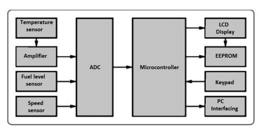
Figure. Block Diagram
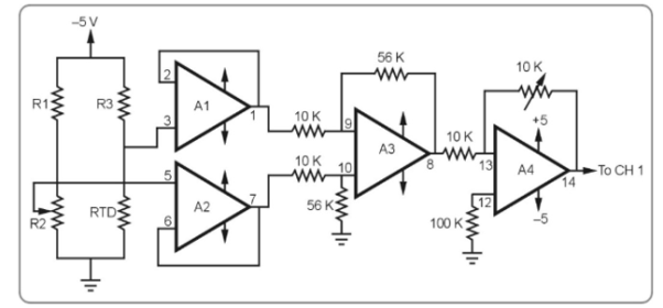
Figure. Signal Conditioning using Op-amp
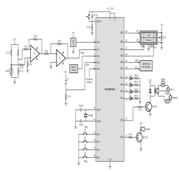
Figure. Interfacing Diagram for Home Protection system
Q12) Design of PIC test board for verifying the LED connected to port B, with switches and Buzzer to port D, with relay interface for Port A.
A12)
The steps involved are:
- Design of Power Supply
- Design of clock circuit
- Design of Reset Circuit.
- Configuration of port
- Interfacing Diagram
- Program.
- Design of Power Supply
PIC 18F4550 works on the frequency of oscillator ranging from 0 to 20 MHz and requires power supply of ± 5 or ±12 V. A simple circuit design for +5 V is shown in Fig.

Figure. Design of +5V Power Supply
- Design of clock circuit
The Quartz crystal is connected to OSC1 and OSC2 pin in order to synchronize the operation of all components connected with internal and external means. The values for C1 and C2 are selected according to the crystal frequency for stabilizing the oscillator pulses. In general, with quartz crystal 22-33 µF is preferred.
- Design of Reset Circuit
The RC high pass filter with C=0.1µF along with 20 kΩ register is connected to MCLR pin. When high pulse appear on it, resets the contents of inter registers and SFRS to initial value.
- Configuration of port
PIC has 33 I/O lines which can be configured as input and output using TRISX register as
- If TRISX = 0 —Ports (A-E) are configured as output ports
- If TRISX = 1 —Ports (A-E) are configured as input ports.
- Interfacing
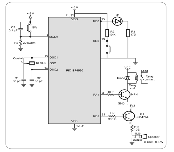
Figure. Minimum Connection PIC test board
Q13) What are DAC circuits. Explain interfacing with PIC?
A13)
In these systems the microcontroller generates output in digital form, The controlling system requires analog signal because they don't accept digital data. Hence, there is a need to use DAC which converts digital data into its equivalent analog voltage.
In the figure shown, we use 8-bit DAC 0808. This IC converts digital data into its equivalent analog current. The I to V converter converts the current into its equivalent voltage.
According to theory of DAC Equivalent analog output is given as:
 :
:
1. IF data =00H [00000000] and
Vref = 10V

Therefore, V0= 0 Volts.
2. If data is 80H [10000000],
And Vref = 10V

Therefore, V0= 5 Volts.
Different Analog output voltages for different Digital signal is given as:
DATA | OUTPUT VOLTAGE |
00H | 0V |
80H | 5V |
FFH | 10V |
Interfacing Diagram
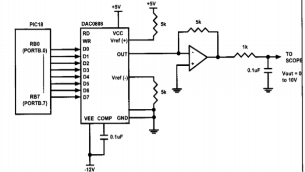
Figure. Interfacing PIC with DAC 0808
Q14) Draw the interfacing diagram for interfacing of PIR sensor and explain the circuit operation?
A14)
PIR sensors are widely used in motion detecting devices. It measures the amount of infrared energy radiated by objects in front of it.
They do not emit any kind of radiation but sense the infrared waves emitted or reflected by objects.
The heart of a PIR sensor is a solid- state sensor or an array of such sensors constructed from pyro-electric materials.
Pyro-electric material is material by virtue of it generates energy when exposed to radiation.
Suitable signal conditioning circuits convert the energy generated by the sensor to a suitable voltage output.
The output of a PIR sensor module will be HIGH when there is motion in its field of view and the output will be LOW when there is no motion.
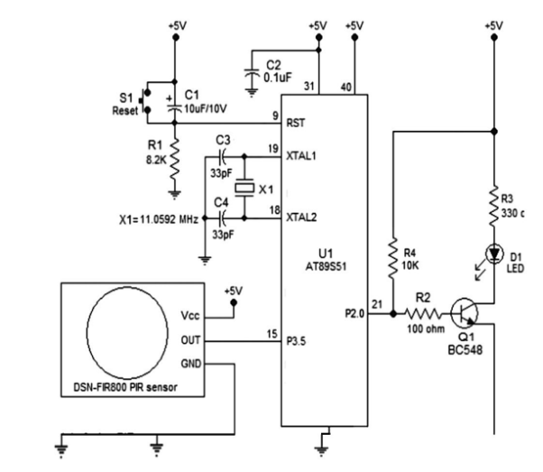
Figure. Interfacing of PIR sensor.
The output voltage will be 3.3V when the motion is detected and 0V when there is no motion. The sensing angle cone is 110° and the sensing range is 7 meters. The default delay time is 5 seconds. There are two preset resistor on the sensor module. One is used for adjusting the delay time and the other is used for adjusting the sensitivity.
Circuit Operation:
The circuit will read the status of the output of the PIR sensor and switch ON the LED when there is a motion detected and switch OFF the LED when there is no motion detected.
Output pin of the PIR sensor is connected to Port 3.5 pin of the 8051. Resistor R1, capacitor C1 and push button switch S1 forms the reset circuit. Capacitors C3,C4 and crystal X1 are associated with the oscillator circuit.
C2 is just a decoupling capacitor. LED is connected through Port 2.0 of the microcontroller. Transistor Q1 is used for switching the LED. R2 limits the base current of the transistor and R3 limits the current through the LED.
Q15) WAP in assembly language such that bits in MCLRE configuration bit are set when using them as analog inputs of PORTE?
A15)
The fourth pin of PORTE (MCLR/VPP/RE3) is an input pin. Its operation is controlled by MCLRE configuration bit. When selected as port pin (MCLRE = 0), it functions as digital input pin; Otherwise, it functions as the device’s Master Clear input. In either configuration, RE3 functions as programming voltage input during programming.
CLRF PORTE ; Initialize PORTE by
; clearing output
; data latches
CLRF LATE ; Alternate method
; to clear output
; data latches
MOVLW 0Ah ; Configure A/D
MOVWF ADCON1 ; for digital inputs
MOVLW 03h ; Value used to
; initialize data
; direction
MOVWF TRISD ; Set RE<0> as inputs
; RE<1> as outputs
; RE<2> as inputs
Q16) Write program to configure PORTD pin an input pin?
A16)
PORTD is an 8-bit wide, bidirectional port. The corresponding Data Direction register is TRISD. Setting a TRISD bit (= 1) will make the corresponding PORTD pin an input. Clearing a TRISD bit (= 0) will make the corresponding PORTD pin an output. The Data Latch register (LATD) is also memory mapped. Read-modify-write operations on the LATD register read and write the latched output value for PORTD.
CLRF PORTD ; Initialize PORTD by
; clearing output
; data latches
CLRF LATD ; Alternate method
; to clear output
; data latches
MOVLW 0CFh ; Value used to
; Initialize data
; direction
MOVWF TRISD ; Set RD<3.0> as inputs
; RD<5.4> as outputs
; RD<7.6> as inputs
Q17) What are LED diodes explain with internal circuit?
A17)
A light-emitting diode (LED) is a two-lead semiconductor light source. It has p–n junction diode that emits light when activated. When suitable voltage is applied to the leads, electrons recombine with electron holes within the device, releasing energy in the form of photons. This effect is called electroluminescence. The color of light is determined by energy band gap of semiconductor.
When operated in a forward biased direction Light Emitting Diodes are semiconductor devices that convert electrical energy into light energy.
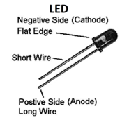
Figure. LED
An LED is interfaced with PIC18FXXX microcontroller for various purpose. The Port Pins are configured in output direction. So, is Logic "1" is at the O/P pin, then LED will be turned "ON" if Logic "0" is given the LED will be turned "OFF".
Simply: Logic "1" -> 5V DC to output pin
Logic "0" -> 0 V to output pin.
LED with common cathode mode can be connected with PIC18FXX along with a resistor.
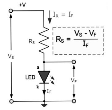
Figure. LED with resistor