Unit 1
Q.1 What is geometric transformation? Explation translation transformation.
A1) “Geometric Transormation is the change of the orientation, shape and size of the geometric model in the database and graphic image in the computer graphics.”

The basic geometric transformation used in modelling in computer graphics are:
a) Translation
b) Shear
c) Rotation
d) Scaling
e) Reflection
Translation:
“Translation is defined as the movement of every point on the geometric model in the same direction by same distance.”

Consider a point  is translated by a distance
  in
in  direction and
  in
in  direction to a new position


The translation is equation is given by

Where,

 Original position of the point

 New position of the point
 Translation matrix
Q.2 What is the need of homogeneous transformation?
A2)
Q.3 What is concatenated transformation?
A3) A number of transformations or sequence of transformations can be combined into single one called as composition. The resulting matrix is called as composite matrix. The process of combining is called as concatenation.
Suppose we want to perform rotation about an arbitrary point, then we can perform it by the sequence of three transformations
The ordering sequence of these numbers of transformations must not be changed. The composite transformation is performed by multiplying matrix in order from right to left side.
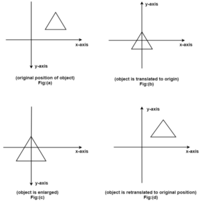
Example showing composite transformations:
The enlargement is with respect to center. For this following sequence of transformations will be performed and all will be combined to a single one
Step1: The object is kept at its position as in fig (a)
Step2: The object is translated so that its center coincides with the origin as in fig (b)
Step3: Scaling of an object by keeping the object at origin is done in fig (c)
Step4: Again translation is done. This second translation is called a reverse translation. It will position the object at the origin location.

Mathematical representation of composite
Transformation (Concatenated matrix):

Then the object is scaled
The scaling matrix is given by

Finally, the object is given translated back It becomes inverse translation 

Then the concatenated matrix is given by


and 
Q.4 Explain different coordinate systems.
A4) There are three major types of coordinate system commonly used in CAD modeling.
“The model coordinate system is the reference space of model with respect to which all the geometrical data of model is stored in database.”
This is the only coordinate system that modelling software recognizes when storing or retrieving the graphical information in or from model database.
The CAD software stores the graphical information in the model database with reference to the coordinate system known as model coordinate system.
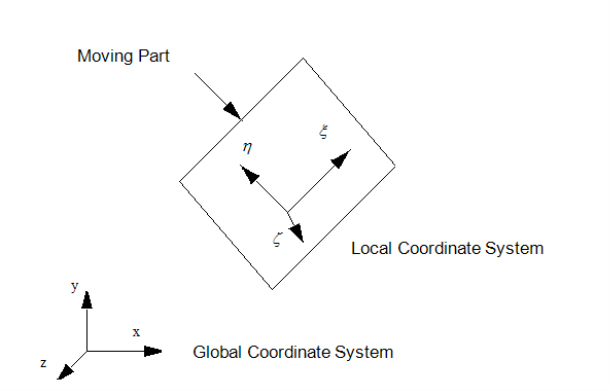
2. User Coordinate System (UCS) or Local Coordinate System or Working Coordinate System (WCS):
“User Coordinate System is defined by the user for the convenience of input of the graphical information.”
In CAD modelling, the user inputs the graphical information with reference to the coordinate system known as user coordinate system.
If the geometric model has a complex geometry or a specific orientation, it is highly inconvenient to input the graphical data in a model coordinate system.

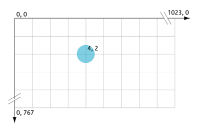
3. Screen Coordinate system:
“Screen Coordinate system is a 2D Cartesian Coordinate System whose origin is located at the corner of the graphics display screen.”
This system is display-device dependent.

Fig. Screen Coordinate System
Q.5 Explain Geometric mapping.
A5) Geometric Mapping:
“Mapping of the Geometric model changes the graphical description of model from one coordinate system to another without changing the position, orientation, size and shape of the model.”
In CAD modelling, the user inputs the graphical information with reference to the working or user coordinate system (UCS or WCS) of the sketch plane, while CAD software stores the graphical information in the model database with reference to Model Coordinate System (MCS).
Mapping is used to convert the coordinates of points on the model from one coordinate system to another.
Types of Geometric Mapping:
“If the axes of the two coordinate systems are parallel, then the mapping is called translation mapping.”
Let, dx = distance of the origin of original system (O) from the origin of the new coordinate system (O’) along X-direction.
dy = distance of the origin of original system (O) from the origin of the new coordinate system (O’) along Y-direction.
Coordinate of point P in new coordinate system are:
x’ = x + dx
y’ = y + dy
 The translation mapping matrix is given by
 Translation mapping matrix

2. Rotational Mapping:
“If both the coordinate systems have common origin but the axes are at an angle, then the mapping is called rotational mapping.”
Let, ɸ = angle made by the axes of original coordinate system with the axes of new coordinate system.
Coordinate of point P in new coordinate system are:
x’ = x cos ɸ - y sin ɸ
y' = x sin ɸ + y cos ɸ
The rotational mapping matrix is given by
 Rotational mapping matrix

3. General Mapping:
“It is the combination of rotational and translational mapping.”
Coordinate of point P in new coordinate system are:
x’ = x cos ɸ - y sin ɸ + dx
y' = x sin ɸ + y cos ɸ + dy
The general mapping matrix is given by:


Q.6 Explain Perspective projection.
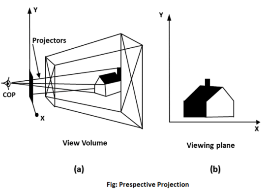
A6) In perspective projection farther away object from the viewer, small it appears. This property of projection gives an idea about depth. The artist use perspective projection from drawing three-dimensional scenes.
Two main characteristics of perspective are vanishing points and perspective foreshortening. Due to foreshortening object and lengths appear smaller from the center of projection. More we increase the distance from the center of projection, smaller will be the object appear.
Vanishing Point:
“It is the point where all lines will appear to meet. There can be one point, two point, and three point perspectives.”
One Point:
“There is only one vanishing point.”
Two Points:
“There are two vanishing points. One is the x-direction and other in the y –direction.”
Three Points:
“There are three vanishing points. One is x second in y and third in two directions.”
In Perspective projection lines of projection do not remain parallel. The lines converge at a single point called a center of projection. The projected image on the screen is obtained by points of intersection of converging lines with the plane of the screen. The image on the screen is seen as of viewer's eye were located at the centre of projection, lines of projection would correspond to path travel by light beam originating from object.
Important terms related to perspective

Q.7 If a point P having coordinates (3,3) is mirrored about X and Y axis, determine new coordinates.
Solution:

Mirror about both axis means mirror about origin.


The new coordinates of point are (-3,-3).
Q.8 An object is to be rotated about point A(-10,-10) by 90o in anti-clockwise direction. Find the concatenated transformation matrix.
Solution:
A(-10,-10) 
The rotation about point A(-10,-10) through  can be achieved in three steps:
Translate the line such that, point A coincides with origin. Hence translation distances are:
tx = 10 and ty = 10

2. Rotation

3. Inverse translation
Translate the line again at point A

Concatenated matrix [CT]


Q.9 A line drawn between P1(2,4) and P2(6,8), is rotated by 30o in CCW direction about point P1. Find the concatenated matrix and new coordinates of the points on the line.
Solution:
P1(2,4) P2(6,8) and 
The rotation about point P1(2,4) through  can be achieved in three steps:
Translate the line such that, point P1 coincides with origin. Hence translation distances are:
tx = -2 and ty = -4

2. Rotation

3. Inverse translation
Translate the line again at point A

Concatenated matrix [CT]


The new position of the line:


The new coordinates of the vertices of the rotated line are P’1 (2,4) and P’2 (3.464,9.464)
Q.10 A triangle defined by points P (2,2) Q(6,2) R(4,4) is created in UCS having x-axis oriented at 45o and located at (4,5) units from MCS. Find coordinates of triangle in MCS.
Solution:
dx = 4 dy = 5  P(2,2) Q(6,2) R(4,4)
General mapping matrix is

Coordinates of vertices of triangle in MCS:


The coordinates of the triangle in MCS are:
P’(4,7.83), Q’(6.83,10.657) and R’(4,10.657)