Unit 3
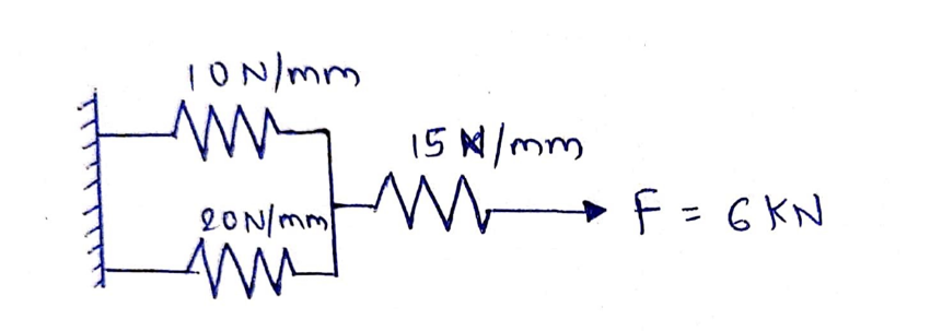
Q.1 Fig shows a cluster of 3 springs. Using finite element method, determine: 1) the deflection of each spring and 2) the reaction force at support.
Solution:
Given: k1 = 10 N/mm
k2 = 20 N/mm
k3 = 15 N/mm
U1 = 0
P3 = 6000 N

Three springs can be treated as three 1D spar element
Element Number | Global Node number ‘n’ of | |
Local Node 1 | Local Node 2 | |
1 | 1 | 2 |
2 | 1 | 2 |
3 | 2 | 3 |
2. Element stiffness matrix
For Element 1,

For Element 2,

For Element 3,

3. Global stiffness matrix


4. Global load vector

5. Global nodal displacement vector

6. Global stiffness-nodal displacement relationship
Hence after the assembly, the equilibrium equation is,

At node 1, U1 = 0, there is rigid support.
Using elimination approach, first rows and columns are eliminated.
7. Nodal Displacements

Solving two equations for two unknowns, we get,
U2 = 200 mm and U3 = 600 mm
Deflection of Spring 1 = U2 – U1 = 200 – 0 = 200 mm
Deflection of Spring 2 = U2 – U1 = 200 – 0 = 200 mm
Deflection of Spring 3 = U3 – U2 = 600 – 200 = 400 mm
8. Reaction force at support
We have,
30U1 – 30U2 = R
30 x 0 – 30 x 200 = R
R = -6000 N
Q.2 Fig shows a cluster of 3 springs having stiffness 10, 20 and 40 N/mm, all connected in parallel. One end of assembly is fixed and force of 700 N is applied at other end. Using finite element method, determine the deflection of each spring.
Solution:
Given: k1 = 10 N/mm
k2 = 20 N/mm
k3 = 40 N/mm
U1 = 0
P2 = 700 N
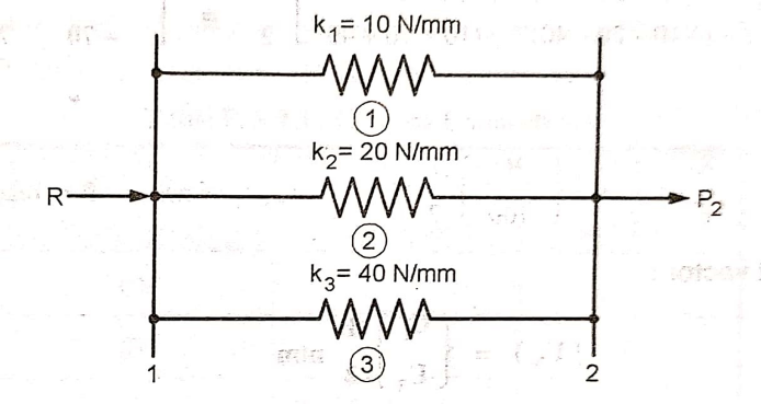
Three springs can be treated as three 1D spar element
Element Number | Global Node number ‘n’ of | |
Local Node 1 | Local Node 2 | |
1 | 1 | 2 |
2 | 1 | 2 |
3 | 1 | 2 |
2. Element stiffness matrix
For Element 1,

For Element 2,

For Element 3,

3. Global stiffness matrix


4. Global load vector

5. Global nodal displacement vector

6. Global stiffness-nodal displacement relationship
Hence after the assembly, the equilibrium equation is,

At node 1, U1 = 0, there is rigid support.
Using elimination approach, first rows and columns are eliminated.
7. Nodal Displacements

Solving the equation, we get,
U2 = 10 mm
Deflection of all Springs = U2 – U1 = 10 – 0 = 10 mm
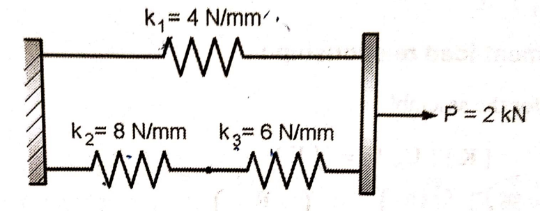
Q.3 Fig shows a cluster of three springs. Using the finite element method, determine:
1) The deflection of each spring
2) The reaction force at support
Solution:
Given: k1 = 4N/mm
k2 = 8N/mm
k3 = 6N/mm
U1 = 0
P3 = 2000 N
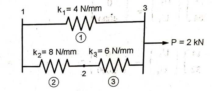
Three springs can be treated as three 1D spar element
Element Number | Global Node number ‘n’ of | |
Local Node 1 | Local Node 2 | |
1 | 1 | 3 |
2 | 1 | 2 |
3 | 2 | 3 |
2. Element stiffness matrix
For Element 1,

For Element 2,

For Element 3,

3. Global stiffness matrix


4. Global load vector

5. Global nodal displacement vector

6. Global stiffness-nodal displacement relationship
Hence after the assembly, the equilibrium equation is,

At node 1, U1 = 0, there is rigid support.
Using elimination approach, first rows and columns are eliminated.
7. Nodal Displacements

Solving two equations for two unknowns, we get,
U2 = 115.38 mm and U3 = 269.23 mm
Deflection of Spring 1 = U3 – U1 = 269.23 – 0 = 269.23 mm
Deflection of Spring 2 = U2 – U1 = 115.38 – 0 = 115.38 mm
Deflection of Spring 3 = U3 – U2 = 269.23 – 115.38 = 153.84 mm
8. Reaction force at support
We have,
12U1 – 8U2 – 4U3 = R
12 x 0 – 8 x 115.38 – 4 x 269.23 = R
R = -2000 N
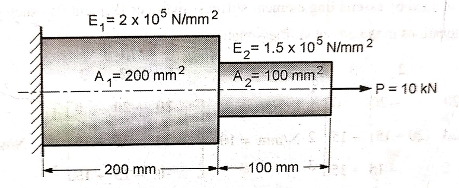
Q.4 An axial step bar is shown in figure. Determine the deflection, stresses in element and reaction force.
Solution:
Given: l1 = 200 mm
l2 = 100 mm
A1 = 200 mm2
A2 = 100 mm2
E1 = 2 x 10⁵ N/ mm2
E2 = 1.5 x 10⁵ N/ mm2
P = 10000 N

Fig shows an assemblage of two 1D spar element. Its elemental connectivity is given below
Element Number | Global Node number ‘n’ of | |
Local Node 1 | Local Node 2 | |
1 | 1 | 2 |
2 | 2 | 3 |
2. Element stiffness matrix
For Element 1,

For Element 2,

3. Global stiffness matrix


4. Global load vector

5. Global nodal displacement vector

6. Global stiffness-nodal displacement relationship
Hence after the assembly, the equilibrium equation is,

At node 1, U1 = 0, there is rigid support.
Using elimination approach, first rows and columns are eliminated.
7. Nodal Displacements

Solving two equations for two unknowns, we get,
U2 = 0.05 mm and U3 = 0.117 mm

8. Stresses in elements:
Stresses are given by,

In element 1,

In element 2,

9. Reaction force at support
We have,
104 (20U1 – 20U2 ) = R
104 (20 x 0 – 20 x 0.05) = R
R = -10 x 103 kN
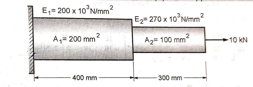
Q.5 A stepped bimetallic bar with circular cross-section is shown in fig, is subjected to an axial pull of 10 kN. Determine:
1) the nodal displacement 2) elements stress and
3) the support reaction
Solution:
Given: l1 = 400 mm
l2 = 300 mm
A1 = 200 mm2
A2 = 100 mm2
E1 = 200 x 103 N/ mm2
E2 = 270 x 103 N/ mm2
P = 10000 N
Fig shows an assemblage of two 1D spar element. Its elemental connectivity is given below
Element Number | Global Node number ‘n’ of | |
Local Node 1 | Local Node 2 | |
1 | 1 | 2 |
2 | 2 | 3 |
2. Element stiffness matrix
For Element 1,

For Element 2,

3. Global stiffness matrix


4. Global load vector

5. Global nodal displacement vector

6. Global stiffness-nodal displacement relationship
Hence after the assembly, the equilibrium equation is,

At node 1, U1 = 0, there is rigid support.
Using elimination approach, first rows and columns are eliminated.
7. Nodal Displacements

Solving two equations for two unknowns, we get,
U2 = 0.1 mm and U3 = 0.211 mm

8. Stresses in elements:
Stresses are given by,

In element 1,

In element 2,

9. Reaction force at support
We have,
104 (10U1 – 10U2 ) = R
104 (10 x 0 – 10 x 0.1) = R
R = -10 x 103 kN
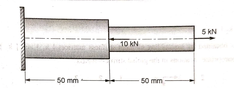
Q.6 Find the stresses in a stepped bimetallic bar, shown in figure, due to forces 10kN and 5kN. Use following data:
l1 = 50 mm A1 = 150 mm2 E1 = 200 x 103 N/ mm2
l2 = 50 mm A2 = 100 mm2 E2 = 70 x 103 N/ mm2
Solution:
Given:
l1 = 50 mm A1 = 150 mm2 E1 = 200 x 103 N/ mm2
l2 = 50 mm A2 = 100 mm2 E2 = 70 x 103 N/ mm2
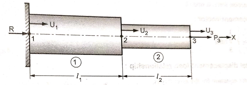
Fig shows an assemblage of two 1D spar element. Its elemental connectivity is given below
Element Number | Global Node number ‘n’ of | |
Local Node 1 | Local Node 2 | |
1 | 1 | 2 |
2 | 2 | 3 |
2. Element stiffness matrix
For Element 1,

For Element 2,

3. Global stiffness matrix


4. Global load vector

5. Global nodal displacement vector

6. Global stiffness-nodal displacement relationship
Hence after the assembly, the equilibrium equation is,

At node 1, U1 = 0, there is rigid support.
Using elimination approach, first rows and columns are eliminated.
7. Nodal Displacements

Solving two equations for two unknowns, we get,
U2 = -8.33 x 10⁻³ mm and U3 = 27.4 x 10⁻³ mm

8. Stresses in elements:
Stresses are given by,

In element 1,

In element 2,

9. Reaction force at support
We have,
104 (60U1 – 60U2 ) = R
104 (60 x 0 – 60 x (-8.33 x 10⁻³)) = R
R = -5 x 10³ kN
Q.7 What is shape Function?
Solution: The values of the field variable computed at the nodes are used to approximate the values at non-nodal points (that is, in the element interior) by interpolation of the nodal values. For the three-node triangle example, the field variable is described by the approximate relation
φ(x, y) = N1(x, y) φ1+ N2(x, y) φ2+ N3(x, y) φ3
where φ1, φ2, andφ3are the values of the field variable at the nodes, and N1, N2, and N3are the interpolation functions, also known as shape functions or blending functions.
In the finite element approach, the nodal values of the field variable are treated as unknown constants that are to be determined. The interpolation functions are most often polynomial forms of the independent variables, derived to satisfy certain required conditions at the nodes.
The interpolation functions are predetermined, known functions of the independent variables; and these functions describe the variation of the field variable within the finite element.
Let  be the natural coordinate of 1D element, then the shape functions are given by


Q. 8 Discuss the general procedure of FEM.
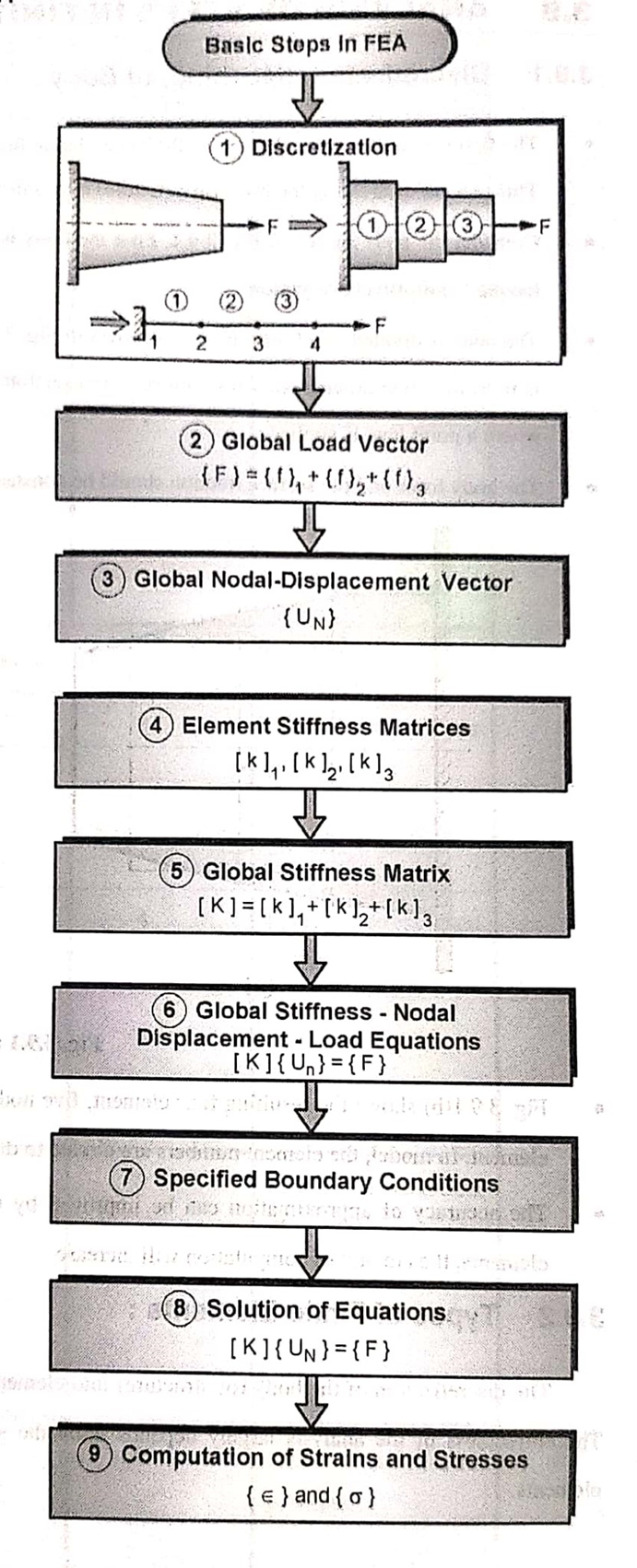
Solution: To summarize in general terms how the finite element method works we list main steps of the finite element solution procedure below.
Q.9 Explain discretization technique.
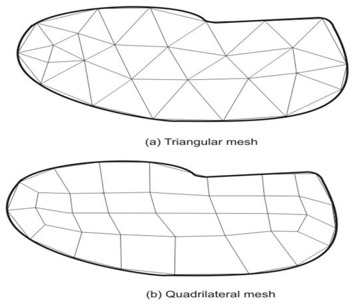
Solution: The need of finite element analysis arises when the structural system in terms of its either geometry, material properties, boundary conditions or loadings is complex in nature. For such case, the whole structure needs to be subdivided into smaller elements. The whole structure is then analyzed by the assemblage of all elements representing the complete structure including its all properties. The subdivision process is an important task in finite element analysis and requires some skill and knowledge. In this procedure, first, the number, shape, size and configuration of elements have to be decided in such a manner that the real structure is simulated as closely as possible. The discretization is to be in such that the results converge to the true solution. However, too fine mesh will lead to extra computational effort. Fig. shows a finite element mesh of a continuum using triangular and quadrilateral elements. The assemblage of triangular elements in this case shows better representation of the continuum. The discretization process also shows that the more accurate representation is possible if the body is further subdivided into some finer mesh.
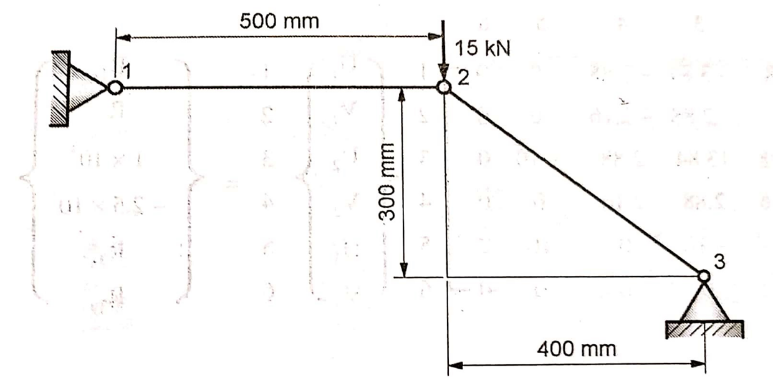
Q.10 The two bar truss is shown in fig. The modulus of elasticity for four bar material is 70 x 103 N/mm2 and cross sectional area of each element is 200 mm2. Determine
1) The element stiffness matrix
2) The global stiffness matrix
3) The nodal displacements
4) The stresses in each elements
5) The reaction forces
Solution
Given: E = 70 x 103 N/mm2 A = 200 mm2
l1 = 500 mm P2y = -15 kN
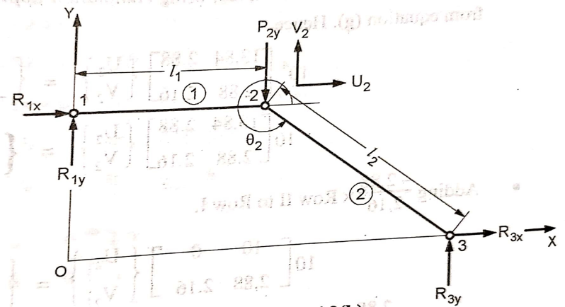
From fig,

Table below shows the element connectivity in the assembly
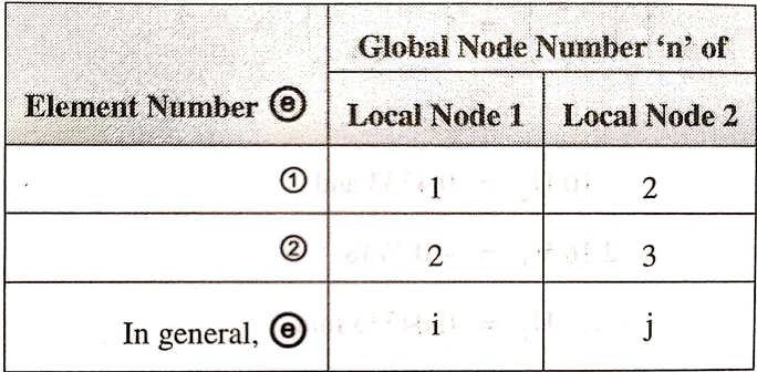
The values for Cx and Cy for all elements are

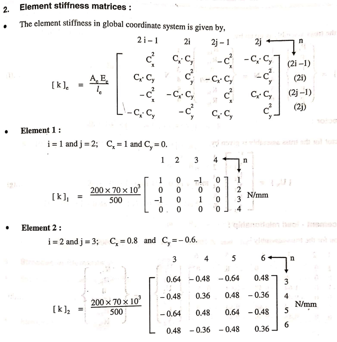
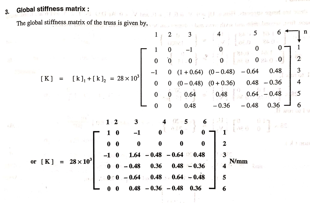
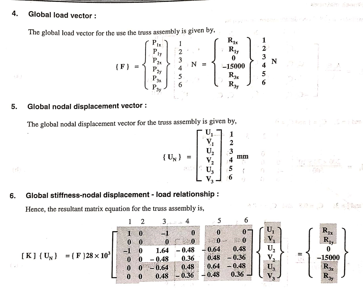
7. Nodal Displacements:

From the above equation, by solving for two unknowns
U2 = -0.7143 mm and V2 = -2.4405 mm
8. Reaction forces at support
28 x 103 [U1 –U2] = R1x
28 x 103 [0 –(-0.7143)] = R1x
R1x = 20000 N
R1y = 0
28 x 103 [-0.64U2 +0.48V2] = R3x
28 x 103 [-0.64 x (-0.7143) +0.48(-2.4405)] = R3x
R3x = -20000 N
28 x 103 [-0.48U2 -0.36V2] = R3y
28 x 103 [-0.48(-0.7143) -0.36(-2.4405)] = R3y
R3y = 15000 N
R1x =20000 N R1y = 0 R3x =-20000 N R3y=15000 N
10. Stresses in Elements

For element 1,

For element 2,
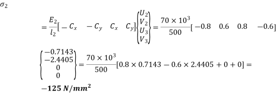
Q.11 Write down in detail, the steps to solve a 1D FEM problem.
Solution:
Step I: Discretization
Discretization is a process of dividing a body into finite number of elements.
Step II:Formulation of Global Load Vector
The elemental force vectors in the global coordinate system for all elements are assembled to form the global load vector {F} for the entire body.
The global Load Vector is given by,

Where F1, F2, F3, …, FN are the loads acting at nodes 1,2,3,…,N respectively
Step III:Formulation of Global Nodal Displacement Vector
The global nodal displacement vector {UN} is formed for the entire body.
The global nodal displacement vector is given as

Where U1, U2, U3, … , UN are the displacements acting at nodes 1,2,3,…,N respectively
Step IV:Formulation of elemental stiffness matrices
After the body is discretized, the elemental stiffness matrix is formulated for all discretized elements.
Consider a one-dimensional rod element as shown in fig.

It has two nodes. Each node has one degree of freedom
Let
l = length of element
A = Cross-sectional area
E = modulus of Elasticity
f1 = Force acting at node 1
f2 = Force acting at node 2
u1 = displacement of node 1
u2 = displacement of node 2
Stiffness of rod element is

From fig,

And 

The above equations in matrix form can be written as

Where,
{f} =  = elemental force vector
[k] = = elemental stiffness matrix
{uN} =  = elemental nodal displacement vector
Step V:Formulation of Global Stiffness Matrix
The global stiffness matrix is formed from the elemental nodal stiffness matrices.
Such as

Step VI:Assembly of Global Stiffness – Nodal Displacement – Load Equations
The relationship between the global stiffness matrix [K], global nodal displacement vector {UN} and global load vector {f} is expressed as
{f} = [K]{UN}
This equation is called as Finite element equation.
If N is the total degree of freedom of the body.
Then dimension of
Step VII:Specify boundary conditions
The specified boundary conditions are incorporated in equilibrium equation by using elimination approach or penalty approach.
Step VIII:Solution of Equations
After including the boundary conditions, the modified equations are solved for the unknown nodal displacements.
Step VIII:Computation of Elemental stresses and strains
Elemental strains are calculated from nodal displacements by

Where,
 = Element strain
 = element strain-nodal displacement matrix
And from the strain calculated, stresses can be calculated as

Where,  = element stress
