Unit 4
Q.1 What is absolute and incremental coordinate system?
A1) In the absolute programming, the end point of a motion is programmed with reference to the program zero point.
In incremental programming, the end point is specified with reference to the current tool position.
Absolute traverse to N1, then to N2
X20.0 Z50.0 X50.0 Z30.0
Absolute traverse to N1, incremental to N2
X20.0 Z50.0 U30.0 W-20.0

Q.2 Explain Zero points or reference points.
A2)
Origin is always located at some position on M/C table (usually at south west corner/Lower left-hand) of the tables & all tool location are defined W.R.T. this zero
2. Workpiece Zero or Fixed Zero (A)
Very common with CNC M/C used now a days. Operator gas lobeity to set zero point at any convenient position on M/C table. Blocking point is the workpiece zero point
3. Program Zero Point (W)
Program zero point is the starting point of workpiece blank
4. Start point (B)
Start point is to be determined in the program
5. Reference point (R)
The reference is to be determined by measuring system. The distsnce between R and M must be known. Normally R is not fixed.
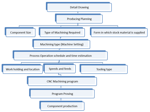
Q.3 What are the steps involved in part programming?
A3)
Q.4 Give the function of following G and M codes.
A4)
G00 Positioning rapid traverse
G01 Linear interpolation (feed)
G02 Circular interpolation CW
G03 Circular interpolation CCW
G04 Dwell
G41 Tool nose radius compensation left
G42 Tool nose radius compensation right
G90 Absolute command
G91 Incremental command
G94 Feed per minute
G95 Feed per revolution
G98 Return to initial point in canned cycle
G99 Return to R point in canned cycle
M01 Optional program stop request
M02 Program end
M03 Spindle ON clock wise (CW)
M06 Tool change
M07 Mist coolant ON (coolant 1 ON)
M09 Coolant OFF
M30 End of program, Reset to start
Q.5 What is tool length compensation?
A5) Different tools of different lengths are used in machining any part. The lengths of the tools are not considered in the part program. They are entered in the machine’s memory, and are considered automatically for each motion in the program depending on the tool that is being used. The tool lengths in the Z direction are called the Tool length offsets.
Codes Function
G43 Make the value of the cutter’s offset add to the value of Z coordinates of the program
G44 Make the value of the cutter’s offset subtract the value of Z coordinates of the Program
G49 Cancel the offset of the length of the cutter
The procedure of mentioning the difference of length of tool assumed during programming and actual tool used for machining is called tool length compensation
1) If the actual tool length is more than the assumed tool, the difference should be mentioned as follows
G43 H01
H01 – here 01 specifies the address where the difference of tool will be mentioned
2) If the actual tool length is less than the assumed tool, the difference should be mentioned as follows
G44 H01
H01 – here 01 specifies the address where the difference of tool will be mentioned.

Q.6 Explain cutter radius compensation.
A6) When the Endmill cutter of some specified diameter is commanded to position at a location, actually the centre point of the cutter only coincide with the addressed point of the work piece.
So, it is necessary to shift the cutter for a radius amount towards left or right from the position. The procedure of shifting the tool of radius amount is called as Cutter Radius Compensation
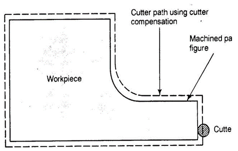
G41 - Cutter radius compensation left
G42 - Cutter radius compensation right
G40 - Cutter radius compensation cancel
The type of compensation is selected from the starting point as follows
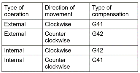
G41 - Cutter radius compensation left
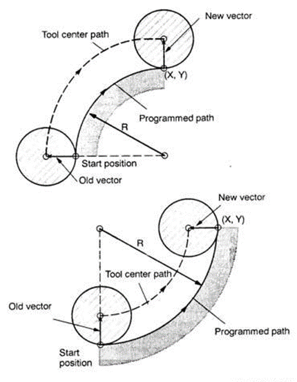
G41 D07;
Here, D specifies the address of offset at which the radius of tool will be mentioned
G42 - Cutter radius compensation right
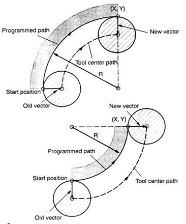
G41 D07;
Here, D specifies the address of offset at which the radius of tool will be mentioned
Q.7 Explain canned cycle for facing and grooving with example.
A7) Canned cycle for facing
G72 cycle is used for facing operation.
Programming syntax:
G72 W… R…
G72 P… Q… U… W… F… S…
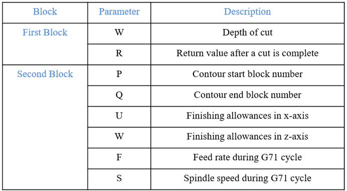
G72 Facing Cycle Example:
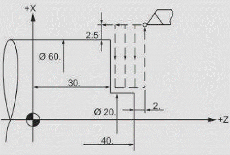
N5 G00 X65 Z42
N6 G72 W2 R2
N7 G72 P8 Q9 U0 W0 F0.3
N8 G00 Z30
N9 G01 X20
Canned Cycle for Grooving
G75 cycle is used for grooving
Programming syntax :
G75 X…
G75 X… Z… P… Q… R…
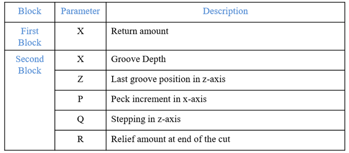
G75 Canned Cycle Grooving CNC Programming Example
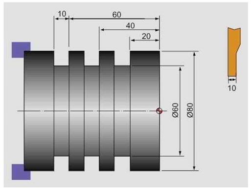
N10 G50 S500 T0100
N20 G97 S400 M03
N30 G00 X90.0 Z1.0 T0101
N40 G00 X82.0 Z-60.0
N50 G75 R1.0
N60 G75 X60.0 Z-20.0 P3000 Q20000 F0.1
N70 G00 X90.0
N80 G00 X200.0 Z200.0 T0100
N90 M30
Q.8 Explain canned cycle for drilling operation.
A8) G81 canned cycle is used for drilling
Programming syntax :
G81 X... Y... Z... R... K... F...

Working Example:
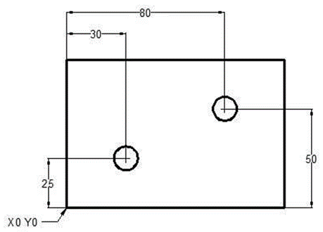
N10 T1 M06
N20 G90 G54 G00 X30 Y25
N30 S1200 M03
N40 G43 H01 Z5 M08
N50 G81 Z-10 R2 F75
N60 X80 Y50
N70 G80 G00 Z100 M09
N80 M30
Q.9 Write NC Part Program for the part as shown in fig. Assume suitable data.
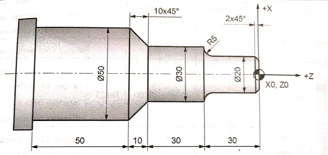
A9) Assumptions:
Spindle speed N = 200 rpm
Feed rate f = 0.25 mm/rev
Program:
O1006
N0 G90
N1 G71
N2 G92 M43 S200
N3 G95
N4 G28 U0 V0
N5 M06 T0101
N6 M03 S200
N7 G00 X60 Z1 M08
N8 G73 X52 Z-120 F0.25 S200 D0.5
N9 G00 X52 Z1
N10 G73 X50 Z-120 F0.25 S200 D0.25
N11 G00 X51 Z1
N12 G73 X32 Z-60 F0.25 S200 D0.5
N13 G00 X33 Z1
N14 G73 X30 Z-60 F0.25 S200 D0.25
N15 G01 X50 Z-70
N16 G01 X51 Z1
N17 G01 X31 Z1
N18 G73 X22 Z-25 F0.25 S200 D0.5
N19 G00 X23 Z1
N20 G73 X20 Z-25 F0.25 S200 D0.25
N21 G03 X30 Y-30 I00 K-5 F0.25
N22 G00 X31 Z1
N23 G00 X16 Z0
N24 G01 X20 Z-2
N25 G00 X21 Z1
N26 G00 X0 Z0
N27 G28 U0 W0
N28 M05
N29 M09
N30 M02
N31 M30
Q.10 Write a part program to machine the component as shown in fig.
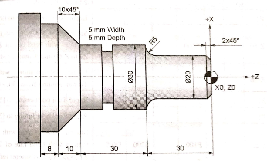
A10) Assumptions:
Spindle speed N = 200 rpm
Feed rate f = 0.25 mm/rev
Program:
O1007
N0 G90
N1 G71
N2 G92 M43 S200
N3 G95
N4 G28 U0 V0
N5 M06 T0101
N6 M03 S200
N7 G00 X60 Z1 M08
N8 G74 X52 Z-78 F100 S200 D0.5
N9 G00 X53 Z1
N10 G74 X50 Z-78 F100 S200 D0.25
N11 G00 X51 Z1
N12 G74 X32 Z-60 F100 S200 D0.5
N13 G100 X51 Z1
N14 G74 X30 Z-60 F100 S200 D0.25
N15 G01 X50 Z-71
N16 G01 X51 Z1
N17 G01 X31 Z1
N18 G74 X22 Z-25 F100 S200 D0.5
N19 G00 X23 Z1
N20 G74 X20 Z-25 F100 S200 D0.25
N21 G03 X30 Y-30 I00 K-5 F100
N22 G00 X31 Z1
N23 G00 X16 Z0
N24 G01 X20 Z1
N25 G00 X21 Z1
N26 M06 T0201
N27 G00 X31 Z-45
N28 G01 X24 Z-45
N29 G00 X31 Z-45
N30 G00 X31 Z1
N31 G00 X0 Z1
N32 G28 U0 W0
N33 M05
N34 M09
N35 M02
N36 M30
Q.11 Write a CNC program to cut a slot for the component shown inn fig, by using a end mill of dia 6mm. The depth of slot is 2mm. Assume suitable data.
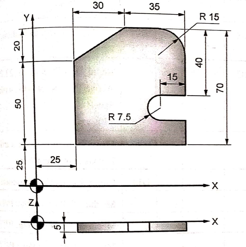
A11) D = 6 mm
Assume:
V = 25 m/min
Fz = 0.1 mm/tooth
Take Z = 3

F = Fz Z N = 0.1 x 3 x 1300 = 390 mm/min or 400 mm/min
Program:
O1008
N0 G17
N01 G71
N02 G40
N03 G80
N04 G28 U0 V0 W0
N05 G91 X0
N06 G00 X0 Y0
N07 G92
N08 M06 T01
N09 G00
N10 G90 X0 Y0
N11 G43 Z0 M08 H01
N12 G00 X22 Y22 M03 S1300
N13 G01 Z-2 F400
N14 G42 X25 D11
N15 G01 X0
N16 Y40
N17 X75
N18 G02 X75 Y55 I00 J7.5
N19 G01 X90
N20 Y80
N21 G03 X75 Y95 I-15 J00
N22 G01 X55
N23 X25 Y75
N24 Y25
N25 G00 Z0
N26 G28 U0 V0 W0
N27 G91 Z0
N28 G28 U0 V0 W0
N29 G91 X0 Y0 M05
N30 G40
N31 G80
N32 G49
N33 M09
N34 M02
N35 M30
Q.12 Write a CNC program for drilling the three holes in part as shown in fig

A12) Drill Dia = D =10 mm
Assume:
V = 60 m/min
Fz = 0.5 mm/tooth
Thickness of plate = 10 mm
Take Z = 1

F = Fz Z N = 0.5 x 1 x 1900 = 954.93 mm/min or 900 mm/min
Program:
O1009
N0 G17
N01 G71
N02 G40
N03 G80
N04 G28 U0 V0 W0
N05 G91 X0
N06 G00 X0 Y0
N07 G92
N08 M06 T01
N09 G00
N10 G90 X0 Y0
N11 G43 Z2 M08 H01
N12 G00 X12 Y55 M03 S1900
N13 G01 Z-10 F950
N14 G00 Z2 M05
N15 G00 X30 Y35 M03 S1900
N16 G01 Z-10 F950
N17 G00 Z2 M05
N18 G00 X60 Y25 M03 S1900
N19 G01 Z-10 F950
N20 G00 Z2 M05
N21 G00 Z0
N22 G28 U0 V0 W0
N23 G91 Z0
N24 G28 U0 V0 W0
N25 G91 X0 Y0 M05
N26 G80
N27 G49
N28 M09
N29 M02
N30 M30