Unit 4
Q.1 What do you meant by balancing. Explain need of balancing.
A1)
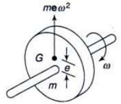
Need of Balancing
Q.2 What is static and dynamic balancing
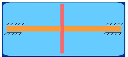
A2) Static Balancing
A system is said to be in static balance if the net dynamic force acting on the system is zero.
Σ F = 0
The net dynamic force acting on a shaft is zero. This requires that the line of action of three centrifugal forces must be same. In other words, the center of line of masses of the system must lie on the axis of the rotation
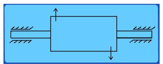
Dynamic Balancing
A system is said to be in dynamic balance if the net dynamic forces as well as net dynamic couples are equal to zero respectively.
Σ F = 0
Σ T = 0
The net dynamic force acting on a shaft is zero. This requires that the line of action of three centrifugal forces must be same. In other words, the center of line of masses of the system must lie on the axis of the rotation.
The net couple due to dynamic forces acting on a shaft is equal to zero. In other words, the algebraic sum of moments about any point on the plane must be zero. i.e. the axis of shaft must coincide with the axis of rotation.
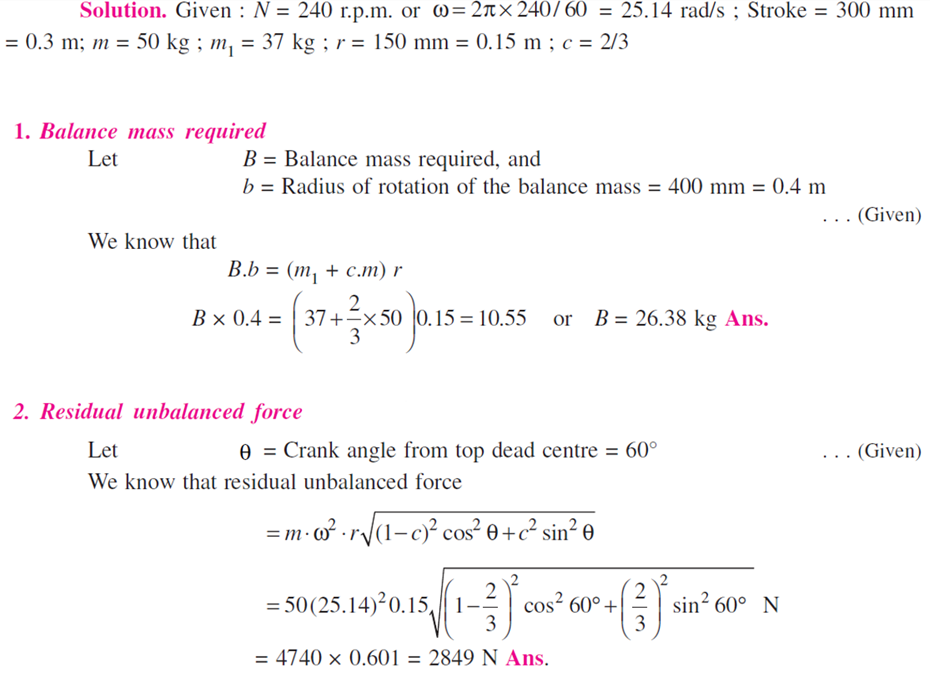
Q.3 A single cylinder reciprocating engine has speed 240 r.p.m., stroke 300 mm, mass of reciprocating parts 50 kg, mass of revolving parts at 150 mm radius is 37 kg. If two-third of the reciprocating parts and all the revolving parts are to be balanced, find: 1. The balance mass required at a radius of 400 mm, and 2. The residual unbalanced force when the crank has rotated 60° from top dead center
Q.4 Four masses m1, m2, m3 and m4 are 200 kg, 300 kg, 240 kg and 260 kg respectively. The corresponding radii of rotation are 0.2 m, 0.15 m, 0.25 and 0.3 m respectively and the angles between successive masses are 45o, 75o and 135o. Find the position and magnitude of balance required, if its radius of rotation is 0.2m. Solve by analytical method.
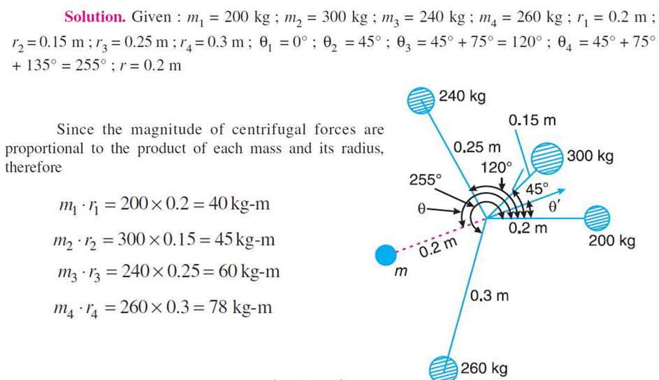
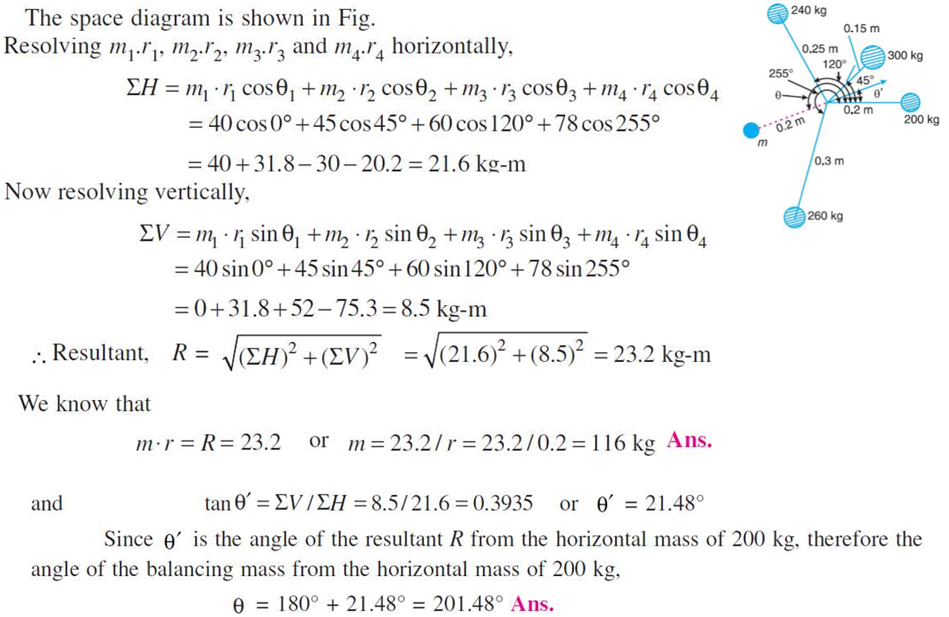
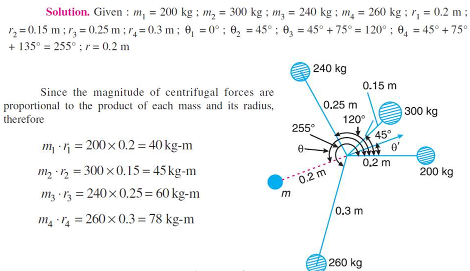
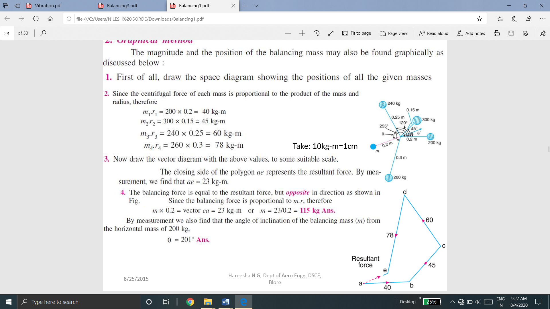
Q.5 Four masses m1, m2, m3 and m4 are 200 kg, 300 kg, 240 kg and 260 kg respectively. The corresponding radii of rotation are 0.2 m, 0.15 m, 0.25 and 0.3 m respectively and the angles between successive masses are 45o, 75o and 135o. Find the position and magnitude of balance required, if its radius of rotation is 0.2m. Solve by graphical method.


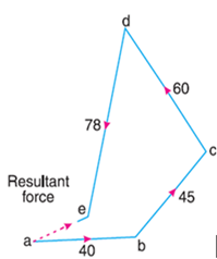
Q.6 Four masses A, B, C and D as shown below are to be completely balanced.
| A | B | C | D |
Mass (kg) | -- | 30 | 50 | 40 |
Radius (mm) | 180 | 240 | 120 | 150 |
The planes containing masses B and C are 300 mm apart. The angle between the planes containing the B and C is 90o. B and C makes angle of 210o and 120o respectively with D in same plane. Find the magnitude and angular position of mass A and the position of planes A and D.
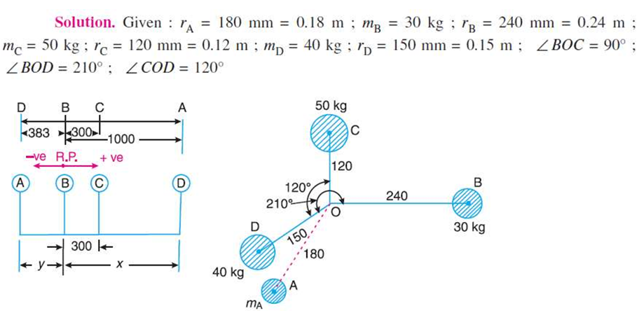
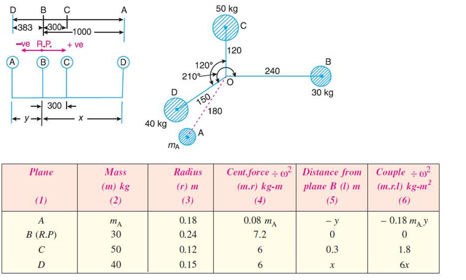
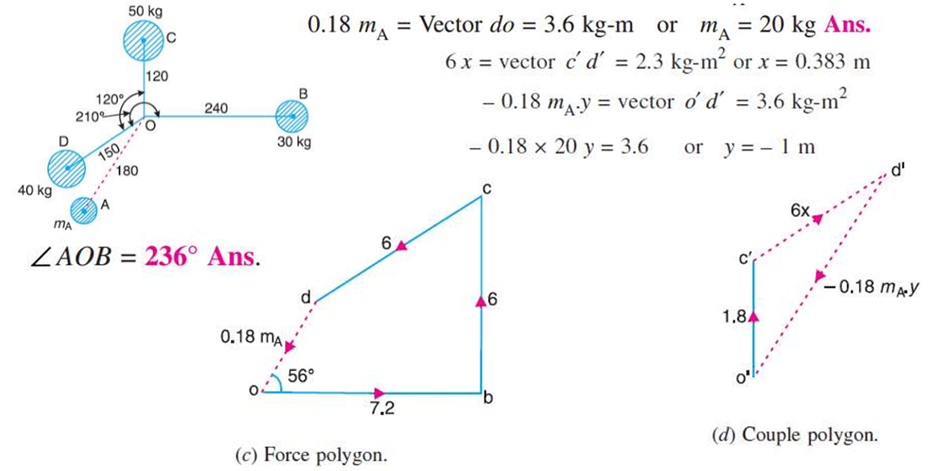
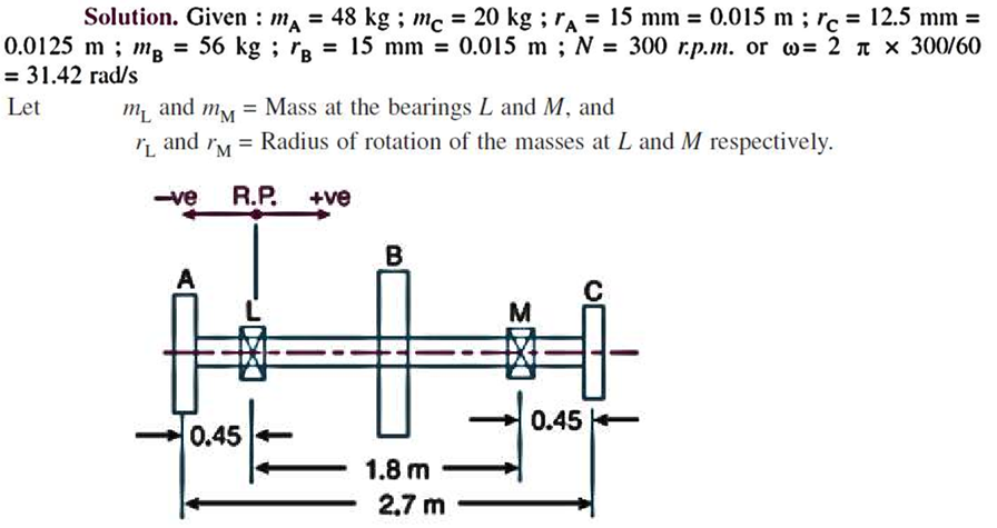
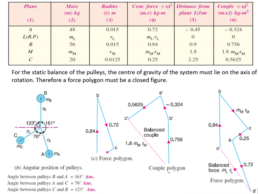
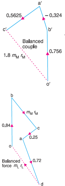
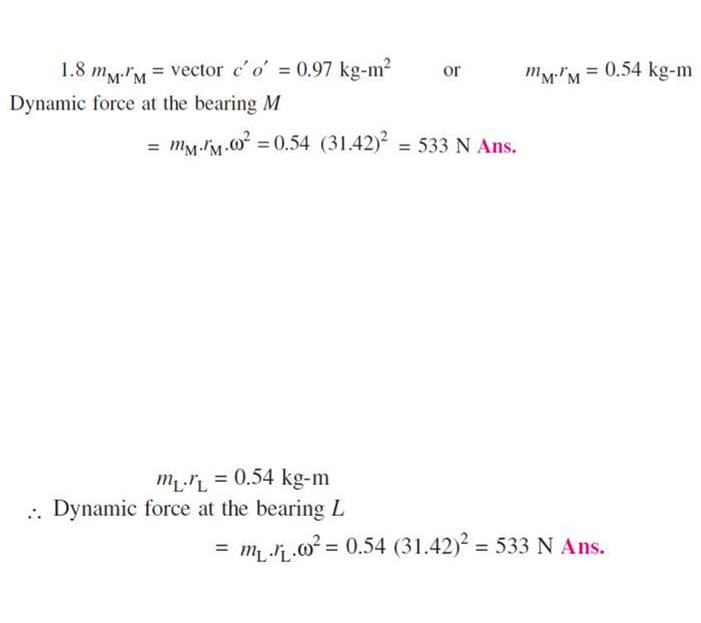
Q.7 A shaft is supported in bearings 1.8 m apart and projects 0.45 m beyond the bearing at each end. The shaft carries three pulleys one at each end and one at middle of its length. The mass of the end pulleys is 48 kg and 20 kg and their center of gravity are 15 mm and 12.5 mm respectively from the shaft axis. The center pulley has a mas of 56 kg and its center of gravity is 15 mm from the shaft axis. If the pulleys are arranged so as to give static balance, determine: 1. Relative angular positions of pulleys, and 2. Dynamic forces produced on the bearings when the shaft rotates at 300 rpm.
Q.8 The firing order in a 6 cylinder vertical 4 stroke in-line engine is 1-4-2-6-3-5. The position stroke is 100 mm and the length of each connecting rod is 200 mm. The pitch distances between the cylinder center lines are 100mm, 100mm, 150mm, 100mm and 100mm respectively. The reciprocating mass per cylinder is 1 kg and the engine runs at 3000 rpm. Determine the out-of-balance primary and secondary forces and couples on the engine, taking a plane midway between cylinder 3 and 4 as a reference plane.
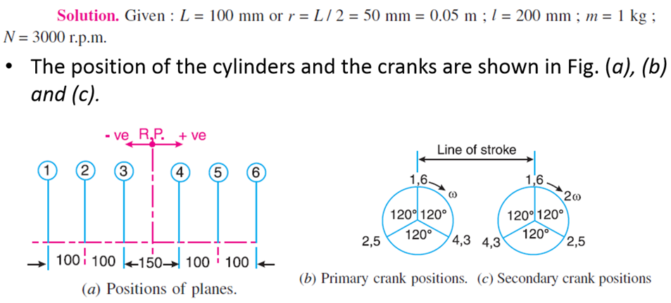
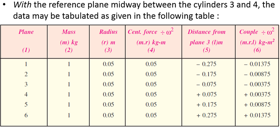
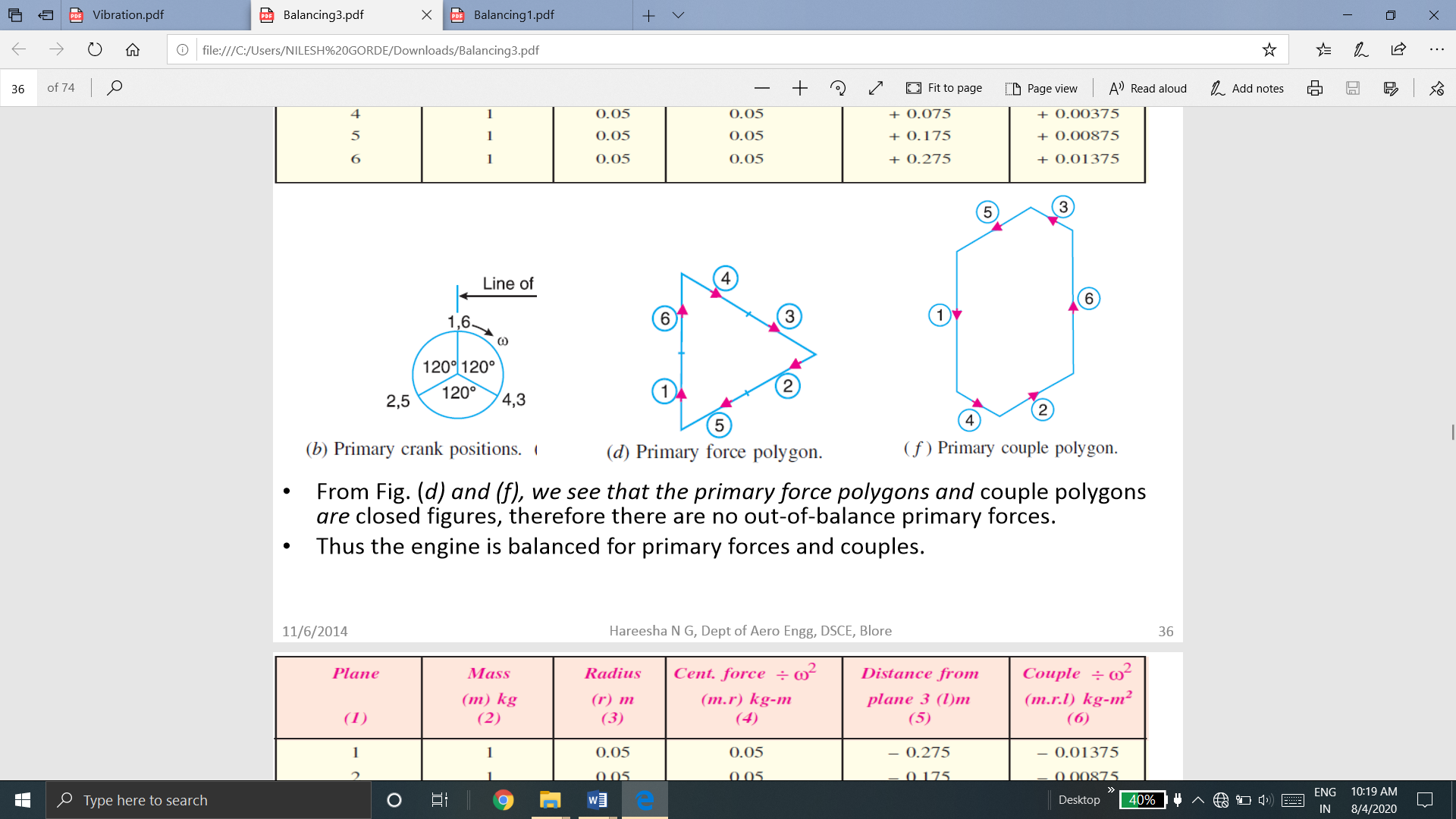
From Fig. (d) and (f), we see that the primary force polygons and couple polygons are closed figures, therefore there are no out-of-balance primary forces. Thus, the engine is balanced for primary forces and couples
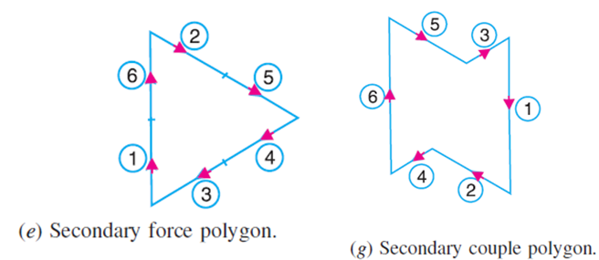
From Fig. (e) and (g), we see that the secondary force polygons and couple polygons are closed figures, therefore there are no out-of-balance secondary forces and couples. Thus, the engine is balanced for secondary forces and couples.
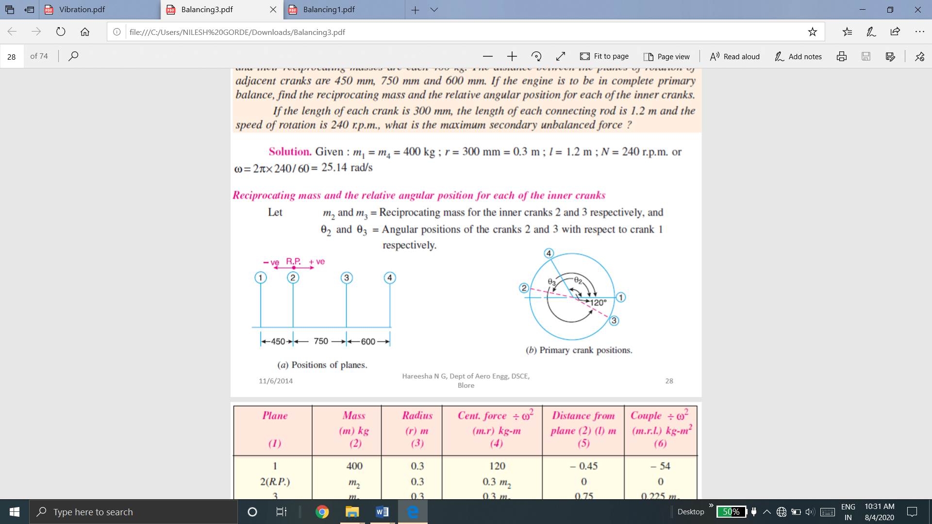
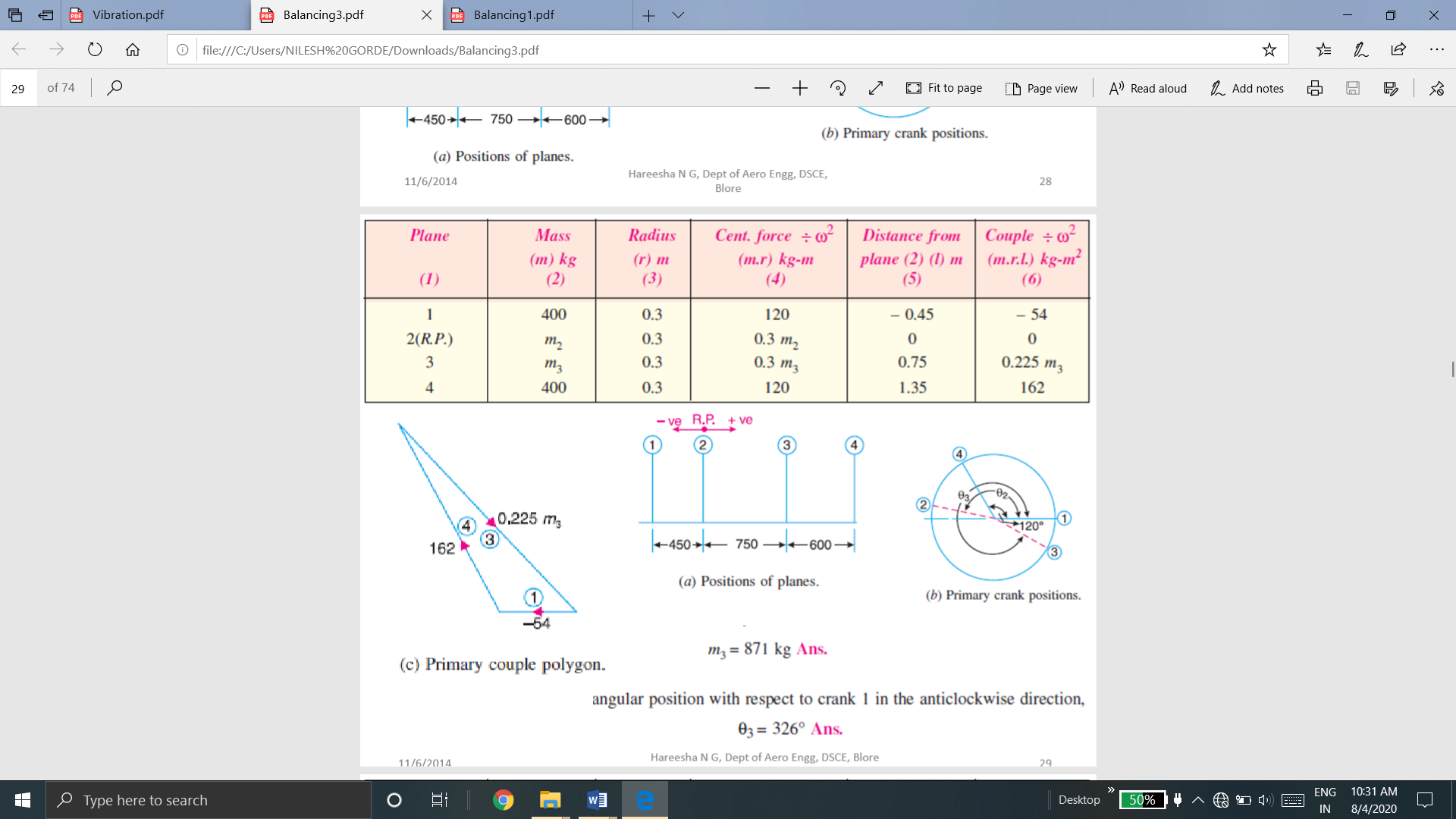
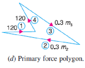
Q.9 A four crank engine has the two outer crank set as 120o to each other, and their reciprocating masses are each 400 kg. The distance between the planes of rotation of adjacent cranks are 450mm, 750 mm and 600 mm. If the engine is to be in complete primary balance, find the reciprocating mass and the relative angular position for each of the inner cranks. If the length of each crank is 300 mm, the length of each connecting rod is 1.2 m and the speed of rotation is 240 rpm, what is the maximum secondary unbalanced force?

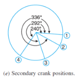
The secondary crank positions obtained by rotating the primary cranks at twice the angle, is shown in Fig (e).
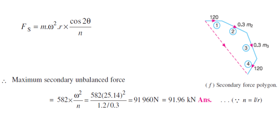
Now draw the secondary force polygon, as shown in Fig. ( f ), to some suitable scale, from the data given in Table (column 4).
The closing side of the polygon shown dotted in Fig. ( f ) represents the maximum secondary unbalanced force.
By measurement, we find that the maximum secondary unbalanced force is proportional to 582 kg-m.
By measurement, the maximum secondary unbalanced force m.r. Cos 2θ= 582 kg-m.
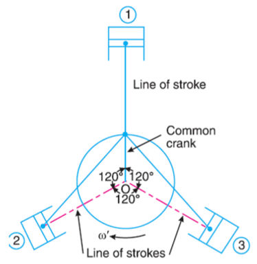
Q.10 The three cylinders of an air compressor have their axes 120o to one another, and their connecting rods are coupled to a single crank. The stroke is 100 mm and the length of each connecting rod is 150 mm. The mass of the reciprocating parts per cylinder is 1.5kg. Find the maximum primary and secondary forces acting on the frame of the compressor when running at 3000 rpm. Describe clearly a method by which such forces may be balanced.

The position of three cylinders is shown in Fig. Let the common crank be along the inner dead centre of cylinder 1. Since common crank rotates clockwise, therefore θ is positive when measured clockwise
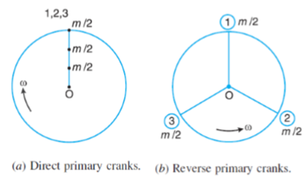
From Fig.(b), we see that the primary reverse cranks form a balanced system. Therefore there is no unbalanced primary force due to the reverse cranks.

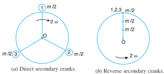
From Fig.(a), we see that the secondary direct cranks form a balanced system.
Therefore there is no unbalanced secondary force due to the direct cranks. From Fig. (b) we see that the resultant secondary force is equivalent to the centrifugal force of a mass 3 m/2 attached at a crank radius of r/4n and rotating at a speed of 2ω rad/s in the opposite direction to the crank.2
