Unit 6
Q.1 What is decibel scale? Give its need.
A1) Need of decibel level
The range of audible sound pressure to which human ear is likely to be subjected is between 2 x 10⁻⁵ N/m2 to 200 N/m2. Because of wide range of sound pressure, it is convenient to describe the sound level through the use of logarithmic scales known as decibel scale. The use of this logarithmic scale helps in covering the entire sound level range by a small scale of numbers rather than the extremely large scale of numbers.
Decibel Scale
Decibel (dB) scale is a log-based scale developed to quantify sound. It compresses range to 0–140 dB
Scale starts at zero when sound pressure equals the threshold of human hearing
It is ten times the logarithm to the base 10 of the ratio of the quantity of sound measured to an arbitrarily chosen reference quantity.

Reference quantity is the threshold of human hearing.
The various parameters used for measurement of sound by using decibel scale are as follows:
Q.2 Derive the expression for relation between sound power level and sound intensity level.
A2) The sound source is assumed to be a point source and its wave to be propagating from it in the form of spherical waves, as shown in fig.
The intensity of sound is given by,


It shows that the intensity of sound in a free space is inversely proportional to the square of the distance from the source of sound.
Now, we have,

We know,
Power = Intensity x surface area
Therefore,


Substituting the above values


Taking  = 1 m2


Where,

Q.3 Explain white noise.
A3) White noise is defined as having the same amplitude at all frequencies (radio static, or a jet of compressed air are pretty good approximations). It is often used as a known input to a system, in order to determine the system’s frequency response.
White noise is a type of noise that is produced by combining sounds of all different frequencies together within the range of human hearing.
In general, if all the tones that a human can hear are taken together and combined, then it gives white noise.
The word ‘white’ comes from optics. White noise is analogous to white light. White light is the light that is made of all monochromatic lights of all colors. Similarly, white noise is the combination of all different frequencies of sound noise.
If one, two, three or few people are talking at the same time, then human brain can pick up one of the few voices and is able to understand it. But if many people, say 1000 people, are talking at the same time, then for a normal human brain it is difficult to pick one voice. Thus many people talking together sounds like a white noise.
Q.4 Explain in detail sound level meter.
A4) Sound Level meter amplifies the very small output signal from microphone and make it available for processing and for visual display by meter contained within the unit.
Block diagram of sound level meter is shown below:
![Industrial Power Transformers -- Operation and maintenance [part 3]](https://glossaread-contain.s3.ap-south-1.amazonaws.com/epub/1643172022_7010121.jpeg)
The electrical signal from the transducer is fed to the pre-amplifier of the sound level meter and, if needed, a weighted filter over a specified range of frequencies. Further amplification prepares the signal either for output to other instruments such as a tape recorder or for rectification and direct reading on the meter.
The rectifier gives the RMS value of the signal. The RMS signal is then exponentially averaged using a time constant of 0.1 s ("FAST") or 1 s ("SLOW") and the result is displayed digitally or on an analog meter.
In some cases, the sound level meter does not include a logarithmic converter. The scale on the indicating device is then exponential so that the linear signal may be read in dB. In this case, the dynamic range of the display is usually restricted to 10 to 16 dB and the precision of the reading is rather poor. In the case of intermittent noise, the user must constantly adjust the amplifier to adapt the output signal to the dynamic range of the display.
When a log converter is used, the display scale is linear in dB and its dynamic range is usually much greater. This type of display has the advantage of providing the same precision at any level and permitting a much better appreciation of the range of fluctuations of the noise to be measured. In this regard, digital displays are less useful.
Q.5 Write a note on sound field
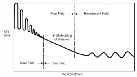
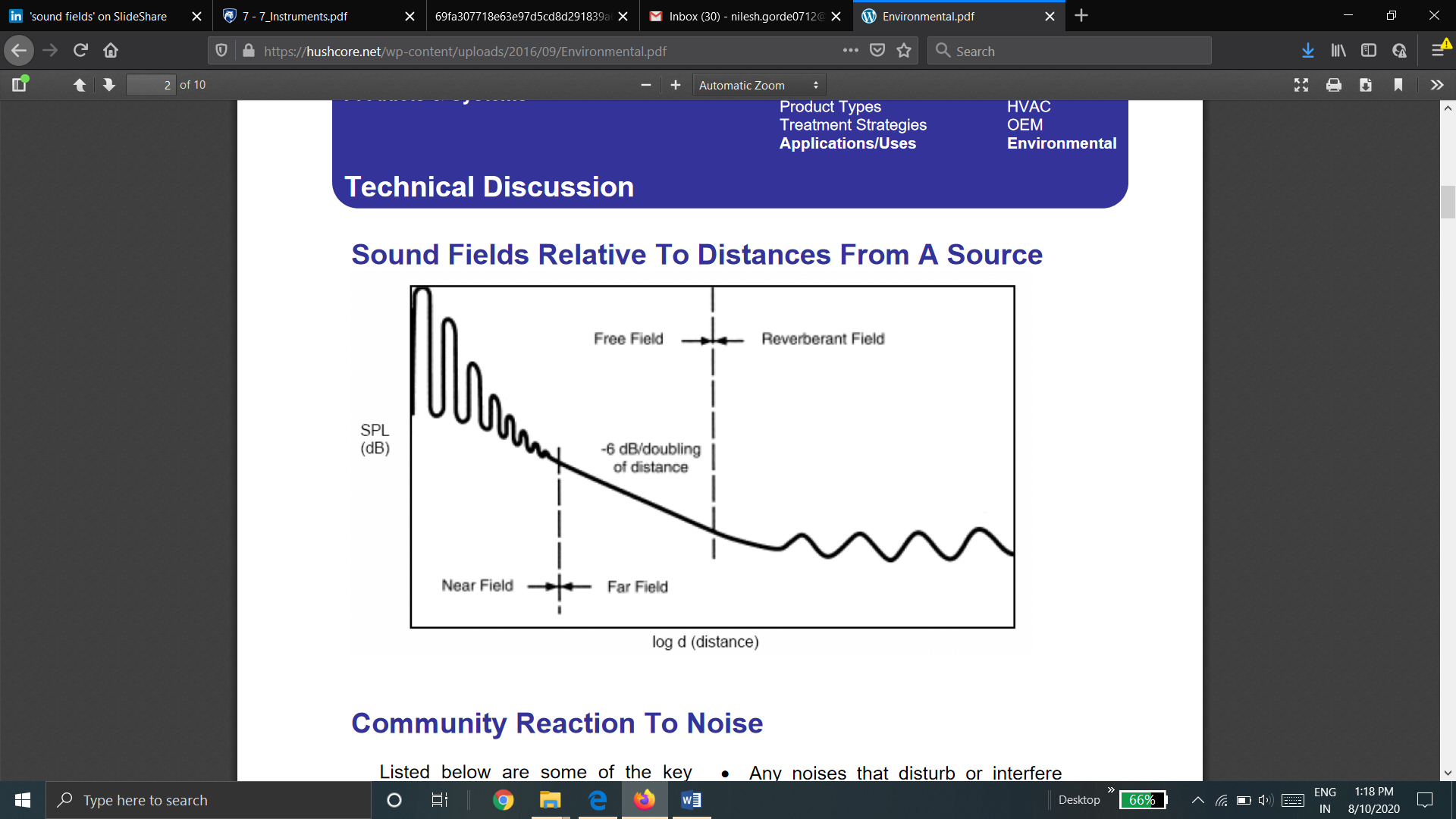
A5) Sound field is the region in a medium in which sound waves are being propagated from the source of sounds.
The various types of sound fields are
The near field is the region close to a sound source usually defined as ¼ of the longest wave-length of the source. Near field noise levels are characterized by drastic fluctuations in levels as much as 10 dBA for small changes in distance from the source. Near field references can pertain to both indoor and outdoor environments.
2. Far Field
The far field describes a sound field beyond the near field limits described above where the sound pressure level (SPL) drops off at the theoretical rate of 6 dB fore very doubling of distance from the source. This rule of thumb is called the Inverse Square Law. Please note that if the far field does not meet the criteria for a free field as described below, then less than the theoretical drop rate will pertain. In such case doubling the distance from the source may yield a drop rate of 3-4 dB.
There are two types of far field, viz
To be considered free field there can be no obstructing surfaces in the sound path of spherical wave propagation. Free field conditions are characterized by SPL loss rates following the Inverse Square Law. Free field references pertain to large open outdoor spaces or in rooms where walls and other surfaces are almost completely absorptive. Anechoic (without echoes) acoustical test chambers simulate free field conditions where omnidirectional sound wave propagation exists
b. Reverberant or diffused field
In a diffuse field there are so many reflections contributing to the total sound field that sound levels measured virtually anywhere in the sound field are the same. Diffuse fields usually pertain to indoor environments. Rooms that are categorized as “live” have larger diffuse fields than free fields. “Dead” rooms have much larger free fields than diffuse field

Q.6 Explain Octave Band
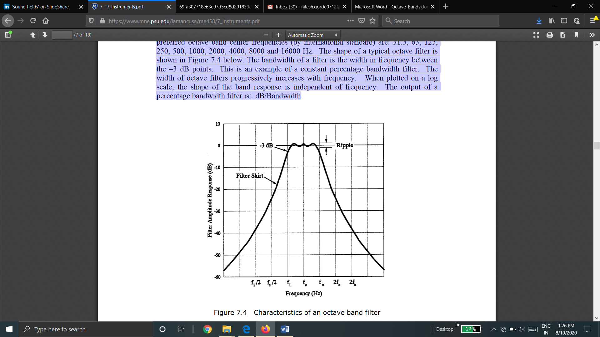
A6) Octave Band - Measures the total acoustical energy within the passband of a band pass filter. The term “octave” denotes a doubling in frequency. Hence, each octave band covers a frequency range of one octave. We refer to the octave band by its center frequency. The center frequencies of successive filters are separated by one octave. The preferred octave band center frequencies (by international standard) are: 31.5, 63, 125, 250, 500, 1000, 2000, 4000, 8000 and 16000 Hz. The shape of a typical octave filter is shown in Figure 7.4 below. The bandwidth of a filter is the width in frequency between the –3 dB points. This is an example of a constant percentage bandwidth filter. The width of octave filters progressively increases with frequency. When plotted on a log scale, the shape of the band response is independent of frequency. The output of a percentage bandwidth filter is: dB/Bandwidth

Characteristic of Octave Band
In general, octave band is defined as the range of frequencies in which the highest frequency is twice the lowest frequency.
If fh is the highest frequency and fl is the lowest frequency, then
fh = 2 fl
and central frequency is given by,
fc =  fl = fh /
If fh and fl is separated by n octave band then,
fh = 2n fl
Q.7 Explain concept of sound reflection, absorption and transmission. Give their coefficients.
A7) When a sound wave strikes one of the surfaces of a room, some of the sound energy is reflected back into the room and some penetrates the surface. Parts of the sound wave energy are absorbed by conversion to heat energy in the material, while the rest is transmitted through.
Similar to a light wave, when a sound wave encounters an object, one of three things can happen:
Usually a combination of all three processes occurs, with the proportion of each depending on the composition of the object and the frequency of the sound wave.

Reflection, Absorption and Transmission can be measured by certain coefficients as below
Reflection Coefficient is defined as the ratio of the sound intensity that is reflected from the boundary material to the intensity of sound incident on it.
It is given as

2. Absorption Coefficient
Absorption Coefficient is defined as the ratio of the sound intensity that is absorbed from the boundary material to the intensity of sound incident on it.
It is given as

3. Transmission Coefficient
Transmission Coefficient is defined as the ratio of the sound intensity that is transmitted from the boundary material to the intensity of sound incident on it.
It is given as

Q.8 Explain noise control at source
A8) Noise control at source
Source of noise may be a machine or mechanical devices, vibrating surface, mechanical shock, mechanical friction, fluid flow, frame burst or an explosion.
It is more economical and efficient to control the noise at the source. Modification at the source of sound are usually considered as the best solution for an industrial noise control problem.
Steps in noise control at source are:
Balancing of unbalanced equipment; Lubrication of moving parts; Tensioning driven belt; Replacement of worn out parts.
Hot working rather than cold working; Using welding rather than stoppers; Using cutting fluid in machining processes.
Use of electric equipment instead of pneumatic equipment; Using stepped dies instead of single-operation dies; Using rotating shears instead of square shears; using press instead of hammers.
Replacing gear drives with belt drives; Using centrifugal instead of propeller fans; Use of proper dampers for vibrating machines; Using properly shaped and sharpen cutting tools.
Replacing metal gears with plastic gears; Replacing solid wheels with pneumatic tyres; replacement of steel sprockets with polyamide plastic sprockets.
By changing manufacturing methods, such as moulding holes in concrete rather than cutting after production of concrete component or keeping noisy operations in same area and separated from non-noisy operations.
An effective noise control procedure is to enclose the sound source in an acoustic enclosure.
Q.9 Explain Anechoic and reverberant chamber.
Anechoic chamber is the special chamber or the room in which all the walls, floor and ceiling are covered by sound absorbing materials for maximum absorption of sound.
The ideal anechoic chamber will have no reflecting surfaces and 100 % sound waves will be absorbed by the acoustic materials.
The anechoic chamber is used to obtain the information like sound radiation pattern and narrow band frequency data.
2. Reverberant Chamber
All the walls, floor and ceiling of the room are covered with hard reflected surfaces in reverberant chamber. There is reflection and re-reflection of sound waves in the room which results in diffuse pressure field.
The ideal reverberant chamber has no absorptivity, means no sound wave is absorbed by any material. All the covered materials are pure reflective.
Reverberant chambers are used to average of energy radiated from different machines. In reverberant chamber, the effort of sound sources is averaged out and hence no information is obtained of phase relationship, directionality and location of sound sources.
To increase the diffusion of sound, the reverberant rooms are usually made of irregular shapes.
For sound power measurement, the reverberant chamber volume should be 200 m3 minimum.
Q.10 Determine different levels
i. Sound pressure level, if rms sound pressure is 1 Pa.
ii. Sound Intensity level, if sound intensity is 1 W/m2 and
iii. Sound Power level of a source generating 1 W of sound Power.
A10) i)  = 1 N/m2
  = 2 x 10⁻⁵ N/m2


ii) I = 1 W/m2  = 10-12 W/m2


iii) W = 1W  = 10-12 W


Q.11 If four machine produces 100 dB, 91 dB, 90 dB and 89 dB. What is the total sound pressure level?
A11)


Therefore, total sound pressure level is 101.16 dB