Unit 1: Simple Stresses and Strains
Q1) Explain general classification of Stresses in a beam.
A1) The generalized classification of stresses is as follows:

Stress induced due to forces which are acting normal to the cross-sectional area of the section or beam is called Normal stress.
Normal Stresses are further classified as Tensile and Compressive Stresses.

When two equal and opposite parallel forces which are not in the same line, act on two parts of the body, then these parts tend to slide over or shear from each other across any section and the stress developed during this process is termed as Shear Stress. Thus these stresses are produced when the forces act tangentially to the cross-sectional area.
This is a type of indirect stress produced due to twisting moment applied to circular cross-section about its axis.
Bending stresses are the stresses that are induced normally at a particular point in the body which is subjected to loads that causes the body to bend. When the loads are applied perpendicular to the axis of the beam, bending moment is induced in the beam.
Q2) Define the following terms:
A2)
When a particular bar is loaded in Tension, the axial elongation is accompanied with lateral contraction (i.e. contraction normal to the direction of applied load). The lateral strain at any point in a bar is proportional to the axial strain at that same point if the material is linearly elastic. The ratio of these strains is a property of the material known as Poisson’s ratio. This dimensionless ratio, usually denoted by the Greek letter ν (nu), can be expressed by the equation

Here negative sign indicates opposite directions or signs for strains. ν is assumed same in Tension as well as Compression. Some values of ν are 0.1 for concrete, 0.5 for rubber and approx. 0 for cork.

It should be noted that Hooke’s law holds good for tensile as well as compressive loads. E given here is known as Modulus of Elasticity or Young’s Modulus.
We know that by using Hooke’s law i.e.
Stress  Strain

This constant of proportionality (E) is known as Modulus of Elasticity or Young’s Modulus. Numerically, Modulus of Elasticity is that value of tensile stress, which when applied to uniform bar will increase its length by unit value of strain. As the strain is dimensionless, the units of Young’s Modulus are same as that of Stress, i.e. Pascal (Pa) or N/m2. This Young’s Modulus is also the slope of stress-strain curve in elastic region that will be discussed later.
Some of the values of E are, Steel = 200-220 GPa, Wrought Iron = 190-200 GPa, Aluminium = 60-80 GPa.


Where C = Constant of proportionality known as Modulus of Rigidity or shear modulus.

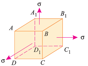
Consider a cube ABCDA1B1C1D1 as shown in fig. Let the cube be subjected to three mutually perpendicular stresses of same intensity.
Here,  = Tensile stresses
 = length of cube
E = Young’s modulus of the cube material.
Now, we will consider deformation of any one particular side (say AB). Here, this deformation will be caused by,
The tensile stress mentioned above will result in longitudinal strain of  /E. The compressive stresses will result in lateral strain of [ν*(
 /E)], where ν = Poisson’s ratio.
Thus, the total strain produced is given as,


Now, the volume of cube is  3, thus
 3
3
Differentiating with respect to  , we get,


Now, replacing the value of  mentioned above.


Now, replacing  3 by
3 by  ,
,

Replacing  by
by  , we get,


The above equation gives relation between Young’s Modulus (E), and Bulk Modulus (K).
Q3) Explain Stress-Strain curve for Ductile materials, with proportional limit, elastic limit, yield point and ultimate stress.
A3) A material is said to be ductile in nature, if it elongates appreciably before fracture. One such material is mild steel. The tensile test of mild steel is carried out on a specimen of uniform cross-section throughout its gauge length. The specimen is gripped between two grips (JAWS) of the tensile testing machine, with which gradually increasing load is applied. The load and extension in the gauge length (50 mm) of the specimen are observed. A graph is drawn between load and extension i.e., stress and strain as shown in fig.
1. Proportional Limit. From the origin O to the point A, stress-strain diagram is a straight line i.e., stress is proportional to strain. Hook’s law holds good up to this point A. Beyond point A, the stress is no longer proportional to the strain. Hence point A is the proportional limit stage. Thus, the limit up to which stress is directly proportional to strain is called proportional limit.
2. Elastic Limit. Point B indicates the elastic limit stage. Between points A and B although the strain increases slightly more than the stress, yet the material is elastic i.e., on the removal of load, the material will regain its original shape and size. If the material is stressed beyond point B, the deformation will take place. Points C and D are upper and lower yield points respectively. Between points B and C, the strain increases more rapidly than the stress. At this point C the dial, which gives the reading of the load suddenly becomes stationary for few seconds to point D. Beyond point D, the load again starts increasing but the elongation increases at faster rate than load up to point E. Hence E indicates maximum or ultimate stress point. The bar of specimen begins to form a local neck. Point F is the breaking point. The extension remains continuous even with lesser load and fracture occurs at point F. The stress corresponding to the peak load is called ultimate tensile stress or ultimate tensile strength or tensile strength. The stress corresponding to the load when the specimen ruptures is called rupture strength.
3. Yield Point. The yield point is the point at which considerable elongation of the test specimen occurs with no noticeable increase in the tensile load (Stress). This phenomenon is known as yielding of the material and point C is called the yield point. The corresponding stress is known as the yield stress. In this region (i.e., between points C and D) the material becomes perfectly plastic, which means that it deforms without an increase in the applied load. The elongation of specimen in the perfectly plastic region is typically 10 to 15 times the elongation that occurs up to the proportional limit.
4. Ultimate Stress. The ratio of maximum load to the original cross-sectional area of a bar is called ultimate stress.

Q4) Explain what are temperature Stresses in Plain Members.
A4) When the temperature of a body is raised or lowered, there is corresponding increase or decrease in its dimensions and if this change in dimensions due to the temperature variation is prevented by application of external forces, the body develops stress in it, which is called the temperature stress ; and the corresponding strain is called the temperature strain. The extension due to rise of temperature, can be checked or suppressed by compressive forces; thereby producing compressive stresses in the body or vice versa. Suppose, a bar of uniform section and of length l is heated through temperature T. The length of the bar will increases depending upon its co-efficient of linear expansion which is defined as the increase in length per unit rise of temperature per unit original length and is generally denoted by the Greek letter  (alpha).
Extension of the bar when free to expand = αTl.
Now suppose, this extension due to increase of temperature is prevented by either fixing the bar at its ends or by the application of external compressive forces.


Which is compressive in nature.
Temperature stress = Temperature strain × E = αTE (compressive)
Conversely, the contraction caused by lowering of the temperature can be checked by applying tensile forces to the bar resulting in temperature stress of tensile nature in it.
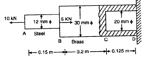
Q5) The diameters of the brass and steel segments of the axially loaded bar
shown in figure are 30 mm and 12 mm respectively. The diameter of the
hollow section of the brass segment is 20 mm.
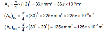
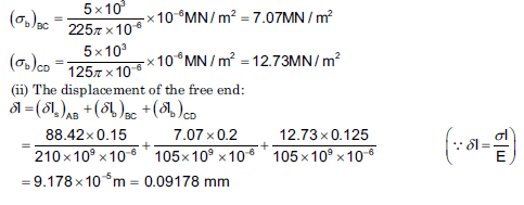
Determine: (i) The maximum normal stress in the steel and brass (ii) The displacement of the free end; Take Es = 210 GN/m2 and Eb = 105 GN/m2
A5)


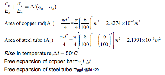
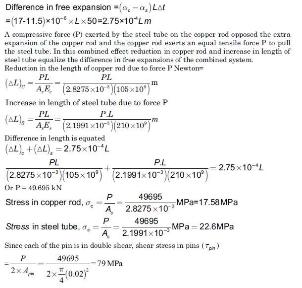
Q7) A Copper rod 6 cm in diameter is placed within a steel tube, 8 cm external diameter and 6 cm internal diameter, of exactly the same length. The two pieces are rigidly fixed together by two transverse pins 20 mm in diameter, one at each end passing through both rod and the tube. Calculate the stresses induced in the copper rod, steel tube and the pins if the temperature of the combination is raised by 50oC. [Take ES=210 GPa, αs =0.0000115 /oC; Ec=105 GPa, αc = 0.000017 /oC]
A7)

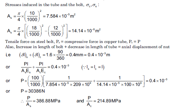
Q8) The steel bolt shown in Figure has a thread pitch of 1.6 mm. If the nut is initially tightened up by hand so as to cause no stress in the copper spacing tube, calculate the stresses induced in the tube and in the bolt if a spanner is then used to turn the nut through 90°.Take Ec and Es as 100 GPa and 209 GPa respectively.
A8)

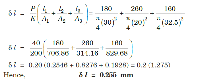
Q9) Find the stresses in three parts and total extension of the bar under an axial pull of 40 kN. Take E = 2 × 10⁵ N/mm2.
A9)

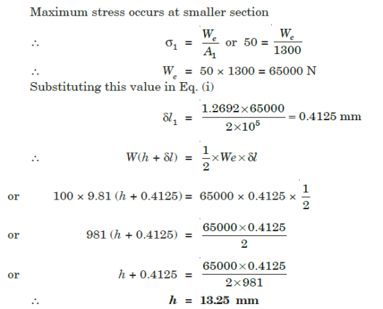
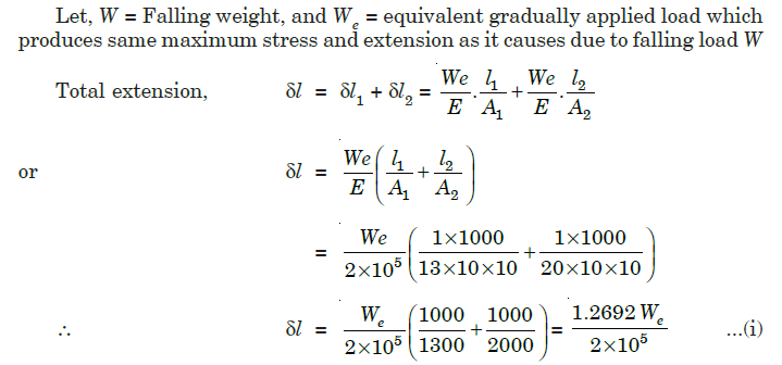
10) A vertical rod 2 m long, fixed at the upper end, is 13 cm2 in area for 1 m and 20 cm2 in area for another 1 m. A collar is attached to the free end. Through what height can a load of 100 kg fall on to the collar to cause a maximum stress of 50 N/mm2?
A10)

