Unit 2: Shear Force and Bending Moment Diagram
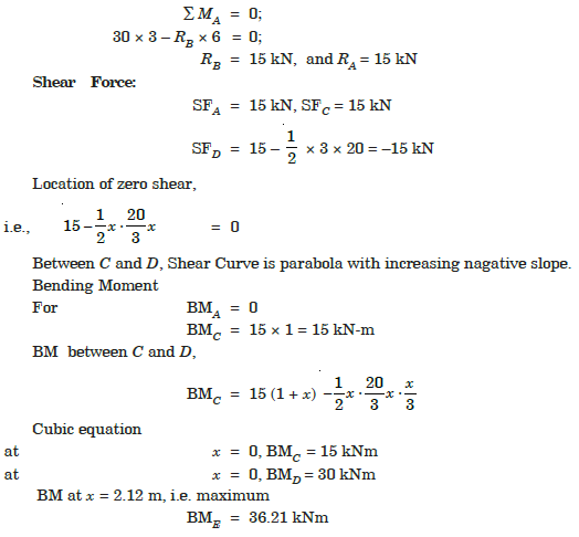
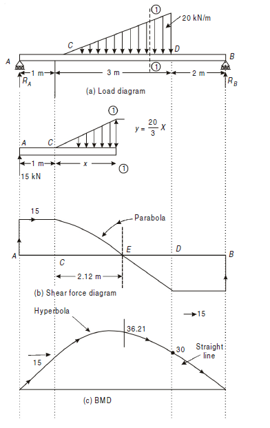
Q1) Explain the concept of Zero Shear Force/Maximum Bending Moment.
A1) We know that,
F=dM/dx
i.e. Shear force may be said to be the rate of change in the bending moment.
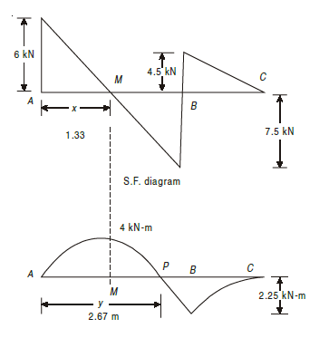
Thus, if at a point dM/dx = 0, i.e. shear force value is zero according to the above equation, it will be called point of zero shear force. Also, if dM/dx=0, then the value of M will be maximum, thus called as maximum bending moment. This mostly takes place when the shear force diagram moves from positive to negative or vice versa. Thus, it crosses the base line at a point where it becomes zero, and at that point in bending moment diagram we achieve maximum value.
Q2) Explain the concept of Point of Contraflexure.
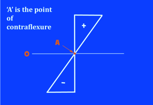
A2) In a beam that's flexing (or bending), the purpose where there's zero bending moment is named as the point of contraflexure. At that time, the direction of bending changes its sign from positive to negative or from negative to positive.
For this alteration to happen, it must undergo zero – the point of contraflexure. On Bending moment diagram, it is at the point where the value of bending moment is momentarily zero.
It can also be explained using an example of moving automobile. If it is going forward at 20m/s and if it needs to go reverse, it will need to momentarily stop and then go reverse, similarly when the value of bending moment becomes zero, is point of contraflexure.
When we consider a member under load, the point of zero bending moment would appear to suggest no reinforcement would be required. However, omitting reinforcement at that point is taken into account inadvisable as, in real life, it may be difficult to locate point of contraflexure, with high accuracy.
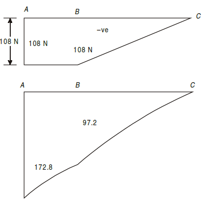
Q3) Draw S.F. and B.M. diagram for the cantilever beam shown in Fig. below.

A3)

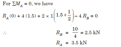
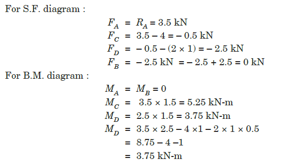
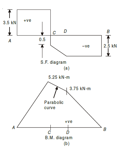
Q4) A simply supported beam of 4 m span is carrying loads as shown in Fig. below. Draw S.F. and B.M. diagrams for the beam.
A4)

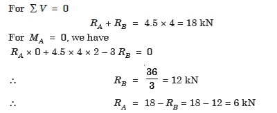
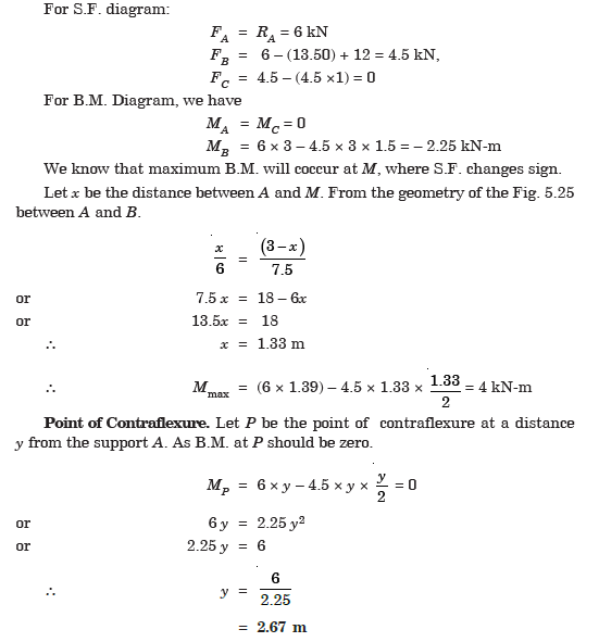
A5) An overhanging beam ABC is shown in Fig. below. Draw the shear force and bending moment diagrams and find the point of contraflexure.
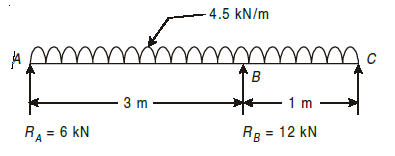
A5)
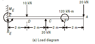
Q6) Draw B.M. and S.F. diagrams for the beam shown in Fig. below, indicating the values at all salient points.
A6)
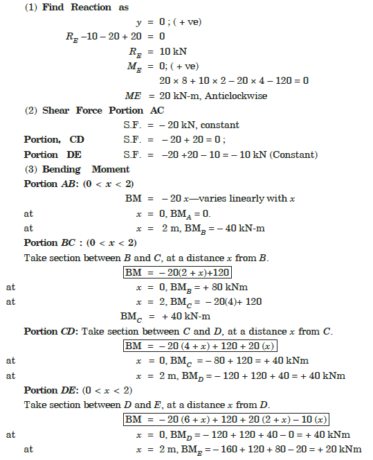
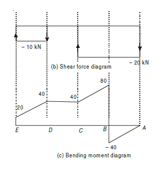
Q7) Construct the bending moment and shearing force diagrams for the beam shown in the figure.
A7)
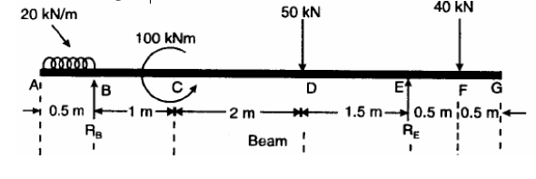
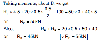
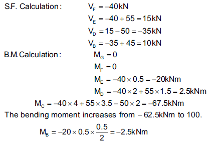
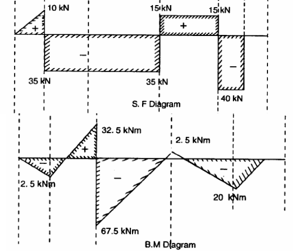
Q8) Calculate the reactions at A and D for the beam shown in figure. Construct the bending moment and shearing force diagrams for the beam shown in the figure.
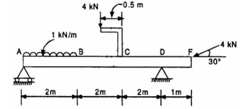
A8)
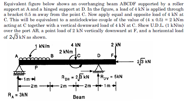
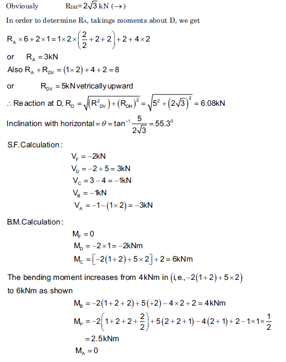
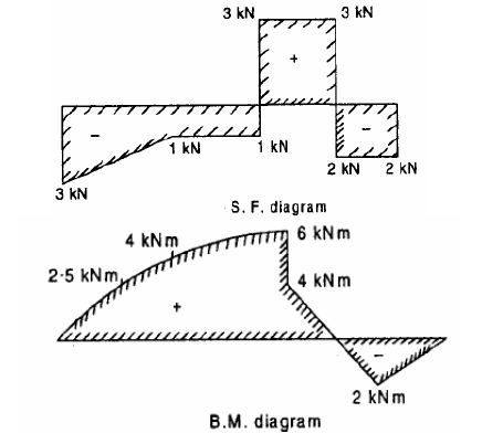
Q9) Construct the bending moment and shearing force diagrams for the beam shown in the figure.
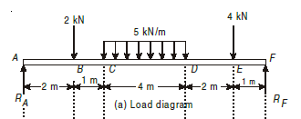
A9)
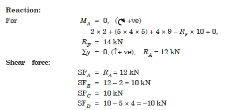
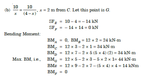
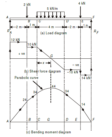
Q10) Construct the bending moment and shearing force diagrams for the beam shown in the figure.
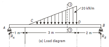
A10)
