Unit 3: Stresses, Slope & Deflection on Beams
Q1) What is the theory of Simple Bending?
A1) Consider small length dx of a simply supported beam subjected to a bending moment M. Now, let us consider any two section viz. AB and CD that will be perpendicular to the axis of beam RS. Due to action of bending moment, the beam as a whole will bend as shown in Fig.(b).
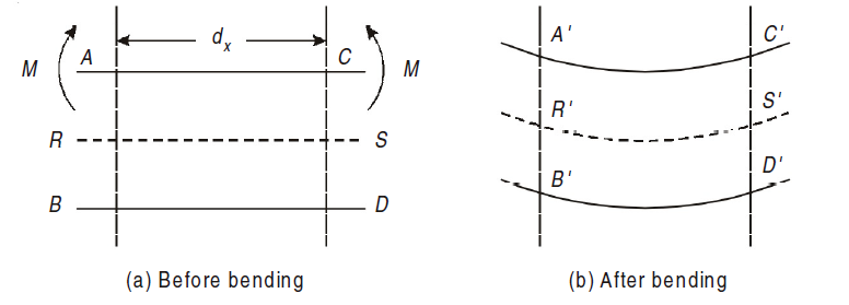
As seen in fig, the top layer ‘AC’ has gone into compression and decreased to A´C´. Layer RS has suffered no change in length, though bent to R´S´. Lower most layer BD has been stretched to B´ D´. Hence layers above RS have been compressed and those below RS have been stretched. This layer RS, neither goes into tension nor compression is also called as Neutral plane or Neutral layer.
The above-mentioned theory is also known as “Theory of Simple Bending”.
We know that on one side of the neutral axis there are tensile type of stresses while on the other, there are compressive type of stresses. Couple is formed by these types of stresses, whose moment should be equal to external moment created(M). The moment of this type of couple, which opposes the external bending moment, is known as the moment of resistance.
Now, let’s consider a section or part of the beam shown in below. Let the neutral axis of the section denoted by NA. Now consider a small layer PQ of the beam section at a distance y from the neutral axis as shown in Fig. below.
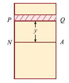
Let δ A = Area of the layer PQ.


Thus, the total stress is given by,

Moment of this total stress about neutral axis is given by,


Here the algebraic sum of all the moments present about the neutral axis should be equal to M. Therefore


The expression  represents the moment of inertia of area of the complete section about the neutral axis. Therefore,

Where I= moment of inertia,
We know that,

Therefore,

The above equation is also known as Bernoulli-Euler bending equation or Flexural Formula.
2. Derive the differential equation for bending.
Consider a small portion PQ of a beam, bent into an arc (As shown in Fig.)

Let,
ds = Length of beam PQ
R = Radius of the arc, into which the beam has been bent
C = Centre of the arc
ds = Length of the beam PQ
R = Radius of the arc, into which the beam has been bent.
ψ = Angle, which the tangent at P makes with x – x axis, and
ψ + dψ = Angle which the tangent at θ makes with x – x axis
From the geometry of figure, we get,
∠PCQ = dψ
ds = R *dψ
considering ds = dx

We know that if x and y be the co-ordinates of point P, then

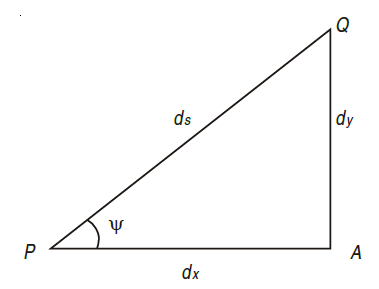
As  is small, tan
 =
=
Differentiating, we get,

We know that,


Substituting the value of (1/R), we get,

i.e.
The above-mentioned equation is known as Differential equation for bending, which also gives the relation between slope, deflection and radius of curvature.
Q2) Explain in steps the procedure of solving slope and deflection numerical using Macaulay’s Method.
A3) The Macaulay’s method is explained as following.
1. This method is similar to double integration method.
2. It is used to find the slope and deflection at any point on the beam.
3. In this method, bending moment at any section is expressed in systematic order.
4. The section x is to be taken in the last portion of the beam.
5. In this method, bending moment of each force or U.D.L. is separated by a compartment of lines.
6. Integrating bending moment equation, we will get slope equation.
7. Again integrating slope equation, we will get deflection equation.
For example, consider a beam subjected to loading as shown in Fig. below.
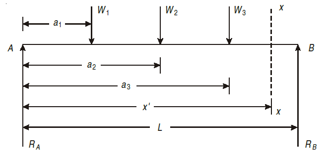
Step I. Determine the support reactions.
Step II. Consider a section x – x at a distance x covering all the loads from left end of the beam.
Step III. Take moment of all forces about section x – x, considering sagging B.M. as positive and hogging as negative.

Step IV. Use differential equation of deflection
i.e.

Step V. Integrating above equation, we get;

Step VI. Again, integrating above equation, we get

Step VII. The constant of integration c1 and c2 are calculated by applying boundary conditions.
Step VIII. Substituting the value of constant, in equation obtained in step V gives general equation for slope and equation in step VI gives general equation for deflection.
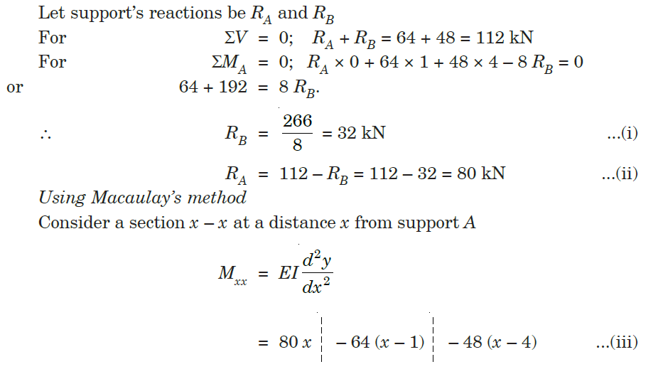
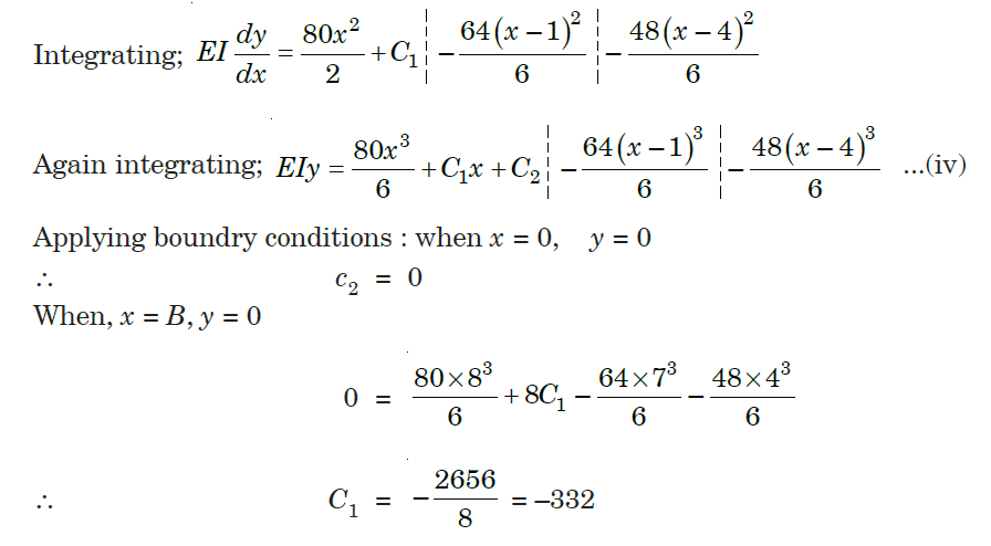
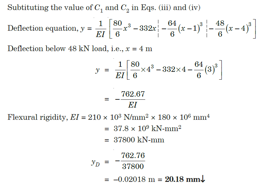
Q3) A simply supported beam of length 8 m carries two concentrated loads of 64 kN and 48 kN magnitude in downward direction at distances of 1 m and 4 m from left end. Find the deflection below the 48 kN load. Take E = 210 GPa and I = 180 × 106 mm4.

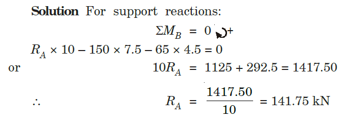
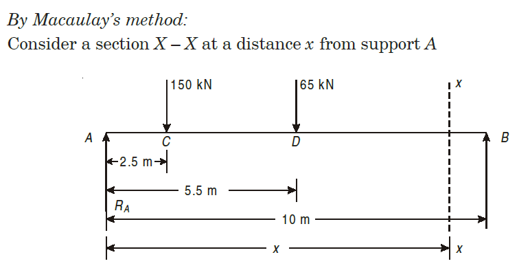
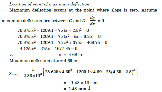
Q4) A beam of uniform section, 10 m long is simply supported at the ends. It carries point loads of 150 kN and 65 kN at distances of 2.5 m and 5.5 m respectively from the left end. Calculate.
(i) Deflection under each load, (ii) Maximum deflection

A3)

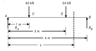
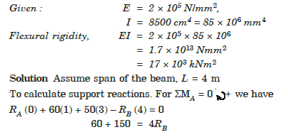
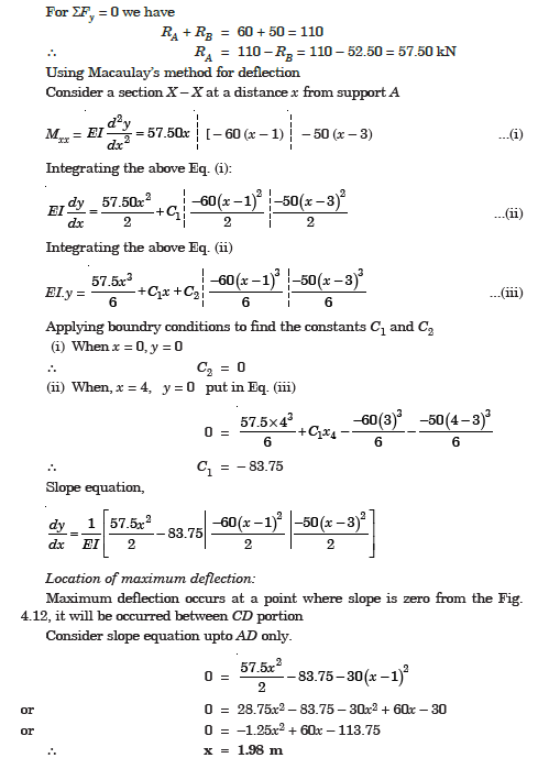
Q5) A beam, simply supported at ends A and B is located with two point loads of 60 kN and 50 kN at distance 1 metre and 3 metre respectively from end A. Determine the position and magnitude of maximum deflection. Take E = 2 × 10⁵ N/mm2 and I = 8500 cm4.
A4)

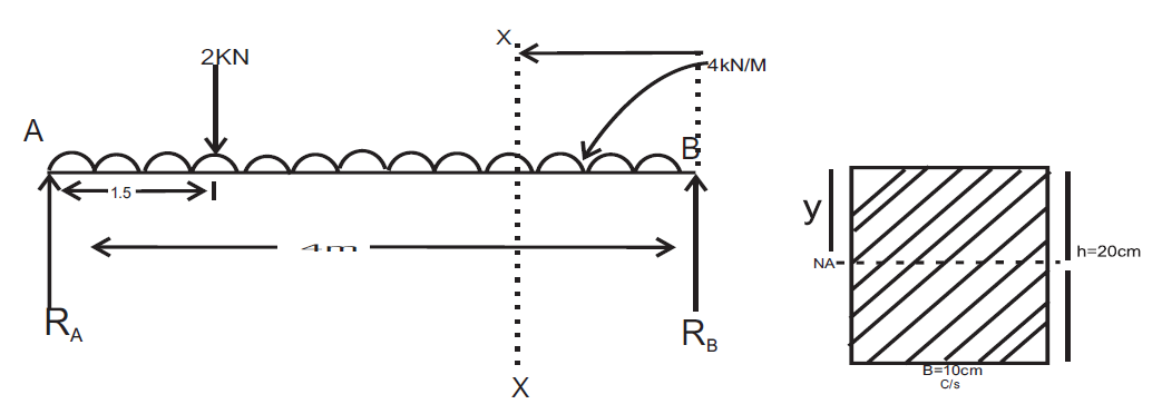
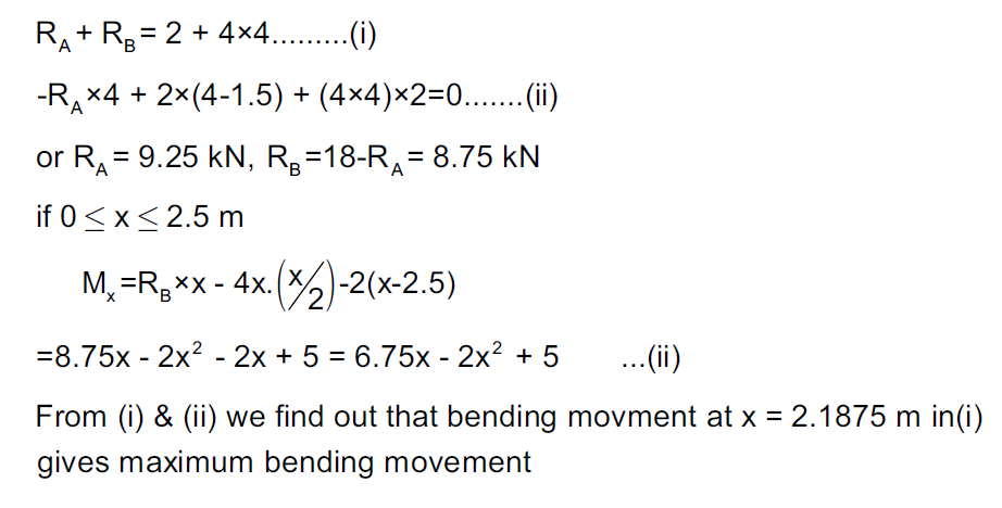
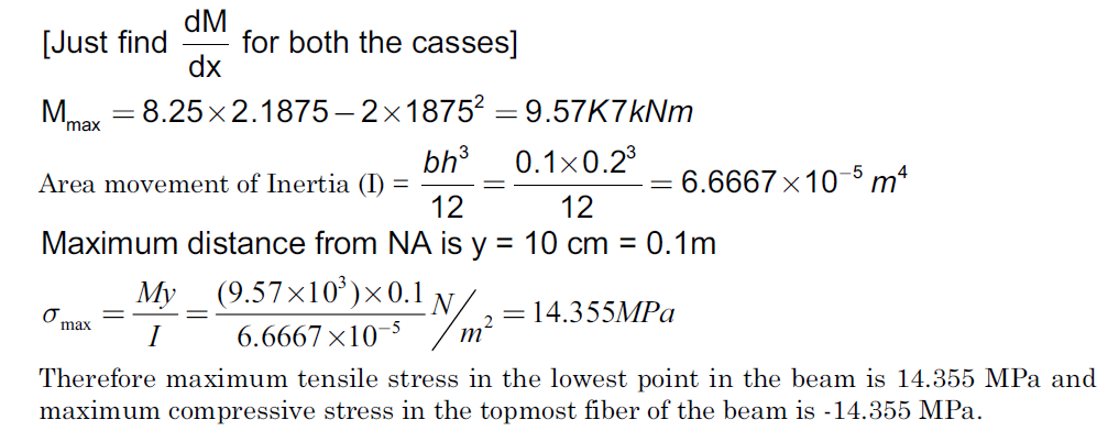
Q6) A Simply supported beam AB of span length 4 m supports a uniformly distributed load of intensity q = 4 kN/m spread over the entire span and a concentrated load P = 2 kN placed at a distance of 1.5 m from left end A. The beam is constructed of a rectangular cross-section with width b = 10 cm and depth d = 20 cm. Determine the maximum tensile and compressive stresses developed in the beam to bending.
A5)
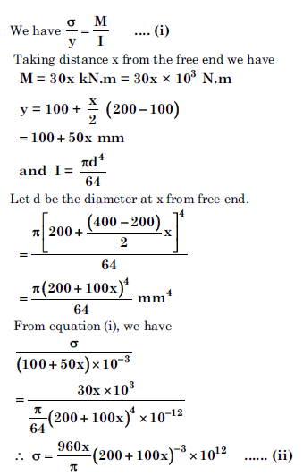
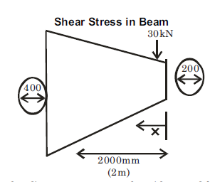
Q7) A cantilever of circular solid cross-section is fixed at one end and carries a concentrated load P at the free end. The diameter at the free end is 200 mm and increases uniformly to 400 mm at the fixed end over a length of 2 m. At what distance from the free end will the bending stresses in the cantilever be maximum? Also calculate the value of the maximum bending stress if the concentrated load P = 30 kN.
A6)


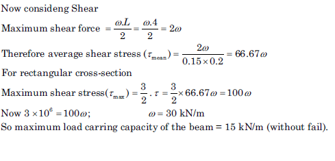
Q8) A timber beam 15 cm wide and 20 cm deep carries uniformly distributed load over a span of 4 m and is simply supported. If the permissible stresses are 30 N/mm2 longitudinally and 3 N/mm2 transverse shear, calculate the maximum load which can be carried by the timber beam.

A7)

