PRINCIPAL STRESSES, THEORIES OF FAILURE
Q1) Explain using analytical method principal stress for simple tensile stress in one direction.
A1) Assume a rectangular body with uniform cross-sectional area of unit thickness subjected to direct tensile stress in X-X axis. Now, consider an oblique section AB inclined with the axis X-X.
Let, σ = tensile stress across the face AC,
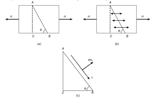
θ= angle, which AB makes with BC i.e. with the X-X axis
We know that horizontal force acting on the face AC is 
Resolving the force perpendicular to the section AB,
 ...(i)
Now resolving the force tangential to section AB
 ...(ii)
We know that normal stress across the section AB,
 …(iii)
 =
= 
Shear stress acting, 
Resultant stress is given by,

this gives the analytical way to solve one directional simple stresses for principal stress.
Q2) At a point in a material there are normal stresses of 30nN/mm2 and 60 N/mm2 tensile, together with a shearing stress of 22.5 N/mm2. Find the value of principal stresses and the inclination of the principal planes to the direction of the 60 N/mm2 stress.
A2) Given: σx = 30 N/mm2, σy = 60 N/mm2 τ = 22.5 N/mm2
Solution
To Find: σn1 ,σn2,θp1 ,θp2
Principal stress,


= 40 ± 27.04
Major principal stress σn1 = 45 + 27.04 = 72.04 N/mm2
Minor principal stress σn2 = 45 – 27.04 = 17.96 N/mm2
Position of principal plane,


= -1.5
tan (180 – 2θ) = –tan 2θ = 1.5
180 – 2θ = 56.3
2θ = 123.69
Θp1 = 61.8°
Θp2 = 90 + θp1 = 90 + 61.8° = 151.8
Q3) A point in a strained material is subjected to two mutually perpendicular tensile stresses of 200 MPa and 100 MPa. Determine intensities of normal shear and resultant stresses on a plane inclined at 30° with the axis of minor tensile stress.
A3) Normal stress on the inclined plane,


= 150 – 50 × 0.5 = 125 MPa
Shear stress on the inclined plane,

= 
=50 sin60
τ = 43.3 MPa
Resultant stress on the inclined plane,

= 
= 132.3 MPa
Q4) The stresses at a point of a machine component are 150 MPa and 50 MPa both tensile. Find the intensities of normal, shear, and resultant stresses on a plane inclined at an angle of 55° with the axis of major tensile stress. Also find the magnitude of the maximum shear stresses in the component.
Given: σx = 150 MPa, σy = 50 MPa, θ = 55°
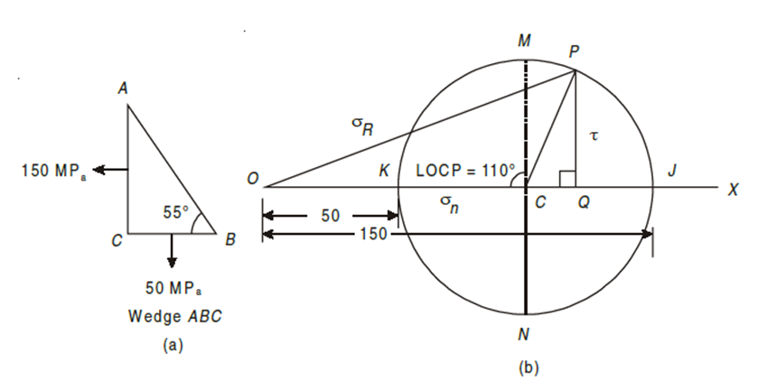
A4)
Q5) Direct stress of 120 MN/m2 in tension and 90 MN/m2 in compression are applied to an elastic material at a certain point on a plane at 25° with the tensile stress. If the maximum principal stress is not to exceed 150 MN/m2 in tension to what shearing stress can the material be subjected? What is then the maximum resulting shearing stress in the material and also find the magnitude of the other principal stress and its inclination to plane of 120 MN/m2 stress.
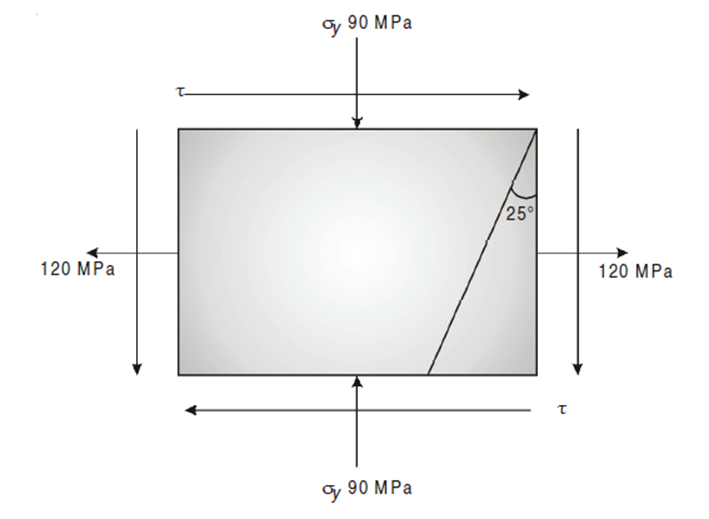
Given :
σn1 = 150 MPa, σx = 120 MPa, σ = –90 MPa
Major principal stress is given by,


(150 – 15)2 = 1052 + τ2
τ = 84.85 N/mm2
Minor principal stress,


= -120N/mm2
Maximum shear stress,


 N/mm2
N/mm2
Position of principal plane,


 0.808
0.808
θp1 = 19.47 or 90 + 19.47 = 109.47
Position of maximum shear stress,
θs1 = θp1+ 45°
= 19.47° + 45° = 64.47°
θs2 = θp2+ 45° = 154.47°
Q6)Construct Mohr’s circle for the case of plane stress σx = 360 kg/cm2, σy = 200 kg/cm2 and τxy = 60 kg/cm2 and determine the magnitudes of the two principal stresses σ1 and σ2 and the angle φ between the direction σx and σ1.
A6) Given: σx = 360 kg/cm2, σy = 200 kg/cm2, τxy = 60 kg/cm2
To Find: σ1, σ2, φ
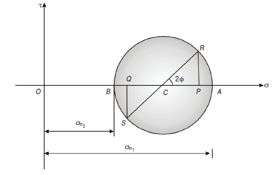
σn1 = OA × scale = 7.6 × 50 = 380 kg/cm2
σn1= OB × scale = 3.5 × 50 = 175 kg/cm2
Angle φ between the direction σx and σ1
∠PCR = 2φ = 35
φ = 35/2 = 17.5°
Q7) An element in a strained body is subjected to a tensile stress of 150 MPa and a shear stress of 50 MPa tending to rotate the element in an anticlockwise direction. Find (i) the magnitude of the normal and shear stresses on a section inclined at 40° with the tensile stress; and (ii) the magnitude and direction of maximum shear stress that can exist on the element.
A7) Given: Tensile stress along horizontal X – X axis (σx) = 150 MPa; shear stress (τxy) = – 50 MPa (Minus sign due to anticlockwise) and angle made by section with the tensile stress (θ) = 40°.
The given stresses on the plane AB of the element and a shear stress on the plane BC are shown in Fig. (a). Now
draw the Mohr’s Circle of Stresses as shown in Fig.(b) and as described below:
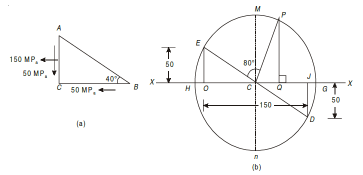
1. First of all take some suitable point O, and through it draw a horizontal line XOX.
2. Cut off OJ equal to the tensile stress on the plane AC (i.e. 150 MPa) to some suitable scale towards right.
3. Now erect a perpendicular at J below the line X – X and cut off JD equal
to the negative shear stress on the plane AC (i.e. 50 MPa) to the scale. The point D represents the stress system on the plane AC. Similarly erect a perpendicular at O above the line X – X and cut off OE equal to the negative shear stress on the plane BC (i.e. 50 MPa) to the scale. The point E represents the stress systems on the plane BC. Join DE and bisect it at C.
4. Now with C as centre and radius equal to CD or CE draw the Mohr’s
Circle of stresses meeting the line X – X at G and H.
5. Through C, draw two lines CM and CN at right angles to the line X – X
meeting the circle at M and N. Also through C, draw a line CP making an angle
of 2 × 40° = 80° with CE in clockwise direction meeting the circle at P. The point P represents the stress system on the section AB.
By measurement, we find that the Normal stress (σn) = OQ = 112.2 MPa; Shear stress (τ) = QP = 82.5 MPa and maximum shear stress, that can exist on element (τmax) = ± CM = CN = 90.14 MPa.
Q8) The stresses at a point of a machine component are 150 MPa and 50 MPa both tensile. Find the intensities of normal, shear, and resultant stresses on a plane inclined at an angle of 55° with the axis of major tensile stress. Also find the magnitude of the maximum shear stresses in the component.
A8) Given: σx = 150 MPa, σy = 50 MPa, θ = 55°
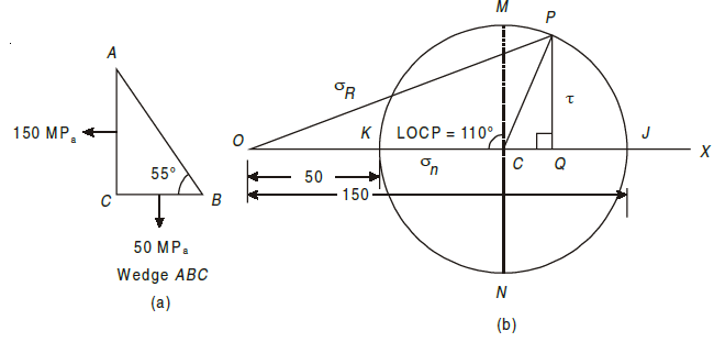
The given stresses on the planes AC and BC in the machine component are shown in Fig. (a). Now draw the Mohr’s circle of stresses as shown in Fig. (b).
2. Cut off OJ and OK equal to the tensile stresses σx and σy respectively i.e., 150 MPa and 50 MPa to some suitable scale towards right. The point J represents the stress system on plane AC and the point K represents the stress system on plane BC. Bisect KJ at C.
3. Now with C as centre and radius equal to CJ or CK draw the Mohr’s circle of stresses.
4. Now through C draw two lines CM and CN at right angles to the line OX meeting the circle at M and N. Also through C draw a line CP making an angle of 2 × 55° = 110° with CK in clockwise direction meeting the circle at P. The point P represents the stress systems on the plane AB.
5. Through P, draw PQ perpendicular to the line OX. Join PO. By measurement we find, normal stress (σn) = OQ = 117.1 MPa,
shear stress (τ) = QP = 47.0 MPa,
resultant stress (σR) = OP = 126.17 MPa and
maximum shear stress (τmax) = CM = ± 50 MPa.
Q9) The stresses at a point in a component are 100 MPa (tensile) and 50 MPa (Comp.) Determine the magnitude of the normal and shear stresses on plane inclined at an angle of 25° with tensile stress. Also determine the direction of the resultant stress and the magnitude of the maximum intensity of shear stress.
A9) σx = 100 MPa
σy = –50 MPa
θ = 25°
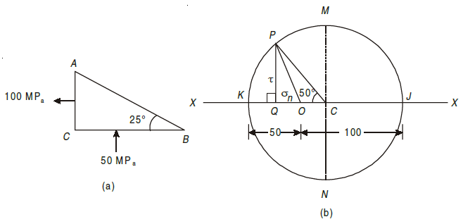
The given stresses on planes AC and BC are shown in Fig. (a)
Now draw Mohr’s circle of stresses (Fig. (b)) discussed below.
1. Take some suitable point O and through it draw a horizontal line XOX.
2. Cut off OJ and OK equal to the stresses σx and σy (100 MPa and –50 MPa) to some suitable scale. Bisect KJ at C.
3. Now with C as centre and radius equal to CJ or CK draw Mohr’s circle of stresses.
4. Now through C, draw two lines CM and CN at right angles to the line OX meeting the circle at M and N. Also, through C, draw a line CP making an angle of 2 × 25 = 50° with CK in clockwise direction meeting the circle at P. The point P represents the stress system on the plane AB.
5. Through P, draw PQ perpendicular to the line OX. Join OP.
By measurement, we find that the normal stress σn = OQ = –23.21 MPa,
shear stress (τ) = PQ = 57.45 MPa.
Direction of the resultant stress ∠ POQ = 68.1° and maximum shear stress
(τmax) = ± CM = CN = ± 75 MPa.
Q10) A plane element in a body is subjected to a tensile stress of 100 MPa accompanied by a clockwise shear stress of 25 MPa. Find (i) The normal and shear stress on a plane inclined at an angle of 20° with the tensile stress; and (ii) the maximum shear stress on the plane.
A10) Given
Tensile stress along horizontal X– X axis (σx) = 100 MPa, shear stress
(τxy) = 25 MPa and angle made by plane with tensile stress (θ) = 20°.
The given stresses on the element and a complimentary shear stress on the BC plane are shown in Fig. (a).
Now draw the Mohr’s circle of stresses as shown in Fig.(b) and as
described below:
1. First of all, take some suitable point O, and through it draw a horizontal line XOX.
2. Cut off OJ equal to tensile stress on the plane AC (i.e., 100 MPa) to some
suitable scale towards right.
3. Now erect a perpendicular at J above the line X – X and cut off JD equal
to the positive shear stress on plane BC (i.e., 25 MPa) to the scale. The point D represents the stress system on the plane AC. Similarly erect a perpendicular at O below the line X – X and cut off OE equal to the negative shear stress on the plane BC (i.e., 25 MPa) to the scale. The point E represents the stress system on the plane BC. Join DE and bisect at C.
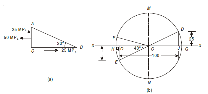
4. Now with C as centre and radius equal to CD or CE draw a Mohr’s circle of stresses.
5. Now through C, draw two lines CM and CN at right angle to the line OX meeting the circle at M and N. Also, through C, draw a line CP making An angle of 2 × 20° = 40° with CE in clockwise direction meeting the circle a P. The point P represents the stress system on section AB.
6. Through P, draw PQ perpendicular to the line OX. Join QP.
By measurement: (i) Normal stress (σn) = OQ = 4.4 MPa (Comp.), (ii) Shear
stress τ = QP = 13.0 MPa, and (iii) Maximum shear (τmax) = CM = 55.9 MPa
Q11) Explain all the theories of failure.
A11) VARIOUS THEORIES OF FAILURE
Maximum Principal Stress Theory
According to this theory maximum principal stress induced in material under complex load condition exceeds the maximum normal strain in simple test, the material fails.
Failure condition, 
 = yield point stress

This theory is not suitable to design machine elements as  and
and  are in opposite direction.
Maximum Shear Stress Theory
According to this theory when maximum shear strength in actual case exceeds maximum allowable shear stress in tension test then material fails.


This theory is widely used in the analytical way to calculate for the ductile materials. This has proved to be widely used theory for simple calculations in designing of simple machine elements.
Maximum Principal Strain Theory
It states that when normal strain in actual case is more than maximum normal strain, strain occurred in simple tension test, material fails. This theory deals with the strain energy in the distorted material.

Maximum Strain Energy Theory
The energy stored in the material when the material is said to be deformed is called as strain energy. According to this theory when total strain energy exceeds the total strain energy in simple tensile test then material fails.
The condition is given by,

This condition gives the limiting condition of the strain energy in the material or else the material will fail.
Distortion Energy Theory
The distortion energy is also known as deviatoric energy it is the shear stress energy in the material. When maximum shear strain energy in actual case is more than maximum shear strain in simple tension test, material fails. This theory is highly recommended but used rarely due to difficult calculations.
The condition for limiting value is,

This is the maximum distortion energy in the material after this limit the material fails.