Unit 6
Application Based Combined loading and stresses
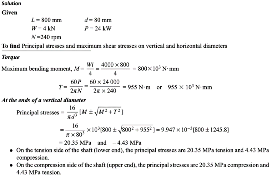
Q1) A 800 mm long shaft with a diameter of 80 mm carries a flywheel weighing 4 kN at its midway. The shaft transmits 24 kW at a speed of 240 rpm. Determine the principal stresses and the maximum shear stress at the ends of a vertical and horizontal diameter in a plane near the flywheel.
A1)

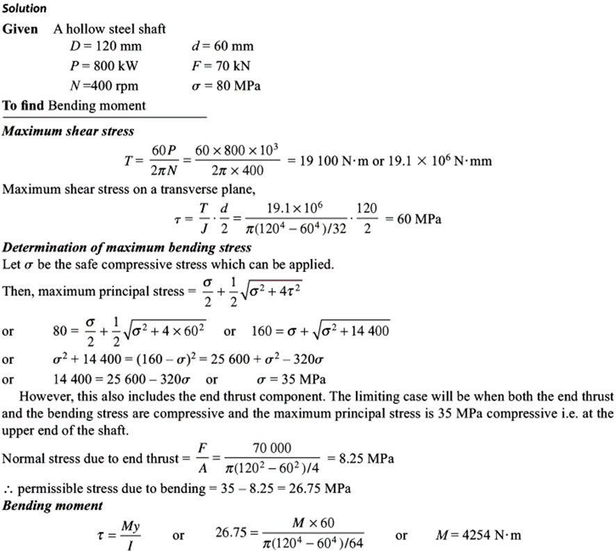
Q2) The outer and inner diameter of hollow steel shaft are 120 mm and 600 mm respectively. The shaft transmits 800 kW at a speed of 400 rpm while at end thrust of 70 kN acts on the shaft. Determine the bending moment which can safely be applied to the shaft if the maximum principal stress do not exceed 80 Mpa.
A2)
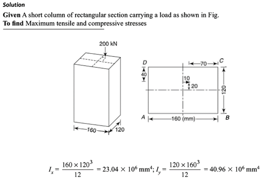
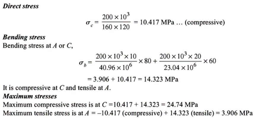
Q3) A short column of rectangular section 160 mm x 120 mm carries a load of 200 kN. The load point is at a point 40 mm from the longer side and 70 mm from the shorter side. Determine the maximum tensile and compressive stresses in the section.
A3)
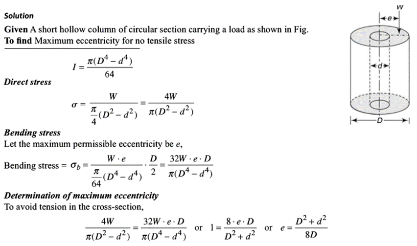
Q4) A short column of external and internal diameters as D and d respectively carries an eccentric load W. Determine the maximum eccentricity which the load can have without producing the tension on the cross-section of the column.
A4)
Q5) A point in a strained material is subjected to a tensile stress of 65 N/mm2 and a compressive stress of 45 N/mm2, acting on two mutually perpendicular planes and a shear stress of 10 N/mm2 are acting on these planes. Find the normal stress, tangential stress and resultant stress on a plane inclined to 30° with the plane of the compressive stress
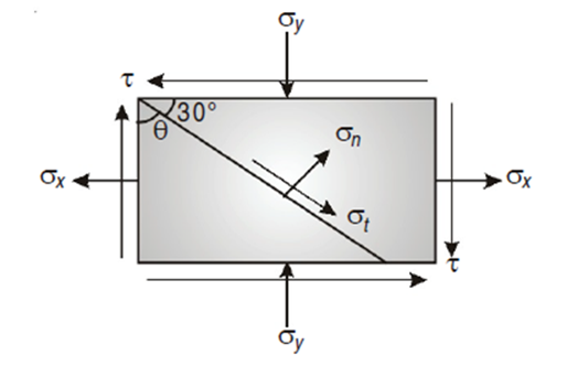
A5) Given:
Here
σx = 65 N/mm2
σy = –45 N/mm2 (Compressive ∴ – ve)
θ = (90 – 30) = 60° with the plain of σx.
τ = 10 N/mm2
To find: σn, σt, σR.
Analytical solution,
 +
+
= 
= 52.63 N/mm2
Tangential stress,
 -
- 
=  -10.
-10.
= 52.63 N/mm2
Resultant stress  t
t
= 53.36 N/mm2
Angle of obliquity φ =  = 80.46 degree
Q6) Direct stress of 120 MN/m2 in tension and 90 MN/m2 in compression are applied to an elastic material at a certain point on a plane at 25° with the tensile stress. If the maximum principal stress is not to exceed 150 MN/m2 in tension to what shearing stress can the material be subjected? What is then the maximum resulting shearing stress in the material and also find the magnitude of the other principal stress and its inclination to plane of 120 MN/m2 stress.
A6)
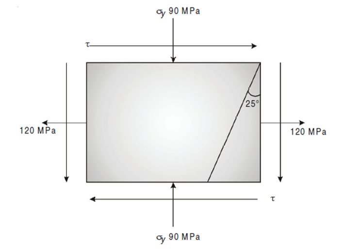
Given :
σn1 = 150 MPa, σx = 120 MPa, σ = –90 MPa
Major principal stress is given by,


(150 – 15)2 = 1052 + τ2
τ = 84.85 N/mm2
Minor principal stress,


= -120N/mm2
Maximum shear stress,


 N/mm2
N/mm2
Position of principal plane,


 0.808
0.808
θp1 = 19.47 or 90 + 19.47 = 109.47
Position of maximum shear stress,
θs1 = θp1+ 45°
= 19.47° + 45° = 64.47°
θs2 = θp2+ 45° = 154.47°
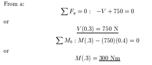
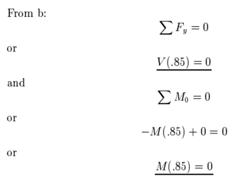
Q7) A bar is fixed at one end and is loaded as illustrated. Ignoring the weight of the bar, compute the internal reaction force and moment at points A and B.

A7)

Fig a
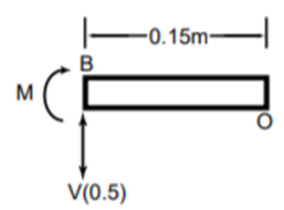
Fig b
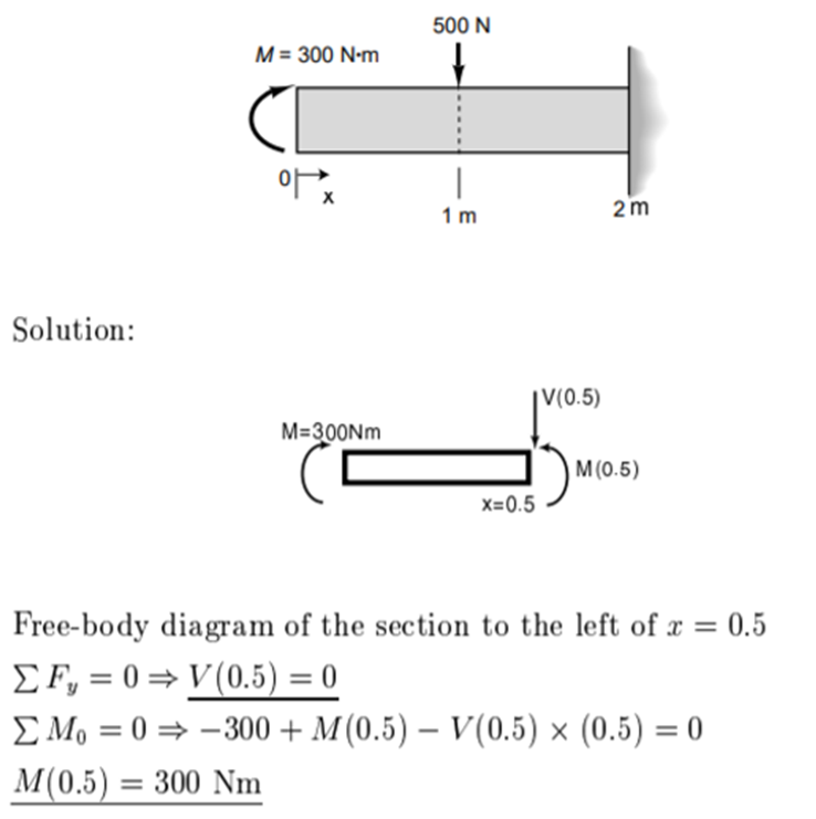
Q8) Compute the internal reaction force and moment at 0.5 mm from the left end for the system given below
Q9) Explain the procedure to solve the problems of combined stresses.
A9) The procedure to solve problems of combined stresses includes the following steps:

Q10) Give the procedure to determine the internal forces and moments.
A10) The procedure to calculate internal forces is as follows:
To find the reactions at external supports, condition of equilibrium is used. These conditions of equilibrium are:

b. Algebric sum of the forces in Y direction is equal to zero

c. Algebric sum of the moments at a particular point due to all forces is equal to zero.

iii. Find reactions at connections.
iv. Keep all loads in their exact locations.
v. Pass a section cut through the member perpendicular to its axis at the point where the internal loads are to be determined,
vi. Draw FBD of cut member.
vii. For 2D problem find N, V, M (normal force, shear force and moment respectively) from equilibrium.